Table of Contents
Advertisement
Quick Links
Installation, Operation, and
Maintenance
®
Tracer
UC600 Programmable Controller
Ordering Number: BMUC600AAA0100011
Only qualified personnel should install and service the equipment. The installation, starting up, and servicing
of heating, ventilating, and air-conditioning equipment can be hazardous and requires specific knowledge and
training. Improperly installed, adjusted or altered equipment by an unqualified person could result in death or
serious injury. When working on the equipment, observe all precautions in the literature and on the tags,
stickers, and labels that are attached to the equipment.
SAFETY WARNING
BAS-SVX45F-GB
Advertisement
Table of Contents
Troubleshooting

Related Manuals for Trane Tracer UC600


Summary of Contents for Trane Tracer UC600
- Page 1 Installation, Operation, and Maintenance ® Tracer UC600 Programmable Controller Ordering Number: BMUC600AAA0100011 SAFETY WARNING Only qualified personnel should install and service the equipment. The installation, starting up, and servicing of heating, ventilating, and air-conditioning equipment can be hazardous and requires specific knowledge and training.
- Page 2 DISCONNECTING, OR VOLTAGE TESTING WITHOUT PROPER ELECTRICAL PPE AND ARC FLASH CLOTHING. ENSURE ELECTRICAL METERS AND EQUIPMENT ARE PROPERLY RATED FOR INTENDED VOLTAGE. Failure to follow instructions could result in death or serious injury. © 2016 Trane All rights reserved BAS-SVX45F-GB...
- Page 3 Introduction Copyright This document and the information in it are the property of Trane, and may not be used or reproduced in whole or in part without written permission. Trane reserves the right to revise this publication at any time, and to make changes to its content without obligation to notify any person of such revision or change.
-
Page 4: Table Of Contents
Device ID Assignment for Wireless Devices ..... . . 17 Rotary Dial Address Settings for Non-Trane Systems ....17 Tracer UC600 Pre-power Checks . - Page 5 Configuring Tracer UC600 ........
- Page 6 Disable HTTP Communications ....... . . 82 Disable Tracer UC600 User Interface (TD7) ......82 Declaration of CE Conformity .
-
Page 7: Overview
The Air-Fi™ Wireless Communications Interface (WCI) is an alternative to BACnet® wired communication links. The WCI is a wireless communications component (option) added to Tracer controllers and is compatible with Tracer UC600. Tracer UC600 firmware must be at V4.00.027 or higher for compatibility with WCI. -
Page 8: Specifications
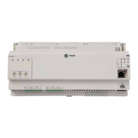
UL 840: Degree 2 Location of LEDs Light emitting diodes (LEDs) indicate the operation and communication status of the controller. To interpret the Tracer UC600 LEDs and safely operate the Tracer UC600, see “LED Descriptions and Activities, ” p. For detailed information about wiring communication links, refer to Tracer SC Unit Controller Wiring Guide (BAS-SVN03) listed in the section, “Other Resources, ”... -
Page 9: Hardware Terminations
Overview Hardware Terminations Tracer UC600 supports the following hardware terminations: • Temperature sensors (resistive and thermistor) • Linear inputs 0–20 mA, such as humidity sensors • Linear inputs 0–10 VDC, such as indoor air-quality sensors • Linear outputs 0-20 mA, such as variable frequency drives •... -
Page 10: Agency Listings And Compliance
Overview Agency Listings and Compliance This section lists compliance with Conformity European (CE) and Underwriters Laboratories (UL) standards for the UC600 controller: • UL916 PAZX, Open Energy Management Equipment • UL94-5V, Flammability • CE Marked • FCC Part 15, Subpart B, Class B Limit •... -
Page 11: Dimensions And Clearances
Overview Dimensions and Clearances Figure 2. Controller dimensions 215.9 mm width (12 DIN units)* IM C IM C + 24 + 24 + 24 XFMR MBUS LINK UI 1 UI 2 UI 3 UI 4 UI 5 UI 6 UI 7 UI 8 U C 600 LINK... - Page 12 Overview Figure 3. DIN rail clearances 101.6 mm Controller Height 50.8 mm 180 mm Wiring Space Between Controllers (see note) Centerline to Centerline Note: Allow a minimum of 50.8 mm wiring space between controllers, sides of controllers, and bottom of cabinet. Represents Terminal Connector BAS-SVX45F-GB...
-
Page 13: Installation
Installation This section describes how to install Tracer UC600 onto a DIN rail and set rotary switches. Mounting and Removing the Tracer UC600 Controller The Tracer UC600 controller should be properly mounted on a DIN rail. To mount or remove the controller from the DIN rail, follow the illustrated instructions in Figure 4 Figure 5, p. - Page 14 Installation Figure 5. Removing the Tracer UC600 To remove or reposition the controller: 1. Disconnect all connectors before removing or repositioning. 2. Insert screwdriver into slotted release clip and gently pry upward with the screwdriver to disengage the clip. 3. While holding tension on the clip, lift device upward to remove or to reposition.
-
Page 15: Setting Addresses Using Rotary Switches
Installation Setting Addresses using Rotary Switches There are three rotary switches on the front of the Tracer UC600 for the purpose of defining a three- digit address when it is installed on a BACnet communications network. The three-digit address setting is used as both the rotary switch value and the BACnet device ID. -
Page 16: Setting The Bacnet Device Id
UC600 rotary switch value. For example, the Tracer SC will create a BACnet device ID of 101030 under the following conditions: – The rotary dials on Tracer UC600 are set to 30 (0,3,0), which is also known as the rotary switch address. -
Page 17: Device Id Assignment For Bacnet/Ip Devices
MSTP link. For non-Trane systems, the Max Master value must be greater than the unique address settings from the rotary dials. Although 999 is possible from the dials, the maximum allowed number by BACnet is 127. -
Page 18: Tracer Uc600 Pre-Power Checks
Analog outputs; verify that AC voltage is not present and that the load does not have 24 VAC or 230 VAC. This section provides illustrations and methods of how to check the Tracer UC600 points before connection has been made and power applied. The step numbers in each illustration correspond to the information in each table. -
Page 19: Voltage Inputs
Tracer UC600 Pre-power Checks Voltage Inputs The sensor sources voltage and is powered. Checkout Procedure Measurement Expected Value VAC ≈ 0.0 V Step 1 Measure AC voltage across the voltage input. AC voltage will affect further measurement. Compare the measured voltage with the Step 2 Measure DC voltage across the voltage termination. -
Page 20: Binary Inputs
Tracer UC600 Pre-power Checks Binary Inputs Checkout Procedure Measurement Expected Value VAC ≈ 0.0 V Step 1 Measure AC voltage across the resistive termination. AC voltage will affect further measurement. VDC ≈ 0.0 V Step 2 Measure DC voltage across the resistive termination. -
Page 21: Power Budget Check In An Un-Powered State
This section provides information about power budget consumption for the UC600 in an un-powered state. Calculating AC Power Consumption Tracer UC600, along with the 24 VAC transformer, can draw up to 26 VA AC power. Observe the following rules when calculating AC power: •... -
Page 22: Calculating Dc Power Consumption
Power Budget Check in an Un-powered State Calculating DC Power Consumption The UC600 is capable of providing 600 mA of power. Observe the following rules when budgeting for DC power: • The UC600 can power a maximum of two small modules (WCIs, expansion modules) and a maximum of 10 points configured as 4-20 mA In/Out (loop powered), simultaneously. -
Page 23: Wiring And Powering The Tracer Uc600
Wiring and Circuit Requirements All wiring must comply with the National Electrical Code and local electrical codes. To ensure proper operation of the Tracer UC600, observe the following guidelines: • The controller should receive AC power from a dedicated power circuit; failure to comply may cause the controller to malfunction. -
Page 24: Transformer Requirements
Wiring and Powering the Tracer UC600 Transformer Requirements • AC transformer requirements: UL listed, Class 2 power transformer, 24 VAC ±15%, device max load 26 VA. The transformer must be sized to provide adequate power to the UC600 controller (26 VA) and any external device outputs. -
Page 25: Wiring Ac Power To Tracer Uc600
Wiring and Powering the Tracer UC600 Wiring AC Power to Tracer UC600 1. Connect both secondary wires from the 24 Vac transformer to the XFMR terminals on the device. 2. Ensure the device is properly grounded. Important: This device must be grounded for proper operation! The factory-supplied... -
Page 26: Controller Startup And Power Check
4. Using a digital multimeter (DMM), verify that 24 VAC is present at the 24 VAC connector. If voltage reading is within plus or minus 10%, connect the 24 VAC connector to the transformer XMRF input on the UC600. The following table describes the Tracer UC600 service and power LED indicators. Table 8. LED startup sequence Power LED Indicates... -
Page 27: Bacnet Ms/Tp Link Wiring
“Other Resources, ” p. The illustration below shows an example of BACnet link wiring with a combination of Tracer UC600 and Tracer UC400 controllers. Note: A maximum of 20 UC600 controllers are allowed per Tracer SC (10 per MSTP link). -
Page 28: Wiring Inputs And Outputs
Thermistor input and 0–10 VDC input or output wiring must not exceed 100 m. Avoid Equipment Damage! Remove power to the Tracer UC600 controller before making input or output connections. Failure to do so may cause damage to the controller, power transformer, or input/output devices due to inadvertent connections to power circuits. -
Page 29: Providing Low-Voltage Power For Inputs/Outputs
Wiring Inputs and Outputs Providing Low-voltage Power for Inputs/Outputs Tracer UC600 is capable of providing low-voltage power to the inputs/outputs. For limitations, refer to the section, “Calculating AC Power Consumption, ” p. Note: More than one input or output can receive power from a given terminal. However, the only limitation is the total amount of supplied power. -
Page 30: Wiring Universal Inputs
Wiring Inputs and Outputs Wiring Universal Inputs e UC600 has a total of 14 universal input and output terminals: eight universal inputs located on the upper tier and six universal input/output terminals on the bottom tier. Refer to Table 2, p. 9 for device connections and ranges. -
Page 31: Wiring 0-10 Vdc Analog Inputs
Wiring Inputs and Outputs Wiring 0–10 VDC Analog Inputs Connect 0–10 VDC analog inputs to sensors such as indoor air quality sensors and pressure sensors. Wiring can be done on the top tier or the bottom tier by using a combination of universal and analog input terminations. -
Page 32: Wiring 0-20 Ma Analog Inputs
Wiring Inputs and Outputs Wiring 0–20 mA Analog Inputs Connect any 0–20 mA analog input to sensors such as humidity sensors and pressure sensors. 1. Connect the shield to a common terminal at the terminal board and tape it back at the input device. -
Page 33: Wiring Variable Resistance Analog Inputs
Wiring Inputs and Outputs Wiring Variable Resistance Analog Inputs Variable resistance analog inputs include 10K thermistors, resistance temperature detectors (RTD), and setpoint thumbwheels on zone sensors. To wire a variable resistance analog input: 1. Connect the shield to a common terminal at the terminal board and tape it back at the input device. -
Page 34: Wiring Trane Zone Sensors
Wiring Trane Zone Sensors The table in Figure 14 shows the terminations on a Trane zone sensor and a typical UC600 application. 1. Connect the shield to a common terminal at the terminal board device. Note: Do Not use the shield as the common connection. For 3-wire applications, use a 3-conductor cable with shield and for 2-wire applications, use a 2-conductor cable with separate shield. -
Page 35: Wiring Analog Outputs
Wiring Inputs and Outputs Wiring Analog Outputs The UC600 has six analog output terminations. These outputs can be used for 0–10 VDC outputs or 0–20 mA outputs and used to control actuators or secondary controllers. To wire an analog output: 1. -
Page 36: Wiring Binary Outputs
Wiring Inputs and Outputs Wiring Binary Outputs The UC600 has four binary outputs that are used as powered outputs. Notice: Controlling coil-based loads: Inrush current (the initial surge of a current into a load before it attains normal operating condition) can be three times greater, or more, than the operating current. Important: Use pilot relays for dry contact outputs for load currents greater than 0.5 amperes and use powered outputs for load currents less than 0.5 amperes. -
Page 37: Connecting Pressure Transducer Inputs
Connecting Pressure Transducer Inputs Tracer UC600 is equipped with one 3-pin, 5 VDC pressure transducer input connection (P1) designed for Kavlico pressure transducers. Transducers measure duct static pressure in the Tracer UC600 equipment (VAV AHUs) that is detected from the connected sensor (mounted near the Tracer UC600). -
Page 38: Tracer Uc600 Operation
Tracer UC600 Operation LED Descriptions and Activities The following table provides a description of LED activity, indicators, and troubleshooting tips. Refer to Figure 1, p. 8, for locations of the LEDs. Table 11. LED identification and interpretation LED type LED activity Indicates... -
Page 39: Troubleshooting
Tracer SC. Possible solution: Reinstall the Tracer UC600 device onto the Tracer SC. 1. Verify that the Tracer UC600 device ID is set to the rotary address, which is found in TracerTU/ controller/controller settings/protocol. 2. Log on to Tracer SC and navigate to the Devices page; select the Tracer UC600 device from the list, then select replace from the actions button. -
Page 40: Connection Problems
Tracer UC600 Operation Connection Problems Problem: Tracer UC600 is not responding, communicating, or is unable to connect with Tracer SC or the Tracer TU service tool. (For more information about the Tracer TU service tool, see “Configuring Tracer UC600 with Tracer TU, ” p. -
Page 41: Configuring Tracer Uc600 With Tracer Tu
When connecting to the controller for the first time, the Found New Hardware Wizard appears. Figure 17. Found New Hardware Wizard screen 2. If the Tracer UC600 appears, select Install the software automatically (Recommended) and then click Next. If the Tracer UC600 does not appear, repeat the Tracer TU installation. -
Page 42: Connecting Using Tracer Sc
Startup Task Panel dialog box. To add a facility, you must know the IP address assigned to the Tracer SC. The Tracer UC600 must also be installed onto the Tracer SC in order for the Tracer SC to pass through by way of an IP address. - Page 43 (Figure 21, p. 44). 8. From the left navigation menu, click on the Tracer UC600 to which you want to connect. Note: Tracer UC600 must be installed in the Tracer SC in order to access the device through the SC. BAS-SVX45F-GB...
-
Page 44: Tracer Tu Installation And Connection Error Conditions
Figure 21. Unit summary screen Tracer TU Installation and Connection Error Conditions During installation or initial connection to a Tracer UC600, the user may encounter an error message or error condition. The messages with corrective actions are listed in the following table. -
Page 45: Upgrading Firmware
Firmware upgrades require the use of Tracer TU (version 8.0 or higher). To upgrade Tracer UC600 firmware: 1. Connect Tracer TU to Tracer UC600 using a USB connection (direct connect). It is not recommended that the firmware be updated using single-link access or connecting through the Tracer SC. -
Page 46: Configuring Tracer Uc600 And Creating Or Editing Points
3. Click Controller Units and set the preferred units of measure and then click Send to Device. 4. Click Protocol to display a list of protocols that the Tracer UC600 uses to communicate with other controllers. For BACnet protocol, specify the Baud Rate, and then click Send to Device. -
Page 47: Using Pre-Packaged Solutions (Pps)
Home.aspx, or enter pre-packaged solutions in the search field. 2. Locate the Tracer UC600 PPS file, then select to save the file to your hard drive. 3. Open a session of Tracer TU. 4. Click on the File Transfer Utility icon located in the upper left-hand side of the TU window and then click Next. - Page 48 Configuring Tracer UC600 with Tracer TU Figure 24. Creating a new point 6. Click Save to File to save the new point configuration or click Send to Device to send the new point configuration to the controller. To edit, copy, or delete a point: 1.
-
Page 49: Placing Points In Out-Of-Service Mode
Tracer TU will automatically define the number of states and the state text, based on the selected property. Note: Tracer TU Version 8.1 and Tracer UC600 Version 3.34 and higher are required for this functionality. -
Page 50: Creating Points For Timed Override (Tov) And */** Functions
Configuring Tracer UC600 with Tracer TU Figure 25. Creating multistate points to monitor communication status Select an XM module from the Device node Creating Points for Timed Override (TOV) and */** Functions Functionality for TOV and */** (thumb wheel) functions can be configured for the UC600, UC400, and the XM70. - Page 51 Configuring Tracer UC600 with Tracer TU Figure 26. TOV point configuration Select “analog value” from Select this the reference check box dialog box. To create points for the */** function 1. Complete steps 1 through 6 as described in “To create points for TOV functions, ” p.
- Page 52 Configuring Tracer UC600 with Tracer TU 1. Open up a session of TGP2. 2. Select the point type from the left side bar; click and drag onto the editing space. 3. Right-click and then choose Block Properties from the menu. The Point Properties Dialog box appears.
-
Page 53: Monitoring And Viewing The Status Of The Tracer Uc600
Configuring Tracer UC600 with Tracer TU Monitoring and Viewing the Status of the Tracer UC600 Use the Status Utility tab to monitor and view the details of Tracer UC600 points list, alarms, and controller status. To monitor and view details: 1. -
Page 54: Backup
7. Click Start. A dialog box containing a progress meter appears. When the transfer process is complete, a confirmation message appears. 8. Click Finish. Note: Backup files are controller dependent. Backup files made for a Tracer UC600 can only be restored on a Tracer UC600. BAS-SVX45F-GB... -
Page 55: Setting Up And Maintaining Schedules
Configuring Tracer UC600 with Tracer TU Setting Up and Maintaining Schedules Tracer UC600 supports three types of schedules: analog, binary, and multistate. Schedules can be set up and maintained in Tracer TU and the Tracer TD7 Display (see “Tracer TD7 Display, Installation, Operation, and Maintenance, “BAS-SVX50”). - Page 56 Configuring Tracer UC600 with Tracer TU 5. Enter a schedule Name and Description. The Type and Dimensionality boxes will be populated based on the selections you make in the Members group box. 6. Expand the Members group box and select the Point Type (Analog, Binary, or Multistate) from the Point Type drop-down list.
-
Page 57: Changing The Schedule Default Value And Adding Events
Configuring Tracer UC600 with Tracer TU Changing the Schedule Default Value and Adding Events After creating a schedule and selecting the members, the next step is to determine the schedule default value and add weekly events. An event is defined as a time-value pair. - Page 58 Configuring Tracer UC600 with Tracer TU Adding Events 1. From the Actions drop-down list, select Add Event then click Go to display the Events dialog (Figure 34). Events for a particular day can be viewed by selecting the day of the week at the top of the Add...
-
Page 59: Adding Exceptions To A Schedule
Configuring Tracer UC600 with Tracer TU 3. Repeat the above steps to add up to 10 events for each day of the week. Click OK to return to the Schedules page. To modify events on a particular day: Select a day in the Event Table from the Add Event dialog box. Use the arrow buttons to change the value. - Page 60 Configuring Tracer UC600 with Tracer TU To add exceptions: 1. Open the schedule to which you want to add exceptions. 2. From the Actions drop-down list Select Add Exceptions. Click Go to display the Add Exceptions dialog box (Figure 36). (Or access from the Exception list page).
- Page 61 Configuring Tracer UC600 with Tracer TU Click on day in the resultant to view all exceptions applied to the day from the highest priority to the lowest, with normal events at the bottom. Figure 37. Typical schedule (resultant) with events and exceptions...
-
Page 62: Modifying Exceptions
Configuring Tracer UC600 with Tracer TU Modifying Exceptions 1. Open the schedule containing the exception you want to modify. 2. Select an exception from those listed in the Exceptions group box. 3. From Actions drop-down list, select Modify Selected Exception, then click Go. -
Page 63: Deleting Exceptions
Configuring Tracer UC600 with Tracer TU 5. Repeat for all other affected days. 6. Click OK to return to the schedule. Deleting Exceptions 1. Open the schedule containing the exception you want to delete. 2. Select an exception from those listed in the Exceptions group box. - Page 64 Configuring Tracer UC600 with Tracer TU Figure 41. Accessing the TD7 operator display user interface Click to access the TD7 operator display Custom graphics are created and loaded using Tracer Graphics Editor (TGE). See the TGE online help for more information. Standard graphics are available in the most recent Pre-Packaged Solutions (PPS) library at https://home.ingerrand.com/our%20businesses/ClimateSolutions/Sales/...
-
Page 65: Graphics Best Practices
Configuring Tracer UC600 with Tracer TU Figure 42. Sample graphic Graphics Best Practices Individual graphic files cannot exceed 2 megabytes (Mbs). Files that exceed 2 Mbs will cause slow controller performance and increased graphic loading times. Observe the following best practices: •... -
Page 66: Commissioning/Troubleshooting In A Powered State
Commissioning/Troubleshooting in a Powered State Commissioning/Troubleshooting in a Powered State This section provides instructions for testing the Tracer UC600 points after making connection and applying power (indicated in each figure by the terminal connector and the Tracer U600 label). The step numbers or method numbers in each figure correspond to the information in each table. -
Page 67: Resistive Inputs
Commissioning/Troubleshooting in a Powered State Resistive Inputs Checkout Procedure Measurement Expected Value Vac ≈ 0.0 V Step 1 Measure AC voltage across the resistive termination AC voltage will affect further measurement Step 2 Measure DC voltage across the resistive termination Refer to the charts below Measured Voltage Across a Thermistor Input Thermistor Input–°C... -
Page 68: Voltage Inputs
Commissioning/Troubleshooting in a Powered State Voltage Inputs Checkout Procedure Measurement Expected Value Vac ≈ 0.0 V Measure AC voltage across the Step 1 voltage termination AC voltage will affect further measurement Measure DC voltage across the Step 2 Compare to input status in Tracer TU voltage termination BAS-SVX45F-GB... -
Page 69: Current Inputs - Methods 1 Or 2
Commissioning/Troubleshooting in a Powered State Current Inputs - Methods 1 or 2 General Information Checkout Procedure Measurement Expected Value Method 1 capitalizes on the Measure AC voltage across the Vac ≈ 0.0 V Step 1 very low input resistance of a current input AC voltage will affect further measurement DMM in current measurement... -
Page 70: 24 Vac Measurement
Commissioning/Troubleshooting in a Powered State 24 Vac Measurement IM C IM C + 24 + 24 + 24 XFMR MBUS LINK UI 1 UI 2 UI 3 UI 4 UI 5 UI 6 UI 7 UI 8 U C 600 LINK MBUS IM C... -
Page 71: Binary Inputs, 24 Vac Detect- Methods 1 Or 2
Commissioning/Troubleshooting in a Powered State Binary Inputs, 24 Vac Detect- Methods 1 or 2 General Information and Checkout Procedure Measurement Expected Value Method 1 Measure AC voltage across Vac ≈ 0.0 V (state = ON) Voltage across binary input measured without reference to chassis the binary input Vac ≈... -
Page 72: Open-Collector Based Binary Sensors
Commissioning/Troubleshooting in a Powered State Open-collector Based Binary Sensors Measurement Procedure Expected Value Measure DC voltage across the binary input Vdc ≤ 0.2 V (BJT = ON) UI: Vdc ≈ 3.3 V (BJT = OFF) AO: Vdc ≈ 22.0 V (BJT = ON) Open-collector based binary sensors use a bipolar junction transistor (BJT). -
Page 73: Voltage Analog Output
Commissioning/Troubleshooting in a Powered State Voltage Analog Output Measurement Procedure Expected Value Compare to the expected value Measure DC voltage across the voltage based on request from controller. termination This request may be based on an override of the output value. Current Analog Output- Methods 1 or 2 General Information and Checkout Procedure Measurement... -
Page 74: Ground Measurements
Commissioning/Troubleshooting in a Powered State Ground Measurements General Information and Checkout Procedure Measurement Expected Value Method 1: Measure AC current across Vac ≤ 2.0 V the current termination and AC voltage between shield conductors and device chassis ground- the confirm that only one end of voltage difference between BACnet MS/TP device chassis ground connections the shield conductor is tied should be close to zero. -
Page 75: Other Resources
Tracer UC600 Installation Instructions (X39641178-01) • Tracer XM30 Expansion Module Installation Instructions (X39641148-01) • Tracer XM32 Expansion Module Installation Instructions (X39641174-01) • Tracer Expansion Module Installation, Operation, and Maintenance (BAS-SVX046) • Tracer UC600 Protocol Implementation Conformance Statement (PICS), (BAS-PRG010) BAS-SVX45F-GB... -
Page 76: Appendix A: Configuring Tracer Uc600 For Bacnet/Ip
Important: IP configuration must be completed before device discovery and installation. Tracer UC600 supports BACnet BBMD functionality. If the Tracer UC600 is not located on the same IP subnet as the Tracer SC, BACnet BBMD functionality must be enabled on the IP network. -
Page 77: Enabling Bbmd Functionality On The Ip Network
Appendix A: Configuring Tracer UC600 for BACnet/IP Enabling BBMD Functionality on the IP Network The following instructions provide example configuration settings when both the Tracer-App and the Tracer SC-Base both reside on separate subnets and a BBMD is required for both. -
Page 78: Setting Up Tracer Uc600 Bacnet Communication With Tracer Tu
Establishing a Direct Connection with Tracer TU To establish a direction connection: 1. Connect a USB cable between the technician PC and the USB service port of the Tracer UC600. The Startup Task Panel dialog box appears. 2. Select the Direct Connection radio button (Figure 43). -
Page 79: Establishing A Network Connection With Tracer Tu
Configuring IP Information 1. Navigate to Utilities > Status > Controller Settings. The Controller Settings utility opens. 2. Click Protocol to display a list of protocols that Tracer UC600 uses to communicate with other controllers. 3. Configure the Tracer UC600 with either a specified static IP address or, if necessary, configure it to automatically acquire its IP address from the network's Dynamic Host Configuration Protocol (DHCP) server. -
Page 80: Configuring Bacnet Information
UDP Port number. All devices on a BACnet/IP network must have the same UDP port number. 4. Determine whether the Tracer UC600 must be a BBMD. If the device is BBMD, set up a BDT (See “Setting Up a BDT, ” p. -
Page 81: Setting Up A Bdt
7. Click Test Communication to verify. Security Tracer UC600 network security can be enhanced by limiting user access over the IP network, restricting access to HTTPS only, and disabling the user interface through a Web browser. The customer’s IT staff should be consulted when setting up enhanced security. -
Page 82: Disable Http Communications
Disable HTTP Communications HTTP is used for Tracer TU network connections and future UC600 BACnet/IP display options. Tracer TU can also connect directly through the USB port, with a Tracer SC, or another Tracer UC600 on the IP network. For added security, HTTP Port 80 should be disabled if other connection options are viable (see Figure 45, p. -
Page 83: Declaration Of Ce Conformity
Declaration of CE Conformity The EU Declaration of Conformity is available from your local Trane Sales Office. - Page 84 HVAC systems, comprehensive building services, and parts. For more information, visit www.Trane.com. Trane has a policy of continuous product and product data improvement and reserves the right to change design and specifications without notice. © 2016 Trane All rights reserved...