Table of Contents
Advertisement
Installation, Operation,
and Programming
®
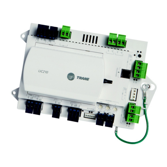
Tracer
UC210 Programmable
Controller
(VAV) Box
Only qualified personnel should install and service the equipment. The installation, starting up, and servicing of heating, ventilating, and air-
conditioning equipment can be hazardous and requires specific knowledge and training. Improperly installed, adjusted or altered equipment
by an unqualified person could result in death or serious injury. When working on the equipment, observe all precautions in the literature and
on the tags, stickers, and labels that are attached to the equipment.
March 2016
Variable-Air-Volume
SAFETY WARNING
BAS-SVX62E-EN
Advertisement
Table of Contents
Troubleshooting

Related Manuals for Trane Tracer UC210


Summary of Contents for Trane Tracer UC210
- Page 1 Installation, Operation, and Programming ® Tracer UC210 Programmable Variable-Air-Volume Controller (VAV) Box SAFETY WARNING Only qualified personnel should install and service the equipment. The installation, starting up, and servicing of heating, ventilating, and air- conditioning equipment can be hazardous and requires specific knowledge and training. Improperly installed, adjusted or altered equipment by an unqualified person could result in death or serious injury.
- Page 2 Introduction Warnings, Cautions, and Notices Safety advisories appear throughout this manual as required. Your personal safety and the proper operation of this machine depend upon the strict observance of these precautions. The three types of advisories are defined as follows: Indicates a potentially hazardous situation which, if not avoided, could result in WARNING death or serious injury.
- Page 3 Introduction Copyright This document and the information in it are the property of Trane, and may not be used or reproduced in whole or in part without written permission. Trane reserves the right to revise this publication at any time, and to make changes to its content without obligation to notify any person of such revision or change.
-
Page 4: Table Of Contents
............25 Tracer UC210 Controller Points and Parameters . - Page 5 VAV Modulating Hot Water Failure ......64 Trane/Honeywell Proportional Valve Check Out ....65 Appendix: Typical Trane Factory Wiring Diagrams .
-
Page 6: Overview
(DDC). This controller can be installed as a factory or field device. When this controller is factory installed on Trane™ variable-air-volume (VAV) terminal units, the factory will download the unit with the appropriate VAV programs and configuration settings for the unit. -
Page 7: Controller Specifications And Dimensions
Overview Controller Specifications and Dimensions Table 1. Controller storage, operating, and compliance information Storage Temperature: -40°F to 185°F (-40°C to 85°C) Humidity: 5% to 95% (non-condensing) Operating Temperature: -40°F to 158°F (-40°C to 70°C) Humidity: 5% to 95% (non-condensing) 20-4–27.6 Vac, (24 Vac ±15% nominal, 50–60 Hz, 10.5 VA plus 1 VA per 20mA of 24 VDC load plus Power: 12 VA maximum per binary load. - Page 8 Overview Figure 2. Dimensions (without Actuator) 120.0 mm U C 210 (4.72 in.) 251.4 mm (9.90 in.) Figure 3. Dimensions (Trane VAV Factory Version) 114.3 mm (4.50 in.) 155.6 mm (6.13 in.) BAS-SVX62E-EN...
-
Page 9: Shipping And Storage
Feature Description The UC210 controller allows VAV units to communicate on a BACnet MS/TP link and is compatible with the latest generation of Trane Controller Interface Flexibility: controls. This controller can operate in standalone mode, peer-to-peer with one or more other units, or when connected to a Tracer SC or a 3rd party building automation system that supports BACnet. -
Page 10: Controller Comparisons
Comparison of UC210/UC400 to VV550/551 and VAV4.2 Tracer UC210/UC400 Tracer VV550/VV551 VAV 4.2 Supports BACnet. Supports LonTalk. Supports Trane proprietary Comm4 or Comm3. No local CO sensor input. Uses only a communicated Local CO sensor input is available. Local CO sensor input is available. -
Page 11: Device Connections
Overview Device Connections The following table provides information about the types of device connections. Table 4. Device connections Connection Quantity Types Range Notes Temperature 10 kthermistor AI1 to AI3 can be configured for timed override Analog input capability. Setpoint 189 to 889 (AI1 to AI3) Resistive 100 ... -
Page 12: Device Inputs/Outputs
Overview Device Inputs/Outputs Below is a list of device inputs and outputs. • A twisted/shielded communication link • Zone sensor • Occupancy sensor (optional) • Discharge Air Temperature (DAT) • sensor • 24 Vac, Class II power Table 5 provides details for each type input/output. Table 5. -
Page 13: Wiring Installation
Wiring Installation This section provides wiring guideline information about the following: • “UC210 Controller Pre-power Check-out” • “UC210 Controller Power Wiring, ” p. 14 • “BACnet MS/TP Communication Link, ” p. 16 • “Application Wiring, ” p. 21 UC210 Controller Pre-power Check-out Carefully follow the check-out procedures below and read all warnings and notices. -
Page 14: Uc210 Controller Power Wiring
Wiring Installation UC210 Controller Power Wiring The following section provides wiring guidelines for powering the UC210 controller. WARNING Hazardous Voltage! Disconnect all electric power, including remote disconnects before servicing. Follow proper lockout/tagout procedures to ensure the power can not be inadvertently energized. Failure to disconnect power before servicing could result in death or serious injury. - Page 15 • 0.34 VA including actuator draw) • Total • 9.2 VA (Plus air damper draw) With a Trane F Series Box: 13.2 VA Total (a) See device connected to DC supply for current draw. • Replace the control box cover after field wiring to prevent any electromagnetic interference.
-
Page 16: Bacnet Ms/Tp Communication Link
Use 18 AWG Trane purple-shielded communication wire for BACnet installations. • Link limit of 4,000 ft and 60 devices maximum (without a repeater). • Use a Trane BACnet termination on each end of the link. • Use daisy chain topology (refer to Figure 4, p. -
Page 17: Wiring Best Practices
Wiring Installation Figure 4. BACnet MS/TP Link Wiring Tracer SC Trane BACnet terminator Trane BACnet terminator UC210 UC210 Zone Zone Sensor Sensor Wiring Best Practices To ensure proper network communication, follow the recommended wiring and best practices below when installing communication wire: •... -
Page 18: Setting Up The Uc210 Controller On A Bacnet Link
Wiring Installation Setting Up the UC210 Controller on a BACnet Link Observe the following when setting up the UC210 controller on a BACnet link. • Use 18 AWG shielded communication wire for BACnet MS/TP installations. • Limit BACnet MS/TP wiring links to 4,000 ft. There is a maximum of 60 devices per link (without a repeater). -
Page 19: Bacnet Networks Without A Tracer Sc System Controller
It can be soft set using Tracer TU service tool. If the BACnet Device ID is set using Tracer TU service tool, the rotary address dials only affect the MAC Address, they do not affect the BACnet Device ID. For more details, refer to the Tracer UC210 Controller BACnet Protocol Implementation Conformance Statement (PICS) [BAS-PRG014]. -
Page 20: Wiring Requirements
Wiring Installation Wiring Requirements To ensure proper operation of the UC210 controller, install the power supply circuit in accordance with the following guidelines: • The controller must receive AC power from a dedicated power circuit. Important: Failure to comply may cause the controller to malfunction. •... -
Page 21: Power On Check
Wiring Installation Power On Check 1. Verify that the 24 Vac connector and the chassis ground are properly wired. 2. Remove the lockout/tagout from the line voltage power to the electrical cabinet. 3. Energize the transformer to apply power to the UC210 controller. 4. - Page 22 If local codes require enclosed conductors, install the zone sensor wires in the conduit. • Refer to “Appendix: Typical Trane Factory Wiring Diagrams, ” p. Important: Control wires and power conductors can never be near each other (except at 90 degrees). Do not run power wired through same conduit as signal wires.
-
Page 23: Duct Temperature Sensor Wiring
Maximum wire length 1,000 ft. (300 m). • Refer to “Appendix: Typical Trane Factory Wiring Diagrams, ” p. 67 and to the Wireless Zone Sensors for Models WTS, WZS, and WDS Installation, Operation and Maintenance Manual (BAS-SVX04) for zone sensor installation instructions and terminal connections. - Page 24 Wiring Installation Occupancy Binary Input The occupancy binary input can be configured as normal open (NO) or normal closed (NC). Occupied is the normal state and the initial state at power-up and after a reset. Unoccupied is the other state. If the binary input is set as Out of Service, the default occupancy mode is occupied. Binary Output Wiring Binary outputs that are required for unit operation are factory wired and commissioned.
-
Page 25: Controller Leds
Controller LEDs This section describes how to verify and interpret the UC210 controller LEDs and safely operate the controller. LEDs are used to provide controller serviceability. The UC210 controller has the following LEDs located on the front (refer to Figure 9 Table 8, p. - Page 26 Controller LEDs Table 8. LED Activities and Troubleshooting Tips Indication and Troubleshooting LED Name Activities Tips Notes Shows solid green when the unit is Indicates normal operation. powered and no alarm exists. Shows blinking green during a device Indicates normal operation. reset or firmware download.
-
Page 27: Tracer Uc210 Controller Points And Parameters
Note: Example based on a UC210 configured for Space Temperature Control. The Tracer TU service tool will launch and display the status of the Tracer UC210 controller. The Unit Summary screen arranges relevant status information under the Operating Status, Space, Ventilation, and Outputs expanding boxes. -
Page 28: Analog, Binary, And Multistate Screens
• Space Temperature (Active) Setpoint: The active (or actual) setpoint currently used by the Tracer UC210 controller. Can be either Heating or Cooling depending on operating mode. • Space Temperature Setpoint BAS: Shows the setpoint being communicated to the VAV unit from a BAS system. -
Page 29: Controller Status Screen
Controller Status Screen Program The Tracer UC210 controller has up to three (3) TGP2 programs downloaded and defined in the factory as part of the factory commissioning process. The three programs are a base program for damper control, fan, and reheat control. When looking at programming section of Controller Status tab, operation of these programs can be monitored. -
Page 30: Setup Parameters Screen
Typically, it is not necessary to change this value. For Trane units, the nominal airflow and unit flow gain are based on unit size and are not adjustable. The default unit flow gain for generic VAV boxes is 1.0. - Page 31 Tracer UC210 Controller Points and Parameters Flow Setpoints Setup • Airflow Setpoint Minimum: Although the UCM will read flow down to 5% of cataloged, the range of MIN FLOW settings is 0% or 10% to 100% of cataloged. The UCM will not drive its flow below this minimum flow value under normal operating conditions while in the cool mode.
-
Page 32: Commissioning Screen
Calibrate Air Valve (Start Button): Displays the Calibrate Air Valve dialog box. Use this air balancing tool to perform a basic two-point air balance for the Tracer UC210 controller. See the Tracer TU Help for Programmable Controllers (“Configuring and Commissioning Equipment”... -
Page 33: Configuration Screen
Profile: This allows for selection between three operational programs. The three programs are Space Temperature, Ventilation Flow, and Flow Tracking. • Box Size: Used to select a Trane F-style box size or Generic Box. • Air Damper Opens: Chose between Clockwise and Counter-Clockwise damper rotation to open the damper. - Page 34 Tracer UC210 Controller Points and Parameters • Location of Reheat: Choices are Local and Remote. If Both is selected for Valve Control Type, this is used to select the location of the 2-Position valve.There is an additional binary value point to select whether local or remote reheat has priority.
-
Page 35: Calibration, Operation Modes, And Control
Calibration, Operation Modes, and Control This section provides information about the following: • “Calibration” • “Occupancy Modes, ” p. 35 • “Space Temperature Control (STC) for Single Duct and Fan-powered Units, ” p. 37 • “Ventilation Flow Control (VFC), ” p. 45 •... -
Page 36: Unoccupied Mode
Calibration, Operation Modes, and Control Unoccupied Mode Unoccupied mode, known as night setback, is the normal operating mode for unoccupied spaces or nighttime operation. Unoccupied setpoints enable or disable occupied space temperature control. When the controller is in the unoccupied mode, and configured for space temperature control, the controller attempts to keep the space temperature between the active unoccupied heating setpoint and the active unoccupied cooling setpoint. -
Page 37: Space Temperature Control (Stc) For Single Duct And Fan-Powered Units
Calibration, Operation Modes, and Control Space Temperature Control (STC) for Single Duct and Fan-powered Units Single Duct Units Space Temperature Control Mode Space temperature control is one of three supported control algorithms (the other two supported control algorithms are “Ventilation Flow Control (VFC), ” p. 45 “Flow Tracking (FTC), ”... - Page 38 Calibration, Operation Modes, and Control All units have a modulating air valve that is used to control how much air is flowing through the diffusers and into the space. By modulating the volume of airflow, the unit heating capacity is modulated.
- Page 39 Airflow Setpoint Minimum Local Heat. Refer to the equipment catalog for Trane F-Style VAV boxes for minimum airflow settings based on box inlet size and heating element kW.
- Page 40 When reheat is de-energized, the cooling Airflow Minimum Setpoint is enforced. The Trane VAV unit's SCR electric heater module takes a 0-to-10 Vdc control signal from AO2. Any signal less than 0.2 Vdc, and the heater is turned off. For a signal between 0.2 and 10 Vdc, the heater is on and modulated up to 100% capacity.
- Page 41 Calibration, Operation Modes, and Control Table 9. Local Heat Only With No Fan Present Configuration Method of Control Local Remote Stage 1 Stage2 Stage 3 Local thermostatic: Local thermostatic: Local thermostatic: • On: Zt < HSP • On: Zt <HSP - 1°F (0.56°C) •...
- Page 42 Calibration, Operation Modes, and Control Table 10. Local Heat Only With Parallel Fan Present (continued) Configuration Method of Control Local Remote Fan Stage 1 Stage 2 Stage 3 Local thermostatic: Local thermostatic: • On: Zt < HSP • On: Zt < HSP - 1°F (0.56°C) Not applicable Fan and On/Off •...
-
Page 43: Fan-Powered Units
Calibration, Operation Modes, and Control space temperature is below the active heating setpoint and the amount of time that the space temperature has been below the active heating setpoint. If the discharge air temperature reaches the Discharge Air Temperature Design Setpoint, the air valve opens further and modulates between Airflow Setpoint Reset Minimum Local Heat and Airflow Setpoint Reset Maximum Local Heat to maintain space temperature at the active heating setpoint, while the water valve modulates to maintain discharge air temperature at the... - Page 44 Calibration, Operation Modes, and Control Parallel Fan The parallel fan is the first stage of heat. When the supply air temperature is cold, the parallel fan: • Cycles ON as the first stage of heat during occupied mode or occupied standby mode. •...
-
Page 45: Ventilation Flow Control (Vfc)
Calibration, Operation Modes, and Control Ventilation Flow Control (VFC) Ventilation flow control is applied to a VAV terminal and used to temper cold outdoor air (OA) that is brought into a building for ventilation purposes. The tempered air is intended to supply an air handler unit (AHU), which provides comfort control to the zones it serves. - Page 46 Calibration, Operation Modes, and Control Staged Electric Reheat Control Units that are equipped with electric reheat should be sized so that the maximum temperature rise across the heating elements is from 40°F to 48°F (4.44°C to 8.88°C); it should never exceed 50°F (10°C) for safety reasons.
- Page 47 Calibration, Operation Modes, and Control Table 12. Unoccupied VFC Control, Freeze Protection for Hot Water Reheat Controller Air Valve Hot Water Valve Operation Position Condition Position Networked and Communicated supply air temperature greater than configured outdoor air low limit. Closed valid Closed no communicated...
-
Page 48: Flow Tracking (Ftc)
Calibration, Operation Modes, and Control Flow Tracking (FTC) Two (2) UC210 controllers work together to provide flow tracking control (refer to the illustration below). The space temperature controller (STC) Discharge Air Flow is communicated to the flow tracking controller and is reported as Air Flow Setpoint BAS. Note: This must be set up on the Tracer SC using either a global reference or TGP2 program. -
Page 49: Troubleshooting
Troubleshooting This section provides information about the following: • “Diagnostics” • “Troubleshooting Procedures, ” p. 50 WARNING Live Electrical Components! During installation, testing, servicing, and troubleshooting of this product, it may be necessary to work with live electrical components. Have a qualified licensed electrician or other individual who has been properly trained in handling live electrical components perform these tasks. -
Page 50: Troubleshooting Procedures
– If no voltage, check up stream of controller to see were voltage has been interrupted. Refer to the section, “Appendix: Typical Trane Factory Wiring Diagrams, ” p. • Check for short. -
Page 51: Uc210 Controller Communication Loss
BACnet system (for example, 107, 120, and so on), whether with other Trane BACnet controls or controls from another vendor. This three-digit rotary switch setting is used as both the BACnet MAC address and the BACnet Device ID. -
Page 52: Wired Zone Sensor Failure
Troubleshooting – Connect the shield portion of the wire at the first unit controller in the link. – Tape back the shield at the end of the unit controller line. – Wire together and tape all other shields at each unit controller. •... - Page 53 Troubleshooting If the proper voltage is measured at the XFMR 24 Vac input and , and there is no voltage at AI1 and , replace the UC210 controller. • Verify that the zone sensors are not shorted out. Check the resistance across the wires. Disconnect wires from the UC210 controller and zone sensor, ensuring that the ends are not touching each other, and then measure resistance.
-
Page 54: Wired Zone Sensor Setpoint Failure
Troubleshooting Wired Zone Sensor Setpoint Failure WARNING Hazardous Service Procedures! The maintenance and troubleshooting procedures recommended in this section of the manual could result in exposure to electrical, mechanical or other potential safety hazards. Always refer to the safety warnings provided throughout this manual concerning these procedures. When possible, disconnect all electrical power including remote disconnect and discharge all energy storing devices such as capacitors before servicing. -
Page 55: Airflow Sensor Failure
To calibrate: c. Connect to the UC210 controller with Tracer TU service tool. d. Turn the central air handler OFF . If this is not possible, Trane recommends pulling the transducer tubes off during the calibration process to simulate this. - Page 56 • Poor inlet configuration. – Trane recommends 1½-duct diameters of straight duct before the inlet of the box (a 12-inch box should have 18 inches of straight run duct before the inlet). •...
-
Page 57: Supply/Discharge Air Temperature Sensor Failure
Troubleshooting Supply/Discharge Air Temperature Sensor Failure WARNING Hazardous Service Procedures! The maintenance and troubleshooting procedures recommended in this section of the manual could result in exposure to electrical, mechanical or other potential safety hazards. Always refer to the safety warnings provided throughout this manual concerning these procedures. When possible, disconnect all electrical power including remote disconnect and discharge all energy storing devices such as capacitors before servicing. -
Page 58: Co2 Sensor Failure
After measuring the proper voltage at incoming power, and there is no VDC output at UI2 and , replace sensor. If there is no voltage, check up stream of controller to see were voltage has been interrupted. Refer to the section, “Appendix: Typical Trane Factory Wiring Diagrams, ” BAS-SVX62E-EN... -
Page 59: Vav Damper Failure
– If no voltage, check up stream of controller to see were voltage has been interrupted. Refer to the section, “Appendix: Typical Trane Factory Wiring Diagrams, ” p. • Actuator motor has failed. -
Page 60: Vav Series Fan Failure
Troubleshooting with a digital multi-meter (DMM). To check state of the output with a DMM, the output must me loaded with a 12VA max load. For example, a fan relay. TRIACs can be checked by purchasing a 24 Vac LED and connecting to the TRIAC output. If the 24 Vac LED does not light up, replace the UC210 controller. -
Page 61: Vav Parallel Fan Failure
Troubleshooting NOTICE: Equipment Damage! The UC210 controller outputs are switched to ground. Do not jumper 24 Vac to binary output TRIAC(s) because damage will occur. • After all checks have been completed, check motor fan winding integrity and bearing failure. VAV Parallel Fan Failure WARNING Hazardous Service Procedures! -
Page 62: Psc (Permanent Split Capacitor) Variable Speed Motor Check
If the PSC Variable speed motor control does not change the motor speed, check the following: • Wires connected improperly. Refer to the section, “Appendix: Typical Trane Factory Wiring Diagrams, ” p. • Check voltage selection switch on side of variable speed motor control. It should be set for motor voltage. -
Page 63: Vav Electric Heat Stage Failure
Troubleshooting – The voltage selection switch still remains fully clockwise. • Turn motor speed control potentiometer slowly, fully clockwise. The motor should smoothly ramp to full speed. • If the PSC motor speed controller fails, replace it. VAV Electric Heat Stage Failure WARNING Live Electrical Components! During installation, testing, servicing and troubleshooting of this product, it may be necessary... -
Page 64: Vav Modulating Hot Water Failure
Troubleshooting VAV Modulating Hot Water Failure WARNING Live Electrical Components! During installation, testing, servicing and troubleshooting of this product, it may be necessary to work with live electrical components. Have a qualified licensed electrician or other individual who has been properly trained in handling live electrical components perform these tasks. -
Page 65: Trane/Honeywell Proportional Valve Check Out
Troubleshooting Trane/Honeywell Proportional Valve Check Out There are two failures can result in over conditioning the space: • Cartridge failure • Actuator failure Cartridge Failure Cartridge failure will occur if the actuator is driven CLOSED, but there is an 1/8 inch or greater of movement in the indicator, or if the piston has not returned up past the ‘A’... - Page 66 Troubleshooting – Check for correct binary outputs. It should have 24 Vac. If it does not, measure the power input to XFMR 24 Vac input and of the UC210 controller. The supply voltage should be between 20.4 to 27.6 Vac (24 Vac cataloged). However, voltages at either extreme may result in system instability.
-
Page 67: Appendix: Typical Trane Factory Wiring Diagrams
Appendix: Typical Trane Factory Wiring Diagrams Figure 13. UC210 Controller Wiring for Single Duct Unit BAS-SVX62E-EN... - Page 68 Appendix: Typical Trane Factory Wiring Diagrams Figure 14. UC210 Controller Wiring for Fan Powered Unit BAS-SVX62E-EN...
-
Page 69: Additional Resources
• Engineered Smoke Control System for Tracer SC System Controller Application Guide (BAS-APG019) • Tracer UC210 Controller BACnet Protocol Implementation Conformance Statement (PICS) (BAS-PRG014) • Tracer SC System Controller Installation and Setup (BAS-SVX31) • Air Systems for Tracer SC Application Guide (BAS-APG007) •... -
Page 70: Index
Multistate Screen 28 Supply/Discharge Air Temperature Sensor BACnet MS/TP Communication Link Failure 57 Occupancy Modes 35 Application Wiring 21 Trane/Honeywell Proportional Occupied Bypass Mode 36 Valve Check Out 65 Connecting the Wires 20 Occupied Mode 35 UC210 Controller Power On Check 21... - Page 71 Index Unoccupied Ventilation Flow Control 47 Wiring Diagrams 67 Fan Powered Unit 68 Single Duct Unit 67 Wiring Installation Guidelines 14 UC210 Controller Power Wiring 14 UC210 Controller Pre-power Check-out 13 BAS-SVX62E-EN...
- Page 72 Our people and our family of brands—including Club Car®, Ingersoll Rand®, Thermo King® and Trane®—work together to enhance the quality and comfort of air in homes and buildings; transport and protect food and perishables; and increase industrial productivity and efficiency. We are a $13 billion global business committed to a world of sustainable progress and enduring results.