Trane Tracer UC400 Installation, Operation And Maintenance Manual
Programmable controllers for blower coil, fan coil, and unit ventilator
Hide thumbs
Also See for Tracer UC400:
- Installation, operation and maintenance manual (60 pages) ,
- Installation manual (16 pages) ,
- Installation instructions (2 pages)
Table of Contents
Advertisement
Quick Links
Installation, Operation, and Maintenance
Tracer
®
Programmable Controllers
For Blower Coil, Fan Coil, and Unit Ventilator
Only qualified personnel should install and service the equipment. The installation, starting up, and servicing of heating, ventilating, and air-conditioning
equipment can be hazardous and requires specific knowledge and training. Improperly installed, adjusted or altered equipment by an unqualified person
could result in death or serious injury. When working on the equipment, observe all precautions in the literature and on the tags, stickers, and labels that
are attached to the equipment.
April 2020
UC400/UC400–B
S S A A F F E E T T Y Y W W A A R R N N I I N N G G
B B A A S S - - S S V V X X 4 4 8 8 H H - - E E N N
Advertisement
Table of Contents

Related Manuals for Trane Tracer UC400


Summary of Contents for Trane Tracer UC400
- Page 1 Installation, Operation, and Maintenance Tracer ® UC400/UC400–B Programmable Controllers For Blower Coil, Fan Coil, and Unit Ventilator S S A A F F E E T T Y Y W W A A R R N N I I N N G G Only qualified personnel should install and service the equipment.
- Page 2 Copyright This document and the information in it are the property of Trane, and may not be used or reproduced in whole or in part without written permission. Trane reserves the right to revise this publication at any time, and to make changes to its content without obligation to notify any person of such revision or change.
-
Page 3: Table Of Contents
Table of Contents BACnet Protocol ............. . . 6 BACnet®... - Page 4 T T a a b b l l e e o o f f C C o o n n t t e e n n t t s s BACnet Networks, With or Without Tracer SC Controller ..... . . 31 Without a Tracer SC Controller .
- Page 5 T T a a b b l l e e o o f f C C o o n n t t e e n n t t s s Heat Pump Operation, 1 or 2 Circuits ......... 50 Defrost Operation.
-
Page 6: Bacnet Protocol
BACnet Protocol The Building Automation and Control Network (BACnet®) protocol is ANSI/ASHRAE Standard 135. This standard allows building automation systems or components from different manufacturers to share information and control functions. BACnet® provides building owners the capability to connect various types of building control systems or subsystems together for many uses. -
Page 7: Specifications And Dimensions
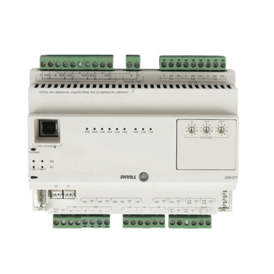
Specifications and Dimensions Table 1. UC400/UC400–B Specifications Storage Temperature: –48°F to 203°F (–44°C to 95°C) Relative Humidity: Between 5% and 95% (non-condensing) Operating Temperature: –40°F to 158°F (–40°C to 70°C) Humidity: Between 5% and 95% (non-condensing) Input Power: 20.4–27.6 Vac (24, ±15% nominal), 50Hz to 60Hz, 24 VA (24 VA plus binary output loads for a maximum of 12 VA for each binary output) Mounting Weight of Supporting mounting surface: must be 0.80 lb. - Page 8 S S p p e e c c i i f f i i c c a a t t i i o o n n s s a a n n d d D D i i m m e e n n s s i i o o n n s s Figure 1.
-
Page 9: Device Connections
Device Connections The following table provides details of the hardware termination configuration options. The hardware terminations are pre-configured for proper equipment operation for blower coil/fan coil applications. W W A A R R N N I I N N G G L L i i v v e e E E l l e e c c t t r r i i c c a a l l C C o o m m p p o o n n e e n n t t s s ! ! F F a a i i l l u u r r e e t t o o f f o o l l l l o o w w a a l l l l e e l l e e c c t t r r i i c c a a l l s s a a f f e e t t y y p p r r e e c c a a u u t t i i o o n n s s w w h h e e n n e e x x p p o o s s e e d d t t o o l l i i v v e e e e l l e e c c t t r r i i c c a a l l c c o o m m p p o o n n e e n n t t s s c c o o u u l l d d r r e e s s u u l l t t i i n n d d e e a a t t h h o o r r s s e e r r i i o o u u s s i i n n j j u u r r y y . - Page 10 D D e e v v i i c c e e C C o o n n n n e e c c t t i i o o n n s s Table 2. Connections (continued) Quantity Types Range Connection Notes...
-
Page 11: Additional Components
N N o o t t e e : : Additional components are not included with the UC400 Controller. Water, Discharge, and Outdoor Air Temperature Sensors Temperature sensors must be Trane 10 kΩ (at 25°C) thermistors. Entering water and discharge air inputs can use a sealed temperature sensor (part numbers 4190 1100 and 4190 1133). A discharge air temperature sensor is required for proper operation. -
Page 12: Valve And Damper Actuators
4–20 mA output, where 4 mA is 0% RH and 20 mA is 100% RH. The controller provides 24 Vdc to power the zone humidity sensor. N N o o t t e e : : As an option, the UC400 Controller can receive humidity from a Trane Air-fi™ Wireless Sensor with Humidity. -
Page 13: Typical Applications And Terminations
4-Pipe Steam/chilled Water DX Cooling DX Cooling with 2-Pipe Heating DX cCooling with 2-Pipe Steam Heat DX Heat Pump Only Tracer UC400 supports single-stage, two-stage, and modulating electric heat. Table 5. Factory Programmed Terminations Inputs/Outputs/Communication Factory Programmed Assumed Terminations Terminations... -
Page 14: Binary Inputs
T T y y p p i i c c a a l l A A p p p p l l i i c c a a t t i i o o n n s s a a n n d d T T e e r r m m i i n n a a t t i i o o n n s s Table 5. -
Page 15: Bi3; Low Coil Temp Detection
Controller receives the space temperature as a resistance signal from a 10 kΩ thermistor in a standard Trane space temperature sensor that is wired to analog input AI1. A space temperature value communicated by means of a BACnet link, can be used for controllers operating on a BAS. -
Page 16: Ai3; Local Fan Mode Input
Local Fan Mode Input AI3 functions as the local (hard wired) fan mode switch input for applications using the Trane space temperature sensor with a fan mode switch option. The various fan mode switch positions (OFF, LOW, MEDIUM, HIGH, AUTO) provide different resistances that are interpreted by the UC400 Controller. -
Page 17: Ui2; Outdoor Air Temperature
S S u u p p p p l l y y F F a a n n S S p p e e e e d d R R e e q q u u e e s s t t : : analog value point for variable speed (0-100%) fan applications, including Trane ECM engine module. - Page 18 T T y y p p i i c c a a l l A A p p p p l l i i c c a a t t i i o o n n s s a a n n d d T T e e r r m m i i n n a a t t i i o o n n s s Table 6.
-
Page 19: Uc400 Wiring Diagrams
T T y y p p i i c c a a l l A A p p p p l l i i c c a a t t i i o o n n s s a a n n d d T T e e r r m m i i n n a a t t i i o o n n s s UC400 Wiring Diagrams Figure 2. - Page 20 T T y y p p i i c c a a l l A A p p p p l l i i c c a a t t i i o o n n s s a a n n d d T T e e r r m m i i n n a a t t i i o o n n s s Figure 3.
- Page 21 T T y y p p i i c c a a l l A A p p p p l l i i c c a a t t i i o o n n s s a a n n d d T T e e r r m m i i n n a a t t i i o o n n s s Figure 4.
- Page 22 T T y y p p i i c c a a l l A A p p p p l l i i c c a a t t i i o o n n s s a a n n d d T T e e r r m m i i n n a a t t i i o o n n s s Figure 5.
- Page 23 T T y y p p i i c c a a l l A A p p p p l l i i c c a a t t i i o o n n s s a a n n d d T T e e r r m m i i n n a a t t i i o o n n s s Figure 6.
- Page 24 T T y y p p i i c c a a l l A A p p p p l l i i c c a a t t i i o o n n s s a a n n d d T T e e r r m m i i n n a a t t i i o o n n s s Figure 7.
-
Page 25: Uc400-B Wiring Diagrams
T T y y p p i i c c a a l l A A p p p p l l i i c c a a t t i i o o n n s s a a n n d d T T e e r r m m i i n n a a t t i i o o n n s s UC400–B Wiring Diagrams Figure 8. - Page 26 T T y y p p i i c c a a l l A A p p p p l l i i c c a a t t i i o o n n s s a a n n d d T T e e r r m m i i n n a a t t i i o o n n s s Figure 9.
- Page 27 T T y y p p i i c c a a l l A A p p p p l l i i c c a a t t i i o o n n s s a a n n d d T T e e r r m m i i n n a a t t i i o o n n s s Figure 10.
- Page 28 T T y y p p i i c c a a l l A A p p p p l l i i c c a a t t i i o o n n s s a a n n d d T T e e r r m m i i n n a a t t i i o o n n s s Figure 11.
- Page 29 T T y y p p i i c c a a l l A A p p p p l l i i c c a a t t i i o o n n s s a a n n d d T T e e r r m m i i n n a a t t i i o o n n s s Figure 12.
- Page 30 T T y y p p i i c c a a l l A A p p p p l l i i c c a a t t i i o o n n s s a a n n d d T T e e r r m m i i n n a a t t i i o o n n s s Figure 13.
-
Page 31: Wiring Installation
Wiring Installation The Tracer UC400 Controller can be installed on a BACnet MS/TP link, or with the Trane ® Wireless Communication Interface (WCI), which enables wireless communication. All wiring must comply with the National Electrical Code (NEC™) and local electrical codes. -
Page 32: Bacnet Ms/Tp Link Wiring
Zone Sensor Communications LINK LINK Jack Wiring LINK LINK SERVI SERVI SERVICE TOOL SERVICE TOOL Trane BACnet Terminator 1 2 3 4 1 2 3 4 1 2 3 4 24VDC 24VDC 24VDC BACnet BACnet BACnet 1 2 3 4... -
Page 33: Power Supply
W W i i r r i i n n g g I I n n s s t t a a l l l l a a t t i i o o n n Power Supply Read the following Warnings, Cautions, and Notices before proceeding. W W A A R R N N I I N N G G H H a a z z a a r r d d o o u u s s V V o o l l t t a a g g e e ! ! F F a a i i l l u u r r e e t t o o d d i i s s c c o o n n n n e e c c t t p p o o w w e e r r b b e e f f o o r r e e s s e e r r v v i i c c i i n n g g c c o o u u l l d d r r e e s s u u l l t t i i n n d d e e a a t t h h o o r r s s e e r r i i o o u u s s i i n n j j u u r r y y . -
Page 34: Connecting 24 Vac Secondary Wires
W W i i r r i i n n g g I I n n s s t t a a l l l l a a t t i i o o n n I I m m p p o o r r t t a a n n t t : : The controller must receive AC power from a dedicated power circuit. Failure to comply may cause the controller to malfunction. -
Page 35: Power On Check
W W i i r r i i n n g g I I n n s s t t a a l l l l a a t t i i o o n n the controller ground terminal and the transformer. b. -
Page 36: Led Description, Activities, And Troubleshooting
LED Description, Activities, and Troubleshooting LEDs are used to provide controller serviceability. The UC400/UC400–B has the following LEDs located on the front. Refer to the legend in the second image in the figure below for LED placements. • Marquee LED. •... - Page 37 L L E E D D D D e e s s c c r r i i p p t t i i o o n n , , A A c c t t i i v v i i t t i i e e s s , , a a n n d d T T r r o o u u b b l l e e s s h h o o o o t t i i n n g g Table 8.
- Page 38 L L E E D D D D e e s s c c r r i i p p t t i i o o n n , , A A c c t t i i v v i i t t i i e e s s , , a a n n d d T T r r o o u u b b l l e e s s h h o o o o t t i i n n g g Table 8.
-
Page 39: Sequence Of Operation
• The state of the local (hard wired) occupancy binary input BI1. • A timed override request from a Trane zone sensor. • A communicated signal from either a Tracer SC or BAS. A communicated request, from either a Tracer SC or BAS, takes precedence over local requests. -
Page 40: Unoccupied Mode
The controller is operating in the unoccupied mode. • Either the timed override ON button on the Trane zone sensor is pressed or the controller receives a communicated occupied bypass signal from a BAS. In occupied bypass mode, the controller maintains the space temperature based on the occupied heating or cooling setpoints. - Page 41 S S e e q q u u e e n n c c e e o o f f O O p p e e r r a a t t i i o o n n load decreases, the fan speed is reduced to maintain zone temperature at cooling setpoint, while cooling capacity (and/or economizer) modulates or cycles to maintain DAT at the same design setpoint as show below.
-
Page 42: Discharge Air Tempering
S S e e q q u u e e n n c c e e o o f f O O p p e e r r a a t t i i o o n n • S S i i m m p p l l i i f f i i e e d d Z Z o o n n e e C C o o n n t t r r o o l l : : if discharge air temperature failure occurs, then the UC400 Controller switches to simplified zone control algorithm, whereby, the space is controlled to the unoccupied setpoints by means of the valve modulation and a cycling fan. -
Page 43: Fan Operation
S S e e q q u u e e n n c c e e o o f f O O p p e e r r a a t t i i o o n n main hydronic valve and waits 60 minutes to attempt another sampling. If the entering water temperature value falls within the required range, it resumes normal heating/cooling operation and disables the sampling function. -
Page 44: Exhaust Control
S S e e q q u u e e n n c c e e o o f f O O p p e e r r a a t t i i o o n n Figure 19. Cooling/Heating Load Changes At high heating loads, the fan speed modulates to maintain the zone temperature at heating setpoint, while the heating capacity modulates or stages to maintain the DAT at the maximum limit. -
Page 45: Valve Operation
S S e e q q u u e e n n c c e e o o f f O O p p e e r r a a t t i i o o n n Valve Operation The UC400 Controller supports 1–, 2–modulating or 2-position valves, depending on the application. -
Page 46: Ashrae Cycle 1 Conformance
S S e e q q u u e e n n c c e e o o f f O O p p e e r r a a t t i i o o n n configured minimum position for low fan speed whenever the fan is running at low speed, regardless of the occupancy state. -
Page 47: Economizing (Free Cooling)
S S e e q q u u e e n n c c e e o o f f O O p p e e r r a a t t i i o o n n allowed to open to the occupied or occupied standby minimum damper positions. When the space temperature is between 2ºF and 3ºF below the setpoint, the damper is set between 0 and the minimum damper position. -
Page 48: Co -Based Demand Controlled Ventilation
S S e e q q u u e e n n c c e e o o f f O O p p e e r r a a t t i i o o n n -Based Demand Controlled Ventilation -based demand controlled ventilation measures the concentration of carbon dioxide (CO ) in the zone as a means to vary the outdoor airflow delivered as the population of the zone changes. -
Page 49: Dx Cooling Operation, 1 Or 2 Circuits
S S e e q q u u e e n n c c e e o o f f O O p p e e r r a a t t i i o o n n Figure 22. OA Damper Position Setpoints •... -
Page 50: Heat Pump Operation, 1 Or 2 Circuits
S S e e q q u u e e n n c c e e o o f f O O p p e e r r a a t t i i o o n n pump unit when in cooling mode (using the reversing valve). Compressor(s) are held to a minimum ON/OFF time of three (3) minutes and an inter-stage delay timer of three (3) minutes. -
Page 51: Unit Protection Strategies
In addition, a fan status switch can be connected to binary input 5 (BI5) to monitor the status of the fan for belt-driven or direct-driven units (except Trane Macon factory ECM fan motor units). The fan status switch provides feedback to the controller as follows: •... -
Page 52: Fan Off Delay
S S e e q q u u e e n n c c e e o o f f O O p p e e r r a a t t i i o o n n page or by temporarily overriding the Reset Diagnostic Request on the Tracer TU Binary Status page. -
Page 53: Output Testing
S S u u p p p p l l y y F F a a n n S S p p e e e e d d R R e e q q u u e e s s t t : : analog value point for variable speed (0-100%) fan applications, including Trane ECM engine module application. -
Page 54: Diagnostic Generated By The Uc400
O O u u t t p p u u t t T T e e s s t t i i n n g g Automatic— Non-Latching Automatic diagnostics clear automatically when the problem that generated the diagnostic is solved. - Page 55 O O u u t t p p u u t t T T e e s s t t i i n n g g Table 11. Diagnostics (continued) Diagnostic Consequences Diagnostic Type Probable Cause Entering Water Temp Failure Invalid or missing value for zone temperature.
- Page 56 O O u u t t p p u u t t T T e e s s t t i i n n g g Table 11. Diagnostics (continued) Diagnostic Consequences Diagnostic Type Probable Cause Generic AIP Failure Invalid or missing value for generic analog input. Informational •...
-
Page 57: Operational Causes And Diagnostics
Operational Causes and Diagnostics Table 12. Diagnostic Causes and Diagnostics Diagnostic Probable Cause Fan Not Energizing The wiring between the UC400 Controller outputs, fan relays, and contacts must be present and Unit Wiring correct for normal fan operation. The fan motor and relay must be checked to ensure proper operation. Failed End Device The fan turns OFF when: •... - Page 58 O O p p e e r r a a t t i i o o n n a a l l C C a a u u s s e e s s a a n n d d D D i i a a g g n n o o s s t t i i c c s s Table 12.
- Page 59 O O p p e e r r a a t t i i o o n n a a l l C C a a u u s s e e s s a a n n d d D D i i a a g g n n o o s s t t i i c c s s Table 12.
-
Page 60: Configuration And Maintenance
Use the Tracer TU Configuration Screen to create a factory configuration. N N o o t t e e : : Some modifications can be made to the Trane factory blower coil, fan coil, or unit ventilator configurations. The VAV code cannot be modified, but side programs can be added that can add to or change the sequence of operation. - Page 61 C C o o n n f f i i g g u u r r a a t t i i o o n n a a n n d d M M a a i i n n t t e e n n a a n n c c e e programs and the points they use.
- Page 62 C C o o n n f f i i g g u u r r a a t t i i o o n n a a n n d d M M a a i i n n t t e e n n a a n n c c e e configuration files, controller firmware, and TGP2 programs using the File Transfer Utility and the Backup Utility.
-
Page 63: Settings For Co 2 -Based Demand Controlled Ventilation
Settings for CO -Based Demand Controlled Ventilation The CO -based DCV sequence used in UC400 Controller is based on the sequence suggested in the ASHRAE Standard 62.1 User Manual, Appendix A. N N o o t t e e : : This sequence is intended for a fan-coil, blower-coil, and unit ventilator product that is applied as a single-zone ventilation system. - Page 64 S S e e t t t t i i n n g g s s f f o o r r C C O O - - B B a a s s e e d d D D e e m m a a n n d d C C o o n n t t r r o o l l l l e e d d V V e e n n t t i i l l a a t t i i o o n n = concentration of CO in the outdoor air, ppm 2outdoors...
- Page 65 S S e e t t t t i i n n g g s s f f o o r r C C O O - - B B a a s s e e d d D D e e m m a a n n d d C C o o n n t t r r o o l l l l e e d d V V e e n n t t i i l l a a t t i i o o n n Figure 23.
- Page 66 S S e e t t t t i i n n g g s s f f o o r r C C O O - - B B a a s s e e d d D D e e m m a a n n d d C C o o n n t t r r o o l l l l e e d d V V e e n n t t i i l l a a t t i i o o n n the damper), this is less accurate than setting the OA damper position setpoints based on measured outdoor airflow.
-
Page 67: Resources
Resources • Tracer UC400 Programmable Controller Installation, Operation, and Maintenance Manual (BAS-SVX20-EN). • Tracer UC400 Programmable Controller Installation Sheet (X39641064-01). • Tracer TU Online Help Tracer TU Service Tool Getting Started Guide (TTU-SVN01-EN). • Tracer SC System Controller Installation and Setup (BAS-SVX31-EN). - Page 68 For more information, please visit trane.com or tranetechnologies.com. Trane has a policy of continuous product and product data improvements and reserves the right to change design and specifications without notice. We are committed to using environmentally conscious print practices.