Trane Tracer UC600 Integration Manual
For packaged outdoor air unit
Hide thumbs
Also See for Tracer UC600:
- Installation manual (56 pages) ,
- Installation, operation and maintenance manual (84 pages)
Table of Contents
Advertisement
Quick Links
Integration Guide
Tracer® ® UC600 Programmable
Controller
for Packaged Outdoor Air Unit
Only qualified personnel should install and service the equipment. The installation, starting up, and servicing of heating, ventilating, and air-conditioning
equipment can be hazardous and requires specific knowledge and training. Improperly installed, adjusted or altered equipment by an unqualified person
could result in death or serious injury. When working on the equipment, observe all precautions in the literature and on the tags, stickers, and labels that
are attached to the equipment.
July 2020
S S A A F F E E T T Y Y W W A A R R N N I I N N G G
B B A A S S - - S S V V P P 1 1 8 8 D D - - E E N N
Advertisement
Table of Contents

Related Manuals for Trane Tracer UC600


Summary of Contents for Trane Tracer UC600
- Page 1 Integration Guide Tracer® ® UC600 Programmable Controller for Packaged Outdoor Air Unit S S A A F F E E T T Y Y W W A A R R N N I I N N G G Only qualified personnel should install and service the equipment. The installation, starting up, and servicing of heating, ventilating, and air-conditioning equipment can be hazardous and requires specific knowledge and training.
- Page 2 CFCs and HCFCs such as saturated or unsaturated HFCs and HCFCs. Important Responsible Refrigerant Practices Trane believes that responsible refrigerant practices are important to the environment, our customers, and the air conditioning industry. All technicians who handle refrigerants must be certified according to local rules.
- Page 3 N N o o n n - - T T r r a a n n e e p p e e r r s s o o n n n n e e l l s s h h o o u u l l d d a a l l w w a a y y s s f f o o l l l l o o w w l l o o c c a a l l r r e e g g u u l l a a t t i i o o n n s s . . Copyright This document and the information in it are the property of Trane, and may not be used or reproduced in whole or in part without written permission. Trane reserves the right to revise this publication at any time, and to make changes to its content without obligation to notify any person of such revision or change.
-
Page 4: Table Of Contents
Table of Contents Overview ..............5 BACnet Protocol . -
Page 5: Overview
BACnet® defines a number of application services that are used to interact with objects in a BACnet® device. BACnet Testing Laboratory (BTL) Certification The UC600 is BTL certified as a B-AAC profile device. A complete list of Trane certified devices is available at www.bacnetinternational.org. BAS-SVP18D-EN... -
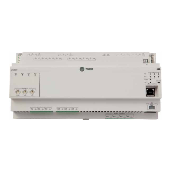
Page 6: Uc600 Rotary Switches And Leds
UC600 Rotary Switches and LEDs This section provides information about the UC600 rotary switches and LED displays. Rotary Switches There are three (3) rotary switches on the front of the UC600. They are used to set the BACnet MS/TP network address and BACnet Device ID. Refer to the section, “MS/TP MAC Address,”... -
Page 7: 24 Vac Measurement
U U C C 6 6 0 0 0 0 R R o o t t a a r r y y S S w w i i t t c c h h e e s s a a n n d d L L E E D D s s Figure 2. - Page 8 U U C C 6 6 0 0 0 0 R R o o t t a a r r y y S S w w i i t t c c h h e e s s a a n n d d L L E E D D s s BAS-SVP18D-EN...
-
Page 9: Configuring The Uc600
Configuring the UC600 The UC600 BACnet configuration settings can be modified with either the Trane BACnet Setup Tool or the Tracer TU service tool. The BACnet setup tool can only be used to configure the baud rate, software device ID, and device units of measure. Tracer TU provides complete configuration and programming capabilities. -
Page 10: Configuration
MS/TP master device as zero (0) to 127. All Trane devices are master devices. When a Tracer SC device is present on the MS/TP network, Trane restricts the use of the zero (0) MAC address. This address is assigned to the Tracer SC and cannot be changed. All other BACnet MS/TP master devices, including the UC600, must have a MAC addresses within the range of 1 to 127. -
Page 11: Tracer Sc Bas Integration
C C o o n n f f i i g g u u r r i i n n g g t t h h e e U U C C 6 6 0 0 0 0 Using this method, the Device ID is limited to the range of 0 to 127. When there is a need to set the Device ID to a value greater than 127, software configuration must be used. -
Page 12: Initiating System Control
C C o o n n f f i i g g u u r r i i n n g g t t h h e e U U C C 6 6 0 0 0 0 Initiating System Control By default, the following BACnet points are put out of service and need to be put into service to be used, if required: •... -
Page 13: Bacnet Data Points And Configuration Property Definitions
VAV, fan coils, small air handlers, and Product Description: many other applications. In addition, this controller can be used as a BACnet MS/ TP communications interface for Trane IntelliPak™, ReliaTel™, and CH530 controls. Standardized Device Profile (Annex L) -
Page 14: Segmentation Capability
B B A A C C n n e e t t D D a a t t a a P P o o i i n n t t s s a a n n d d C C o o n n f f i i g g u u r r a a t t i i o o n n P P r r o o p p e e r r t t y y D D e e f f i i n n i i t t i i o o n n s s Trending Description Supported BIBB Trending-Automated Trend Retrieval-B (T-ATR-B) - Page 15 B B A A C C n n e e t t D D a a t t a a P P o o i i n n t t s s a a n n d d C C o o n n f f i i g g u u r r a a t t i i o o n n P P r r o o p p e e r r t t y y D D e e f f i i n n i i t t i i o o n n s s Table 2.
- Page 16 B B A A C C n n e e t t D D a a t t a a P P o o i i n n t t s s a a n n d d C C o o n n f f i i g g u u r r a a t t i i o o n n P P r r o o p p e e r r t t y y D D e e f f i i n n i i t t i i o o n n s s Table 2.
- Page 17 B B A A C C n n e e t t D D a a t t a a P P o o i i n n t t s s a a n n d d C C o o n n f f i i g g u u r r a a t t i i o o n n P P r r o o p p e e r r t t y y D D e e f f i i n n i i t t i i o o n n s s Table 2.
-
Page 18: Data Link Layer Options, Device Address Binding, Network Options, And Character Sets
B B A A C C n n e e t t D D a a t t a a P P o o i i n n t t s s a a n n d d C C o o n n f f i i g g u u r r a a t t i i o o n n P P r r o o p p e e r r t t y y D D e e f f i i n n i i t t i i o o n n s s Data Link Layer Options, Device Address Binding, Network Options, and Character Sets Data Link Layer Description Supported... -
Page 19: Object And Diagnostic Data Points
Object and Diagnostic Data Points For quick reference, the following tables are listed and sorted two different ways. Table 3, p. 19 through Table 9, p. 25 are listed by input/output type and sorted by object type. Table 10, p. 26 sorted by Object Name. - Page 20 O O b b j j e e c c t t a a n n d d D D i i a a g g n n o o s s t t i i c c D D a a t t a a P P o o i i n n t t s s Table 4.
- Page 21 O O b b j j e e c c t t a a n n d d D D i i a a g g n n o o s s t t i i c c D D a a t t a a P P o o i i n n t t s s Table 5.
- Page 22 O O b b j j e e c c t t a a n n d d D D i i a a g g n n o o s s t t i i c c D D a a t t a a P P o o i i n n t t s s Table 5.
- Page 23 O O b b j j e e c c t t a a n n d d D D i i a a g g n n o o s s t t i i c c D D a a t t a a P P o o i i n n t t s s Table 6.
- Page 24 O O b b j j e e c c t t a a n n d d D D i i a a g g n n o o s s t t i i c c D D a a t t a a P P o o i i n n t t s s Table 8.
- Page 25 O O b b j j e e c c t t a a n n d d D D i i a a g g n n o o s s t t i i c c D D a a t t a a P P o o i i n n t t s s Table 8.
- Page 26 O O b b j j e e c c t t a a n n d d D D i i a a g g n n o o s s t t i i c c D D a a t t a a P P o o i i n n t t s s Table 9.
- Page 27 O O b b j j e e c c t t a a n n d d D D i i a a g g n n o o s s t t i i c c D D a a t t a a P P o o i i n n t t s s Table 10.
- Page 28 O O b b j j e e c c t t a a n n d d D D i i a a g g n n o o s s t t i i c c D D a a t t a a P P o o i i n n t t s s Table 10.
- Page 29 O O b b j j e e c c t t a a n n d d D D i i a a g g n n o o s s t t i i c c D D a a t t a a P P o o i i n n t t s s Table 10.
- Page 30 O O b b j j e e c c t t a a n n d d D D i i a a g g n n o o s s t t i i c c D D a a t t a a P P o o i i n n t t s s Table 10.
- Page 31 O O b b j j e e c c t t a a n n d d D D i i a a g g n n o o s s t t i i c c D D a a t t a a P P o o i i n n t t s s Table 10.
- Page 32 O O b b j j e e c c t t a a n n d d D D i i a a g g n n o o s s t t i i c c D D a a t t a a P P o o i i n n t t s s Table 10.
-
Page 33: Alarming
Alarming The UC600 unit for Packaged Outside Air Units has several objects used for communicating alarms to the system. Table 11. Alarm objects Object Type Object Name Description Notification Class Normal open input. ESTOP • 0 = Normal • 1 = ESTOP Normal open input. -
Page 34: Additional Resources
• Tracer Expansion Module Installation, Operation, and Maintenance (BAS-SVX046*-EN) • Tracer® UC600 Programmable Controller Installation, Operation, and Maintenance Manual (BAS-SVX45*-EN) N N o o t t e e : : For further assistance, contact your local Trane sales office. BAS-SVP18D-EN... - Page 35 N N o o t t e e s s BAS-SVP18D-EN...
- Page 36 For more information, please visit trane.com or tranetechnologies.com. Trane has a policy of continuous product and product data improvements and reserves the right to change design and specifications without notice. We are committed to using environmentally conscious print practices.