Endress+Hauser Micropilot FMR60 Functional Safety Manual
Free space radar for liquids and bulk solids with 4 to 20 ma output signal
Hide thumbs
Also See for Micropilot FMR60:
- Technical information (72 pages) ,
- Safety instructions (64 pages) ,
- Technical information (68 pages)

Related Manuals for Endress+Hauser Micropilot FMR60


Summary of Contents for Endress+Hauser Micropilot FMR60
- Page 1 Products Solutions Services SD01950F/00/EN/01.17 71355048 Special Documentation Micropilot FMR60/62/67 Functional Safety Manual Free space radar for liquids and bulk solids with 4 to 20 mA output signal...
-
Page 2: Table Of Contents
Micropilot FMR60/62/67 Table of contents Declaration of Conformity ....3 Other safety-related characteristic values ... . . -
Page 3: Declaration Of Conformity
Micropilot FMR60/62/67 Declaration of Conformity A0033673 Endress+Hauser... - Page 4 Micropilot FMR60/62/67 A0033675 Endress+Hauser...
-
Page 5: Other Safety-Related Characteristic Values
Micropilot FMR60/62/67 Other safety-related Characteristics as per IEC 61508 Value characteristic values System reaction time as per DIN EN 61298-2 In "Increased safety mode" • for "Medium type = Liquid": <19 s • for "Medium type = Solid": < 300 s In "Expert mode"... -
Page 6: Document Information
• General information about functional safety: SIL • General information about SIL is available: In the Download Area of the Endress+Hauser Internet site: www.de.endress.com/SIL Using this document Information on the document structure For the arrangement of the parameters as per the Operation menu, Setup menu, Diagnostics... -
Page 7: Supplementary Device Documentation
Micropilot FMR60/62/67 Supplementary device Documentation Comment documentation Technical Information: The documentation is available on the Internet: • TI01302F/00 (FMR60) → www.endress.com • TI01303F/00 (FMR62) • TI01304F/00 (FMR67) Operating Instructions The documentation is available on the Internet: • BA01618F/00 (FMR60) → www.endress.com •... -
Page 8: Permitted Devices Types
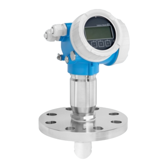
Micropilot FMR60/62/67 Permitted devices types The details pertaining to functional safety in this manual relate to the device versions listed below and are valid as of the specified software and hardware version. Unless otherwise specified, all subsequent versions can also be used for safety functions. A modification process according to IEC 61508 is applied for device changes. -
Page 9: Safety Function
Micropilot FMR60/62/67 Safety function Definition of the safety The device' s safety functions are: function Safety function (level measurement) • Maximum point level monitoring (overfill protection) • Minimum point level monitoring (dry run protection) • Level range monitoring The safety functions include level measurement of a liquid or bulk solid. - Page 10 Micropilot FMR60/62/67 Safety related error Explanation Implications for the Implications for the safety related output measuring uncertainty signal (Position, see figure → 10) No device error Safe: None 1 Is within the No error specification (see TI, BA, ...) λ...
-
Page 11: Use In Protective Systems
Micropilot FMR60/62/67 Use in protective systems Device behavior during Device behavior in SIL-locked state operation After SIL locking, additional diagnostics are active and critical parameters in the safety path are set to safe values (→ 15). Therefore, the behavior of the device in the "SIL-locked state"... -
Page 12: Parameter Configuration For Safety-Related Applications
Micropilot FMR60/62/67 Exceptions: Error code Current output (message type) Note M272 ≥21.0 mA or ≤3.6 mA Main electronic failure C484 ≥21.0 mA or ≤3.6 mA Simulation failure mode S942 ≥21.0 mA or ≤3.6 mA In safety distance The error codes are listed in the Operating Instructions. - Page 13 Micropilot FMR60/62/67 Locking in "Increased safety mode" To commission the device, carry out and document the following steps in the order shown (→ 30). Reset device. This resets all parameters to defined values. Navigate to: Setup → Advanced setup → Administration...
- Page 14 Micropilot FMR60/62/67 Setting Set write protection = enter the locking code again (WHG: 7450; SIL: 7452; SIL and WHG: 7454). Check the locking status after performing SIL locking. Navigate to: Setup → Advanced setup Setting Locking status = SIL locked must be confirmed by selecting "".
- Page 15 Micropilot FMR60/62/67 Further parameter settings The following parameters affect the safety function. However, they may be freely configured in accordance with the application. In increased safety mode, it is necessary to confirm the configured values during the remainder of the commissioning process. Confirmation is not required in expert mode.
- Page 16 Micropilot FMR60/62/67 The following parameters affect the safety function and are automatically adapted by the device when configuring higher-ranking parameters (known as application parameters). Values can not be specified as the higher-ranking parameters may be freely configurable. This indirect setting is permitted in increased safety mode.
- Page 17 Micropilot FMR60/62/67 The following parameters affect the safety function and cannot be freely configured in increased safety mode or in expert mode. Instead they are automatically changed by the device at the start of the SIL/WHG confirmation to the safety-oriented values mentioned.
- Page 18 Micropilot FMR60/62/67 The following parameters affect the safety function. If the settings differ from the permitted values mentioned, the SIL/WHG confirmation is canceled automatically, and the device cannot be locked neither in increased safety mode nor in expert mode. Parameter Parameter name Setup →...
-
Page 19: Proof-Testing
Micropilot FMR60/62/67 Proof-testing Check the operativeness and safety of safety functions at appropriate intervals! The operator must determine the time intervals. The values and graphics in the "Additional safety-related characteristics" section can be used for this purpose → 5. The test must be carried out in such a way that it verifies the correct operation of the protective system in interaction with all of the components. - Page 20 Micropilot FMR60/62/67 Test sequence A Preparation Connect suitable measuring device (recommended accuracy better than ±0.1 mA) to the current output. Determine the safety setting (level limit or range monitoring). Procedure for level limit monitoring Approach at least one level directly above (MAX monitoring) or directly below (MIN monitoring) the level limit to be monitored.
- Page 21 Micropilot FMR60/62/67 Test sequence B Preparation Prepare a test tank with test medium (dielectric constant comparable to that of the medium to be measured). The tank can either be open or closed. For installation instructions, refer to the Operating Instructions (→ 7).
- Page 22 Micropilot FMR60/62/67 Test sequence C Preparation Navigate to: Setup → Advanced setup → Deactivate SIL/WHG = Reset write protection and enter the relevant locking code (WHG: 7450; SIL: 7452; SIL and WHG: 7454). The SIL mode is deactivated. Connect suitable measuring device (recommended accuracy better than ±0.1 mA) to the current output.
- Page 23 Micropilot FMR60/62/67 Test sequence D Preparation Navigate to: Setup → Advanced setup → Deactivate SIL/WHG > Reset write protection and enter the relevant locking code (WHG: 7450; SIL: 7452; SIL and WHG: 7454). The SIL mode is deactivated. Connect suitable measuring device (recommended accuracy better than ±0.1 mA) to the current output.
- Page 24 Micropilot FMR60/62/67 Read the output current at each level value, record it and assess for accuracy. The test is to be considered successful if the current values in step 3 are within the required level of accuracy. • When selecting the "Expert" menu group, a prompt for the access code appears on the display.
-
Page 25: Life Cycle
Micropilot FMR60/62/67 Life cycle Requirements for personnel The personnel for installation, commissioning, diagnostics, repair and maintenance must meet the following requirements: • Trained, qualified specialists must have a relevant qualification for this specific function and task • Are authorized by the plant owner/operator •... -
Page 26: Repairs
Installation Instructions, see the Download Area at www.endress.com. The replaced component must be sent to Endress+Hauser for the purpose of fault analysis if the device has been operated in a protective system and a device error cannot be ruled out. In this case, always enclose the "Declaration of Hazardous Material and Decontamination"... -
Page 27: Modification
‣ Modifications to devices with SIL capability onsite at the user' s plant are possible following approval by the Endress+Hauser manufacturing center. In this case, the modifications must be performed and documented by an Endress+Hauser service technician. ‣... -
Page 28: Appendix
Micropilot FMR60/62/67 Appendix Structure of the measuring System components system The measuring system' s devices are displayed in the following diagram (example): A0028746 PLC (programmable logic controller) Transmitter power supply unit, e.g. RN221N (with communication resistor) Connection for Commubox FXA191, FXA195 and Field Communicator 375, 475 Field Communicator 475 Computer with operating tool (e.g. - Page 29 Micropilot FMR60/62/67 Typical measuring arrangement: A0024238 Flange: Reference point of measurement 20 mA, 100% 4 mA, 0% The device can be used in this arrangement in safety instrumented systems for MIN safety, MAX safety and range monitoring. Correct installation is a prerequisite for safe operation of the device.
-
Page 30: Proof-Testing
Micropilot FMR60/62/67 Proof-testing System-specific data Company Measuring point/TAG no. Facility Device type/Order code Serial number of device Name Date Access code (if individual to each device) Locking code used 7450 7452 SIL and WHG 7454 Signature Device-specific commissioning parameters (only in “Increased safety mode”) - Page 32 *71355048* 71355048 www.addresses.endress.com...