Casio TE-7000S Service Manual
Hide thumbs
Also See for TE-7000S:
- Programming manual (228 pages) ,
- User manual (112 pages) ,
- Content navigation (6 pages)

Related Manuals for Casio TE-7000S


Summary of Contents for Casio TE-7000S
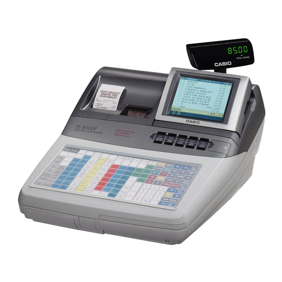
- Page 1 SERVICE MANUAL (without price) ELECTRONIC CASH REGISTER TE-7000S/8000F/8500F (EX-468/568/569) FEB. 2003 TE-7000S TE-8000F TE-8500F INDEX Ver.1 Mar/ 2003...
-
Page 2: Table Of Contents
CONTENTS TE-7000S/8000F/8500F PAGE 1. SPECIFICATIONS..................1 2. CONNECTOR LOCATIONS ................ 4 3. MACHINE INITIALIZATION ................. 5 4. DISASSEMBLY .................... 9 5. CIRCUIT EXPLANATION ................17 6. OPTION INSTALLATION................34 7. IN LINE ....................... 36 8. ON LINE ..................... 39 9. DIAGNOSTIC OPERATION ............... 41 10. -
Page 3: Specifications
1. SPECIFICATIONS 1-1. Electrical specifications 120 V 220 V 230 V 240 V •Power consumption In operation Max. 0.9 A 0.6 A 0.6 A 0.6 A stand-by Max. 0.15 A 0.15 A 0.15 A 0.15 A •Memory protection Back-up battery VL3032/SGB (Vanadium lithium battery) 30 days (25 °C) Back-up period... - Page 4 • Printer head 50 Km (anti-abrasion) • Printer mecanical 6,000,000 hours • Printer cutter 600,000 hours • LCD 36,000 hours • Backlight 36,000 hours 1-5. Drawer List TE-7000S/TE-8000F TE-8500F Type Drawer Name Specification DL-2783 D-19BC-B84M-9* DL-2784 D-19BC-B84SM-9* DL-2424 D-19BC-B55SM-9* DL-2524...
- Page 5 Length 5m Common • PC cable PRL-CB-2 Com1 port only Common • Waterproof cover WT-77 TE-7000S only • Waterproof cover WT-78/79 WT-78: for stroke / WT-79 : for touch TE-8000F only • Waterproof cover WT-62 TE-8500F only • Slip printer...
-
Page 6: Connector Locations
2. CONNECTOR LOCATIONS INLINE1 (AR NET) INLINE ( AT ) INLINE ( AT ) IN TER INAT R R INLINE G und hassis — 4 —... -
Page 7: Machine Initialization
3. Machine Initialization 3-1.How to initialize the terminal Preparation: 1. All peripheral devices and terminals of this cluster should be turned off. 2. Connect all of the peripheral devices (such as printer, display etc.) to terminal. 3. Connect all terminals by in-line. Operation: 4. - Page 8 10. In this field, by pressing <YES> the check cluster No, should be set, if your check tracking system are divided in some Date 01-10-10 Time 12:34 00 clusters. ID Character MC #01 (Enter cluster No. “1”~ “9”, if you use check cluster system.) Check System Master Check cluster ID...
- Page 9 Restore from CF card. 15. Insert the CF card into the slot and select the appropriate file INIT 10-10-01 12:34 000001 and press the <YES> key. Please select one of these options and press the <YES> key. Data Restore 1. PLUPGM1 .004 2.
- Page 10 How to initialize the terminal (add/replace one terminal) Preparation: 1. All peripheral devices and terminals of this cluster should be turned off. 2. Connect all of the peripheral devices (such as printer, display etc.) to this terminal. 3. Connect the added/replaced terminal to inline. Operation: Follow the steps shown on the page 1 to 3.
-
Page 11: Disassembly
4. DISASSEMBLY UPPER COVER 1. Remove the key sheet. (TE-8000F only) 2. Remove the printer cover. 3. Remove the three screws. Remove the upper case by sliding it forward. — 9 —... - Page 12 4. Remove five connectors. (CN17, CN18, CN19, CN21, CN22) Remove the screws and the earth cable. CN19 CN 1 Mode key cover LCD ASS’Y 1. Remove the three screws. Remove the mode key cover. 2. Remove the hinge cover. 3. Remove the three screws and two FPCs. Remove the display case.
- Page 13 1 Remove the screw and the earth cable. 2 Remove the two screws. 3 Remove the LCD ass’y. 5. Remove the two screws. 6. Remove LCD rear case. NOTE: Be careful of the hooks when removing the LCD rear case. Hooks 7.
- Page 14 8. Remove the five screws, four connectors and FPC. Remove the inverter and PCB ass’y. 9. Remove the six screws. 10.Remove the LCD chassis. 11.Remove the LCD unit. — 12 —...
- Page 15 MODE KEY 1. Remove the two screws. Remove the mode key. 2. Remove the two connectors and two FPCs. TE-8000F only 3. Remove the four screws and the earth cable. 4. Remove the contact rubber and PCB ass’y (E468-E6). KEY BOARD ASS’Y 1.
- Page 16 Remove the key board ass’y. Remove the eighteen screws. 2. Remove the two screws. Remove the PCB ass’y (E568-E42). (TE-8000F only) Remove two chassis. Remove the FPC (E ), spacer (E ), and sheet. — 14 —...
- Page 17 BATTERY 1. Remove the connector (CN6). 2. Remove the lithium battery. MAIN PCB ASS’Y 1. Remove the five screws, five connectors and three FPCs. Remove the PCB ass’y (E468-1). — 15 —...
- Page 18 PRINTER 1. Remove the six screws. Remove the printer block. POWER SUPPLY 1. Remove the five screws. Remove the four screws. Remove the power supply. — 16 —...
-
Page 19: Circuit Explanation
5. CIRCUIT EXPLANATION 5-1. BLOCK DIAGRAM — 17 —... - Page 20 5-2. LSI BLOCK DIAGRAM SERIAL RS232C FROM CPU BUS IC19 Backup SDRAM IC18 CPU (SH3) IC33 buffer CF-CARD 1.9V + 3.3V Backup Vrtc only 3.3V or 5V SERIAL buffer PCMCIA 3.3V CONTROLLER IC13 CONTROLLER E-STAMP IC21 buffer ARC-NET IC10 232C Note: 3.3V unless otherwise specified 232C 232C...
- Page 21 5-3. RESET CIRCUIT The reset circuit is as follows. Reset IC 5-4. POWER SUPPLY CIRCUIT The power supply circuit is as follows. VP (DC 25.2V): For the printer control circuit. VCC (DC 5V): For the logic circuit power. V3.3 (DC 3.3V): For the logic circuit power.
- Page 22 5-5. DRAWER I/F CIRCUIT The drawer open circuit is as follows. — 20 —...
- Page 23 5-6. PRINTER CONTROL CIRCUIT The printer control circuit is as follows. — 21 —...
- Page 24 5-7. CPU (IC33) 5-7-1. Pin Assignment STATUS0/PTE [4] CS3/PTC [4] STATUS1/PTE [5] CS2/PTC [3] TCLK/PTE [6] VCCQ IRQOUT/PTE [7] VSSQ VSSQ CKIO RD/WR VCCQ WE3/DQMUU/ICIOWR/PTC [2] TxD0/SCPT [0] WE2/DQMUL/ICIORD/PTC [1] SCK0/SCPT [1] WE1/DQMLU/WE TxD2/SCPT [2] WE0/DQMLL SCK2/SCPT [3] RTS2/SCPT [4] BS/PTC [0] RxD0/SCPT [0] RxD2/SCPT [2]...
- Page 25 5-7-2. Block Diagram CACHE BRIDGE H-UDI SCIF INTC DMAC CPG/WDT I/O port External bus interface Legend: ADC: A/D converter DMAC: Direct memory access controller AUD: Advanced user debugger H-UDI: Hitachi user-debugging interface Interrupt controller BSC: Bus state controller INTC: Memory management unit CACHE: Cache memory MMU:...
- Page 26 5-7-3. Pin Function PIN NO. PIN NAME DESCRIPTION VCC-RTC RTC power supply (1.9 V) XTAL2 On-chip RTC crystal oscillator pin EXTAL2 On-chip RTC crystal oscillator pin Vcc-RTC RTC power supply (0 V) D31/PTB[7] Data bus / input/output port B D30/PTB[6] Data bus / input/output port B D29/PTB[5] Data bus / input/output port B...
- Page 27 PIN NO. PIN NAME DESCRIPTION Address bus VssQ Input/output power supply (0 V) Address bus VccQ Input/output power supply (3.3 V) Address bus Address bus Address bus Address bus Address bus Address bus Address bus Internal power supply (0 V) Address bus Internal power supply (1.9 V) Address bus...
- Page 28 PIN NO. PIN NAME DESCRIPTION TMS/PTG[2] Mode select (H-UDI) / input port G TRST/PTG[3] Reset (H-UDI) / input port G TDO/PTF[5] O/IO Data output (H-UDI) / input/output port F ASEBRKAK/PTF[6] O/IO ASE break acknowledge (H-UDI) / input/output port F ASEMDO ASE mode (H-UDI) Vcc-PLL1 PLL1 power supply (1.9 V)
- Page 29 5-8. I/O CONTROLLER (IC21) 5-8-1. Pin Function Port Convertible terminal Function Circuit Logic Commnet Initial Normal Power Failure INTP0 HCTS CTS from HOST INTP1 R Head up INTP2 J Head up INTP3 DKIN Input DALLAS KEY INTP4 R no paper INTP5 J no paper INTP6...
- Page 30 Port Convertible terminal Function Circuit Logic Commnet Initial Normal Power Failure KI14 KEY input KI15 (MODE input) SW KEY IN SWITCH common input MODE COM MODE KEY common output DW 0 DW 1 WAIT DW 2 ASTB DW 3 RxD2 KEY TYPE 1 KEYboard TYPE 1 TxD2...
- Page 31 5-9. G/A (IC10) 5-9-1. Pin Function PIN NO PIN NAME I / O D E S C R I P T I N PIN NO PIN NAME I / O D E S C R I P T I N VDD VDD VDD VDD ARC DATA (D0)
- Page 32 5-10. LCD CONTROLLER (IC13) 5-10-1. Pin Assignment 60 59 58 57 56 55 54 53 52 51 50 49 48 47 46 45 44 43 42 41 COREVDD FPFRAME FP LINE FP DAT0 FP DAT1 FP DAT2 FP DAT3 FP DAT4 FP DAT5 FP DAT6 S1D137 05...
- Page 33 5-10-3. Pin Function = Input = Output = Bi-Directional (Input/Output) = Power pin = CMOS level input = CMOS level Schmitt input = CMOS output driver, x denotes driver type (see I OL /I OH in Table 6-4: “Output Specifications,” on page 25) = Tri-state CMOS output driver, x denotes driver type (see I OL /I OH in Table 6-4: “Output Specifications,”...
- Page 34 Pin Names Type Pin# Cell RESET# Description State This pin has multiple functions. • For SH-3/SH-4 mode, this pin inputs the write enable signal for the upper data byte (WE1#). • For MC68K #1, this pin inputs the upper data strobe (UDS#). •...
- Page 35 LCD INTERFACE Pin Names Type Pin# Cell RESET# Description State 30, 31, 32, FPDAT[7:0] 33, 34, 35, Panel Data 36, 37 These pins have multiple functions. • Panel Data bits [10:8] for TFT/D-TFD panels. FPDAT 24, 25, 26 Input • General Purpose Input/Output pins GPIO[3:1]. [10:8] These pins should be connected to IO V DD when unused.
-
Page 36: Option Installation
Specification Q'ty Price Note Code 1010 4433 COVER/DALLAS E468 RJE500428-1 This part is attached in the carton box of TE-7000S/8000F/8500F. 1008 6507 DALLAS CABLE ASSY E441328*1 Clerk key kit (CLK-K22) 1007 3068 DAS-02 CABLE SUB ASSY E441319-1 Wire with connector( t = 40mm ) - Page 37 6-2. REMOTE DISPLAY 6-3. HANDY SCNNER 6-4. REMOTE PRINTER / SLIP PRINTER Connect the following peripherals to the COM ports respectively. REMOTE DISPLAY : COM3 HANDY SCANNER : COM2 REMOTE PRINTER/ : COM2, 3, 4 SLIP PRINTER 6-5. DRAWER 6-5-1. CONNECTOR THE DRAWER 1.
-
Page 38: In Line
7. IN LINE There are two types for IN LINE; CATEGORY5A and ARCNET. Note: When the cluster has more than 8 TE-7000S/8000F/8500F terminals, all printer should be local printer. When the cluster has less than or equal to 8 TE-7000S/8000F/8500F terminals, remote printer is allowable. - Page 39 3 ARCNET Cable connection diagram Terminater Terminater 100 ohms Signal 100 ohms Signal Signal FG plate FG plate FG plate (In-line connector) (In-line connector) (In-line connector) [Connection end of ECR] Earth plate In-line connector In-line cable Wrap bent shield wire Black with Copper tape Shield wire...
- Page 40 3 BLOCK DIAGRAM CAT5 UTP Cable CAT5 UTP Cable RS232C (Min 5m) IN (Min 5m) IN Connection INLINE2 (CAT5) OUT INLINE2 (CAT5) IN Terminator Switch Turn on the switch of the units of both first and the last ends. White/Orange 1 1 White/Orange 8, 7, 6, ..2, 1 Orange 2...
-
Page 41: On Line
8-1. Direct connection to PC 1 Connection layout RS-232C KP/M CHK/BM CHK/M KP/BM Slip Slip Slip Using Com1 port 2 PC Cable wiring TE-7000S/8000F/8500F (Com1) Pin No. Signal name Pin No. Pin No. Signal name (DSUB9) (DSUB25) SD/TXD RD/RXD RS/RTS CS/CTS... - Page 42 CD/DCD ER/DTR DR/DSR CI/RI 8-3. PRINTER Connection Three printers can be connected to TE-7000S/8000F/8500F. Com2 ~ Com4 are used for ports. 1 Connection layout Maimum connection number : Max. 3 printer Note:The slip printer can be connected one unit only.
-
Page 43: Diagnostic Operation
9. DIAGNOSTIC OPERATION 9-1. To start the diagnostic operation 1. Power off. 2. While holding down the "Jounal feed" button, turn the power on. 3. Release the button when the main display on. Note: Releace the botton when "INT" appears at the left bottom of the LCD. Normal performance cannot be ensured if the botton was released before "INT"... - Page 44 9-5. Status display [Function] The status of the device which holds the status information is displayed. The displayed device and the status are as follows. D e v i c e Status information D e v i c e Status information (displayed information) (displayed information) Dalllas key...
- Page 45 9-6. Check item The following test can be checked in the diagnostic test. Device to be checked Operation Note Page Test Device : RAM, Flash, Printer, Batch test 1 Date, Time, Buzzer, Drawer Test Device : LCD, Back light, Batch test 2 Rear Display RAM WRITE/READ test n011...
- Page 46 9-7. Operation of each test [ 1 ] Batch test 1 [Function] RAM test, FLASH test, test print, time setting, buzzer test and drawer open test are performed continuously. [Operation] Refer to the page for the details of the following tests. Operation : SUBTOTAL The following tests are performed automatically.
- Page 47 [ 2 ] Batch test 2 [Function] LCD display test, backlight test and REAR DISP tests are performed continuously. [Operation] Refer to the page for the details of the following tests. Operation : SUBTOTAL The following tests are performed automatically. (1) LCD test : LCD test is performed.
- Page 48 [ 3 ] RAM WRITE/READ test [Function] WRITE/READ test for RAM is performed. A counter is displayed for RAM test as follows. [Operation] Operation : SUBTOTAL n: 0 = one time check (can be omitted) not 0 = continuous check (To stop the test, press “Esc” key) [LCD] Displays the address of the error in case the test ended n011...
- Page 49 [ 5 ] FLASH CHECK SUM [Function] CHECK SUM test for FLASH ROM is performed. The area which can be checked is only the code area. The area range depends on the code capacity. [Operation] Operation : SUBTOTAL n: 0 = One time check (can be omitted) not 0 = Continuous check (To stop the test, press “Esc”...
- Page 50 [ 7 ] CF-CARD WRITE/READ test [Function] This test will check the write/read test (connection test) for CF-CARD. Perform the CF-CARD clear test, before start of this test. Note that this test does not ensure the data inside the CF-CARD as well as its performance. [Operation] Operation : SUBTOTAL...
- Page 51 [ 9 ] CF-CARD CLEAR test [Function] This test will check the clear test for CF-CARD. Note that this test does not ensure the data inside the CF-CARD as well as its performance. [Operation] Operation : SUBTOTAL p: designates PCMCIA SLOT 0 = CF 1 = PCMCIA n: 0 = One time check (can be omitted) not 0 = Continuous check (To stop the test, press “Esc”...
- Page 52 [ 11 ] LCD display test [Function] This test will check the LCD. The test ends by the judgment of the operator either by OK or NG only when the one time check is selected. [Operation] The test does not end unless inputting OK or NG key when the one time check is selected. Operation : SUBTOTAL n: 0 = One time check (can be omitted)
- Page 53 [ 12 ] LCD backlight OFF test [Function] This test will check the LCD backlight. The test ends by the judgment of the operator either by OK or NG only. [Operation] The test does not end unless inputting OK or NG key. Operation : SUBTOTAL OK : 1...
- Page 54 [Print] * When the one time check is selected When “OK” key is pressed. NG is printed when “NG” key is pressed. REAR DISP n122 When “OK” key is pressed. NG is printed when “NG” key REAR DISP is pressed. n122 [ 14 ] REMOTE DISPLAY test [Function]...
- Page 55 [ 15 ] External printer print test [Function] This test will check the print test for the RS232C I/F printer. Connect the printer to the COM which is to be tested. [Operation] Operation : x1 x2 x3 SUBTOTAL X1:Print test pattern 0 = A pattern, 1 = B pattern X2:Port selection 1 = COM1, 2 = COM2, 3 = COM3, 4 = COM4...
- Page 56 [ 16 ] Internal printer print test [Function] This test will check the characters in the receipt/journal of the internal printer. [Operation] Operation : SUBTOTAL c: 0 = prints character’ B’ 1 = prints all characters n: 0 = One time check (Can be omitted) not 0 = Continuous check (To stop the test, press “Esc”...
- Page 57 [ 17 ] Internal printer graphic print test [Function] This test will check the graphic patterns in the receipt/journal of the internal printer. [Operation] Operation : P1 P1 P1 P2 P2 P2 SUBTOTAL P1:0 = Graphic patter 1 (change 8 bit into a decimal number and input it) P2:0 = Graphic patter 2 (change 8 bit into a decimal number and input it) n: 0 = One time check (Can be omitted) not 0 = Continuous check (To stop the test, press “Esc”...
- Page 58 [ 18 ] Internal printer dot rate test [Function] This test will check the printing of the receipt/journal according to the following specifications. The printing specification is reflected in 1/2 line and the only specified number of dot lines are printed in all dots from the 1 dot line.
- Page 59 [ 19 ] Internal printer print density test [Function] This will set the print density of the internal printer. This setting is kept until the power is off. The setting will return to the default once the power is turned off.
- Page 60 [ 21 ] RS232C PORT batch test [Function] This is the RS232C port batch test. The loop back test for RS232C port is performed by making the connection shown in the figure. When performing this test, fix loop back connectors to all COM ports. [Operation] Operation : SUBTOTAL...
- Page 61 [ 22 ] ARCNET test [Function] This test will check the counter-communication of ARCNET. Always make the receive ECR in the wait mode first and then send data from the send ECR. Continue the test while the communication is done normally. The counter of the number of receive/send packets to LCD is displayed after the communication normally starts.
- Page 62 [Print] ARCNET rllmmx0a51 rllmmx0a51 * Error print | ARCNET RETRY OVER | Selected retry number was exceeded. | ARCNET BLK ERR | Received does not correspond to the sent Block No. | ARCNET DATA ERR | Received data does not correspond to the sent data. | ARCNET LENG ERR | Received data length does not correspond to the sent data length.
- Page 63 [ 24 ] Time setting [ 25 ] Time display [Function] This sets the time and date. When setting the time, the time and date will be displayed without inputting the fixed value. [Operation] * Date and time setting Operation : x1 x2 x3 x4 x5 x6 SUBTOTAL a: 0: time setting x1/x2: time, x3/x4: minutes, x5/x6: second 1: time setting x1/x2: year, x3/x4: month, x5/x6: day...
- Page 64 [LCD] * When all drawers open one time xn091 When “OK” key is pressed. NG is displayed when “NG” key DRW ALL is pressed. xn091 * The status signal is displayed in the status display position of the LCD. In case of the continuous check and “all drawers open”, the status is displayed after all drawers have opened.
- Page 65 To stop the test, press “Esc” key. [LCD] KEY#mmm [Print] No printing is done in this test. [Location of the key code] TE-7000S TE-8000F 152 153 154 155 157 158 159 160 96 105 114 123 141 150 95 104 113 122...
- Page 66 [ 29 ] OBR test [Function] This is a scanner test. The test enters the wait mode for the scanner input, and waits only for scanner. The test determines the result between OK and NG by comparing the fixed data and the read data. Make sure to connect OBR (HHS-15) to COM 2.
-
Page 67: Error Code List
10. ERROR CODE LIST 10-1. When an error occurs Errors are indicated by an error codes. When this happens, you can usually find out what the problem is as illustrated below. Press C and check the appropriate section of this manual for the operation you want to perform. Prompt message Meaning Action... - Page 68 Prompt message Meaning Action E050 Detail memory Full. Check tracking memory full/near end Finalize and close the check number currently used. E051 CHK/TBL No. is occupied. Attempt is made to use the <NEW Finalize and close the check that CHECK> key to open a new check is currently under thenumber that using a number that is already used you want to use or use a differrent...
- Page 69 Prompt message Meaning Action E075 Negative Balance. Attempted finalization when Register item(s) until the balance Cannot be finalized. balance is less than zero. becomes positive amount. E080 Electronic Journal Full Electronic journal full Reset the electronic journal Please clear E-Journal. memory.
- Page 70 Prompt message Meaning Action E169 Work Hours Exceeded. Overtime work. Follow the prompt message. Please Call Manager. E170 No Shift Reminds in the Schedule. There is no available shift left. You cannot Clock-in. E171 Please Break-out and Retry. Employee attempts to operate Follow the prompt message.
- Page 71 When a fatal error occurs in the OS operation, normal operation cannot be done afterwards. Please carry out the following to stop the ECR operation. When this error occurs, contact Casio Techno to inform of Error NO and Error code. OS Fatal Error!! Error No.1...
-
Page 72: Ic Data
11. IC DATA 1. BA10393F-E2 (IC7, 39) OUT1 –IN1 OUT2 – +IN1 –IN2 – +IN2 2. COM20019ILJP (IC11) nPULSE1 nWR/DIR XTAL2 nRD/nDS XTAL1 A0/nMUX A2/ALE A0/nMUX ADDRESS DECORDING A2/ALE CIRCUITRY 2K 8 ADDITIONAL REGISTERS AD0-AD2, D3-D7 STATUS/ nPULSE1 nINTR COMMAND nPULSE2 REGISTER TX/RX... - Page 73 3. HIN211CA-T (IC1, 2, 3) HIN211E (SOIC, SSOP) TOP VIEW V– C2– C1– 4. L6219DS (IC35, 36) BLOCK DIAGRAM OUT1A Vs (LOAD SUPPLY) OUT2A SENSE1 SENSE2 COMP, INPUT1 COMP, INPUT2 OUT1B OUT2B PHASE1 PHASE2 VREF1 VREF2 Vss (LOGIC SUPPLY) PIN FUNCTIONS PLCC PDIP &...
- Page 74 5. M51957BFP-T1 (IC17) POWER 25uA POWER INPUT OUTPUT INPUT OUTPUT DELAY VALUE 1.25V DELAY VALUE 6. M51957BFP-T1 (IC19) BYTE PIN NAME Function PIN NAME Function RESET N.C. RY/BY RADY/BUSY A1, A0 ~ A20 ADDRESS INPUT WP/ACC RY/BY DQ0 ~ DQ15 DATA BYTE 8 bit/16 bit...
- Page 75 8. SN74AHC1G08DVKR (IC37) 9. SN74AHCT08PWR (IC20) 14 V IN B IN A OUT Y 10. SN74LV00APWR (IC16) 11. SN74LV07APWR (IC32) 14 V 14 V 12. SN74LV08APWR (IC31, 34) 13. SN74LV10APWR (IC15) 14 V 14 V — 73 —...
- Page 76 14. SN74LV14APWR (IC8) (TOP VIEW) FUNCTION TABLE (each inverter) INPUT OUTPUT 15. SN74LV244APWR (IC9)/ SN74LVC244APWR (IC27, 28) 20 V 16. SN74LVC245APWR (IC29, 30) Inputs Output Y T / R Bus B Data to Bus A Bus A Data to Bus B H : High L : Low Don’t care...
- Page 77 17. SN74LVU04APWR (IC22) 18. SN751178NSR (IC14) OUTPUTS INPUT ENABLE H = high level, L = low level, X = irrelevant, Z = high impedance (off) DIFFERENTIAL INPUTS OUTPUT A ± B V ID . 0.2 V ±0.2 V < V ID < 0.2 V V ID 3 ±0.2 V H = high level, L = low level,...
-
Page 78: Pcb Layout
12. PCB LAYOUT MAIN PCB (E468-1 PCB) (TOP VIEW) — 76 —... - Page 79 MAIN PCB (E468-1 PCB) (BOTTOM VIEW) — 77 —...
- Page 80 TACT SW PCB (E468-E6 PCB) (TOP VIEW) (BOTTOM VIEW) — 78 —...
- Page 81 CONNECTOR PCB (E468-CNB1 PCB) (TOP VIEW) (BOTTOM VIEW) ARCNET PCB (E468-ARC PCB) (TOP VIEW) (BOTTOM VIEW) LCD PCB (E468-E2-CL PCB) (TOP VIEW) (BOTTOM VIEW) MENU SW PCB (E568-E42 PCB) TE-8000F only (TOP VIEW) (BOTTOM VIEW) — 79 —...
-
Page 82: Circuit Diagrams
2-10. MAIN PCB CIRCUIT (10/11) ..................91 2-11. MAIN PCB CIRCUIT (11/11) ..................92 3. KEYBOARD PCB CIRCUIT ..................... 93 3-1. TE-7000S (EX-468) ...................... 93 3-2. TE-8000F (EX-568) ...................... 94 3-2. TE-8500F (EX-569) ...................... 95 4. TACT SW PCB CIRCUIT ......................96 2-1. - Page 83 Optional UNIT SIGNAL ONLY Thermal PRN UNIT REAR LED TE-7000S: E468-E4 (STROKE) COM1 MODEM or PC E468-E2-2 E468-E2-2 Receipt Journal TE-8000F: E568-E4 (HYBLID) M-T203A-001 M-T203A-001 M-T203-001 M-T203-001 TE-8500F: E569-E4 (FULL FLAT) Auto Cutter +5V Supply HHS-15 HHS-15 COM2 OPTIONAL Hand Held Scanner...
- Page 84 For software development Model Board No. Name Drawing No. TE-7000S/8000F/8500F (EX-468/568/569) E468-1 CASIO COMPUTER CO.,LTD. BLOCK DIAGRAM [ 1 / 11 ] — 82 —...
- Page 85 For RAC10 SDRAM Model Board No. Name Drawing No. TE-7000S/8000F/8500F E468-1 CASIO COMPUTER CO.,LTD. (EX-468/568/569) BLOCK DIAGRAM [ 2 / 11 ] — 83 —...
- Page 86 For CF-CARD Model Board No. Name Drawing No. TE-7000S/8000F/8500F E468-1 CASIO COMPUTER CO.,LTD. (EX-468/568/569) BLOCK DIAGRAM [ 3 / 11 ] — 84 —...
- Page 87 For PCMCIA (OPTION) Model Board No. Name Drawing No. TE-7000S/8000F/8500F E468-1 CASIO COMPUTER CO.,LTD. (EX-468/568/569) BLOCK DIAGRAM [ 4 / 11 ] — 85 —...
- Page 88 Not used Model Board No. Name Drawing No. TE-7000S/8000F/8500F E468-1 CASIO COMPUTER CO.,LTD. (EX-468/568/569) BLOCK DIAGRAM [ 5 / 11 ] — 86 —...
- Page 89 INLINE1 To E468-ARC Model Board No. Name Drawing No. TE-7000S/8000F/8500F E468-1 CASIO COMPUTER CO.,LTD. (EX-468/568/569) BLOCK DIAGRAM [ 6 / 11 ] — 87 —...
- Page 90 To E468-CNB1 COM4 port Model Board No. Name Drawing No. TE-7000S/8000F/8500F E468-1 CASIO COMPUTER CO.,LTD. (EX-468/568/569) BLOCK DIAGRAM [ 7 / 11 ] — 88 —...
- Page 91 To E468-E6 Model Board No. Name Drawing No. TE-7000S/8000F/8500F E468-1 CASIO COMPUTER CO.,LTD. (EX-468/568/569) BLOCK DIAGRAM [ 8 / 11 ] — 89 —...
- Page 92 Model Board No. Name Drawing No. TE-7000S/8000F/8500F E468-1 CASIO COMPUTER CO.,LTD. (EX-468/568/569) BLOCK DIAGRAM [ 9 / 11 ] — 90 —...
- Page 93 Model Board No. Name Drawing No. TE-7000S/8000F/8500F E468-1 CASIO COMPUTER CO.,LTD. (EX-468/568/569) BLOCK DIAGRAM [ 10 / 11 ] — 91 —...
- Page 94 To E468-E6 Model Board No. Name Drawing No. TE-7000S/8000F/8500F E468-1 CASIO COMPUTER CO.,LTD. (EX-468/568/569) BLOCK DIAGRAM [ 11 / 11 ] — 92 —...
- Page 95 — 93 —...
- Page 96 — 94 —...
- Page 97 — 95 —...
- Page 98 — 96 —...
- Page 99 — 97 —...
- Page 100 — 98 —...
- Page 101 Model Board No. Drawing No. TE-7000S/8000F/8500F CASIO COMPUTER CO .,LTD E468-CNB1 (EX-468/568/569) — 99 —...
- Page 102 Model Board No. Drawing No. TE-7000S/8000F/8500F CASIO COMPUTER CO .,LTD E468-ARC (EX-468/568/569) — 100 —...
- Page 103 Model Board No. Drawing No. TE-7000S/8000F/8500F CASIO COMPUTER CO .,LTD E468-E2-CL (EX-468/568/569) — 101 —...
- Page 104 TE-8000F only Model Board No. Drawing No. TE-8000F (EX-568) CASIO COMPUTER CO .,LTD E568-E42 — 102 —...
-
Page 105: Parts List
2. As for spare parts order and supply, refer to the “GUIDEBOOK for Spare Parts Supply”, published separately. 3. The numbers in item column corespond to the same numbers in drawing. 4. CASIO does not supply the spare parts without parts code. 5. Remarks Q'ty :... - Page 106 TE-7000S LCD Ass'y B C D 69 70 Key Board Ass'y — 104 —...
- Page 107 NOT SUPPLY NOT SUPPLY 93 92 — 105 —...
- Page 108 — 106 —...
- Page 109 — 107 —...
- Page 110 TE-7000S Q'ty Item Code No. Parts Name Specification Other Countries Price USA/ Europe Australia Plug Type Code Canada Europe UK USA 1. MAIN PCB BLOCK 1 10104430 PCB ASSY/E468-1 RJE500408*1 N IC33 10100136 LSI HD6417706F133 1 CK N IC21 10111217 LSI...
- Page 111 Q'ty Item Code No. Parts Name Specification Other Countries Price USA/ Europe Australia Plug Type Code Canada Europe UK USA R145 RESISTOR/CHIP RC1608-3001-F-T R147,185 RESISTOR/CHIP RC1608-4702-F-T RESISTOR/CHIP RC1608-5602-F-T RESISTOR/CHIP RC315-15R0-F-T N RM19,20 26601173 RESISTOR/CHIP NETWORK RAC1608-0004DJT 2 AA RM1,2,5,9,10,18, 26601156 RESISTOR/CHIP NETWORK RAC1608-1034DJT 38 AA 29-33,44,51-53,57,...
- Page 112 Q'ty Item Code No. Parts Name Specification Other Countries Price USA/ Europe Australia Plug Type Code Canada Europe UK USA FU2,3 30008079 FUSE/CHIP 430.500 2 AD CN15 10074027 CONNECTOR AXN380130P 1 BE 77401603 CONNECTOR B2B-PH-SM3-TB 1 AC CN25 35019394 CONNECTOR B2B-ZR-SM3-TF 1 AB CN11-14...
- Page 113 Q'ty Item Code No. Parts Name Specification Other Countries Price USA/ Europe Australia Plug Type Code Canada Europe UK USA SCREW S-PASEMA-4X5ZC SCREW S-PASEMA-3X6ZC 10115091 FG CABLE SUB ASSY RJE500484*1 1 AB 16 10113436 HOLDER/HINGE E468 RJE500441-1 1 AD 10114087 SHEET/BLIND E468 RJE500443-1 3.
- Page 114 Q'ty Item Code No. Parts Name Specification Other Countries Price USA/ Europe Australia Plug Type Code Canada Europe UK USA PLATE/S E240526-43 PLATE/S E240526-44 PLATE/S E240526-57 PLATE/S E240526-58 PLATE/S E240526-59 PLATE/S E240526-60 PLATE/S E240526-61 RECEIPT FEED PLATE/S E240526-62 JOURNAL FEED PLATE/S E240526-63 RECEIPT...
- Page 115 Q'ty Item Code No. Parts Name Specification Other Countries Price USA/ Europe Australia Plug Type Code Canada Europe UK USA SCREW S-PAMA-3X6B 61 10114130 COVER/MODE KEY RJE500440-2 1 BD 10115091 FG CABLE SUB ASSY RJE500484*1 1 AB 10115092 FG CABLE SUB ASSY RJE500484*2 1 AC 10115541 SHEET/BLIND...
- Page 116 Q'ty Item Code No. Parts Name Specification Other Countries Price USA/ Europe Australia Plug Type Code Canada Europe UK USA 94 94870776 SCREW 1073844 2 AB 95 94870777 CUTTER/FIXED 1231681 1 BK 96 94870778 SPRING 1231999 1 AA 97 10114233 CHASSIS/PR L RJE500466-1 1 AR 98 10114234 CHASSIS/PR R...
- Page 117 TE-8000F LCD Ass'y B C D 73 74 Key Board Ass'y — 115 —...
- Page 118 Assy NOT SUPPLY NOT SUPPLY 98 97 — 116 —...
- Page 119 SH-KIT10 (Sales item) WT-79 39 40 WT-79 SPRING X 2 — 117 —...
- Page 120 — 118 —...
- Page 121 Q'ty Item Code No. Parts Name Specification Other Countries Price R USA/ Code Europe Australia Plug Type Canada Europe 1. MAIN PCB BLOCK 1,(49) 10118742 PCB ASSY SET/E468-1 (2pcs) RJE500408*2 N IC33 10100136 LSI HD6417706F133 N IC21 10111217 LSI UPD784215AGC8028EU IC10 10073986 LSI UPD65945GJ-P16-JEU...
- Page 122 Q'ty Item Code No. Parts Name Specification Other Countries Price R USA/ Code Europe Australia Plug Type Canada Europe R145 RESISTOR/CHIP RC1608-3001-F-T R147,185 RESISTOR/CHIP RC1608-4702-F-T RESISTOR/CHIP RC1608-5602-F-T RESISTOR/CHIP RC315-15R0-F-T N RM19,20 26601173 RESISTOR/CHIP NETWORK RAC1608-0004DJT RM1,2,5,9,10,18, 26601156 RESISTOR/CHIP NETWORK RAC1608-1034DJT 29-33,44,51-53,57, 58,60,61,64,66,68, 70,75-82,90,92-94,...
- Page 123 Q'ty Item Code No. Parts Name Specification Other Countries Price R USA/ Code Europe Australia Plug Type Canada Europe FU2,3 30008079 FUSE/CHIP 430.500 CN15 10074027 CONNECTOR AXN380130P 77401603 CONNECTOR B2B-PH-SM3-TB CN25 35019394 CONNECTOR B2B-ZR-SM3-TF CN11-14 35021809 CONNECTOR B3B-PH-SM3-TB CN22 35021340 CONNECTOR B4B-ZR-SM3-TF 35018645 CONNECTOR B5B-PH-SM3-TB...
- Page 124 Q'ty Item Code No. Parts Name Specification Other Countries Price R USA/ Code Europe Australia Plug Type Canada Europe SCREW S-PASEMA-4X5ZC SCREW S-PASEMA-3X6ZC 10115091 FG CABLE SUB ASSY RJE500484*1 10113436 HOLDER/HINGE E468 RJE500441-1 10114087 SHEET/BLIND E468 RJE500443-1 3. Customer Display block 10104422 CASE/RDP E468 RJE500324-1 10104421 PANEL/RDP E468...
- Page 125 Q'ty Item Code No. Parts Name Specification Other Countries Price R USA/ Code Europe Australia Plug Type Canada Europe PLATE/S E240526-112 PLATE/S E240526-113 PAGE DOWN PLATE/S E240526-114 PAGE UP PLATE/S E240526-115 HOME PLATE/S E240526-118 -> MENU SHIFT PLATE/S E240526-125 PLATE/S E240526-126 ESC/SKIP PLATE/L...
- Page 126 Q'ty Item Code No. Parts Name Specification Other Countries Price R USA/ Code Europe Australia Plug Type Canada Europe 10085156 DRAWER CABLE SUB ASSY E440737*1 10104437 COVER/CF E468 RJE500311-1 10104444 CABLE/FFC JOINER BE468 E440657-11 10104429 CHASSIS/POWER SUPPLY RJE500404-1 10104440 ARC CABLE SUB ASSY RJE500386*1 10104439 COVER/POWER SWITCH RJE500340-1...
- Page 127 Q'ty Item Code No. Parts Name Specification Other Countries Price R USA/ Code Europe Australia Plug Type Canada Europe RM1-5 27753288 RESISTOR/CHIP NETWORK MNR14E0ABJ103 C2,4,6 CAPACITOR/CHIP GRM1882C1H101JA01D C1,3,5 CAPACITOR/CHIP GRM188B11E104KA01D 28073647 CAPACITOR/ELECTROLYTIC RV2-16V101MS-R D1-15 10009218 DIODE/CHIP 1SS400TE61 Q1-5 22501603 TRANSISTOR/CHIP 2SB1182TLQR 35405184 CONNECTOR HFW10S-2STE1...
- Page 128 TE-8500F LCD Ass'y B C D 52 53 Key Board Ass'y — 126 —...
- Page 129 Assy NOT SUPPLY NOT SUPPLY — 127 —...
- Page 130 WF62 (Sales item) — 128 —...
- Page 131 — 129 —...
- Page 132 Q'ty Item Code No. Parts Name Specification Price Rank USA/ Code Canada 1. MAIN PCB BLOCK 10104430 PCB ASSY/E468-1 RJE500408*1 N IC33 10100136 HD6417706F133 N IC21 10111217 UPD784215AGC8028EU IC10 10073986 UPD65945GJ-P16-JEU N IC19 10103458 MBM29DL324BE90TNAA N IC18 10100310 MD56V62160E-10TAB0 N IC13 10100311 S1D13705F00A100 IC11...
- Page 133 Q'ty Item Code No. Parts Name Specification Price Rank USA/ Code Canada R145 RESISTOR/CHIP RC1608-3001-F-T R147,185 RESISTOR/CHIP RC1608-4702-F-T RESISTOR/CHIP RC1608-5602-F-T RESISTOR/CHIP RC315-15R0-F-T N RM19,20 26601173 RESISTOR/CHIP NETWORK RAC1608-0004DJT RM1,2,5,9,10,18, 26601156 RESISTOR/CHIP NETWORK RAC1608-1034DJT 29-33,44,51-53,57, 58,60,61,64,66,68, 70,75-82,90,92-94, 96,110,111 N RM59,102-104 26601160 RESISTOR/CHIP NETWORK RAC1608-1044DJT N RM8,13-17,25-28,...
- Page 134 Q'ty Item Code No. Parts Name Specification Price Rank USA/ Code Canada CN15 10074027 CONNECTOR AXN380130P 77401603 CONNECTOR B2B-PH-SM3-TB CN25 35019394 CONNECTOR B2B-ZR-SM3-TF CN11-14 35021809 CONNECTOR B3B-PH-SM3-TB CN22 35021340 CONNECTOR B4B-ZR-SM3-TF 35018645 CONNECTOR B5B-PH-SM3-TB CN17 35017546 CONNECTOR B5B-ZR-SM3-TF N CN18 35019765 CONNECTOR B12B-ZR-SM3-TF...
- Page 135 Q'ty Item Code No. Parts Name Specification Price Rank USA/ Code Canada SCREW S-PASEMA-3X6ZC FG CABLE SUB ASSY 10115091 RJE500484*1 10113436 HOLDER/HINGE E468 RJE500441-1 10114087 SHEET/BLIND E468 RJE500443-1 3. Customer Display block CASE/RDP E468 10104422 RJE500324-1 10104421 PANEL/RDP E468 RJE500323-1 43081401 PCB/E445A-E2-2 E340800-1...
- Page 136 Q'ty Item Code No. Parts Name Specification Price Rank USA/ Code Canada 7. Lower case block 10104438 CASE/LOWER E468 RJE500338-1 10104428 MAIN CHASSIS E468 RJE500304-1 10104436 SUB CHASSIS E468 RJE500305-1 10054340 INLINE CABLE SUB ASSY E440720*3 10085156 DRAWER CABLE SUB ASSY E440737*1 10104437 COVER/CF E468...
- Page 137 Q'ty Item Code No. Parts Name Specification Price Rank USA/ Code Canada R1,2,7 RESISTOR/CHIP MCR03EZHJ000 R11-13,15-21, RESISTOR/CHIP MCR03EZHJ101 24-30 R3,5,8,10,22 RESISTOR/CHIP MCR03EZHJ103 R4,6,9,14,23 RESISTOR/CHIP MCR03EZHJ471 RM1-5 27753288 RESISTOR/CHIP NETWORK MNR14E0ABJ103 C2,4,6 CAPACITOR/CHIP GRM1882C1H101JA01D C1,3,5 CAPACITOR/CHIP GRM188B11E104KA01D 28073647 CAPACITOR/ELECTROLYTIC RV2-16V101MS-R D1-15 10009218 DIODE/CHIP 1SS400TE61...
- Page 138 13. DRAWER (DL-2424) — 136 —...
- Page 139 DL-2424 (M type) Item Code No. Parts Name Specification Qt'y Price Rank CASE/MAIN ZD65310 NOT SUPPLY 19068961 STOPPER ZD48117 94870790 DRAWER SUB ASSY ZD65320 94870791 FRONT PANEL ZD65321 19026842 ROLLER/DERLIN DR-19B 94870792 PLATE/COIN PARTITION ZD63953 94870793 EARTH/BRUSH ZD48124 19068964 PLATE/BOTTOM ZD48130 94870794 RUBBER/STOPPER ZD48132...
- Page 140 14. DRAWER (DL-2524) — 138 —...
- Page 141 DL-2524 (M type) Item Code No. Parts Name Specification Qt'y Price Rank CASE/MAIN ZD65310 NOT SUPPLY 19068961 STOPPER ZD48117 94870790 DRAWER SUB ASSY ZD65320 94870791 FRONT PANEL ZD65321 19026842 ROLLER/DERLIN DR-19B 94870792 PLATE/COIN PARTITION ZD63953 94870793 EARTH/BRUSH ZD48124 19068964 PLATE/BOTTOM ZD48130 94870794 RUBBER/STOPPER ZD48132...
- Page 142 15. DRAWER (DL-2783) — 140 —...
- Page 143 DL-2783 (M type) Item Code No. Parts Name Specification Qt'y Price Rank CASE/MAIN ZD65310 NOT SUPPLY 19068961 STOPPER ZD48117 94870790 DRAWER SUB ASSY ZD65320 94870791 FRONT PANEL ZD65321 19026842 ROLLER/DERLIN DR-19B 94870792 PLATE/COIN PARTITION ZD63953 94870793 EARTH/BRUSH ZD48124 19068964 PLATE/BOTTOM ZD48130 94870794 RUBBER/STOPPER ZD48132...
- Page 144 16. DRAWER (DL-2784) — 142 —...
- Page 145 DL-2784 (M type) Item Code No. Parts Name Specification Qt'y Price Rank CASE/MAIN ZD65310 NOT SUPPLY 19068961 STOPPER ZD48117 94870790 DRAWER SUB ASSY ZD65320 94870791 FRONT PANEL ZD65321 19026842 ROLLER/DERLIN DR-19B 94870792 PLATE/COIN PARTITION ZD63953 94870793 EARTH/BRUSH ZD48124 19068964 PLATE/BOTTOM ZD48130 94870794 RUBBER/STOPPER ZD48132...
- Page 146 17. DRAWER (DL-3616) — 144 —...
- Page 147 DL-3616 (L type) USA, Canada Item Code No. Parts name Specification Q'ty Price Code RANK 19077272 LOCK ASSY ZD00290-0 19060672 NUT M4XP0.7 94870383 LABEL DL-3616 19079613 WIRE/FG ZD31670 19070223 CONNECTOR 1625-03PI 19027112 GROMET 19027076 SPRING ZD01370B 19026829 RUBBER/DAMPER K2320 19070234 SCREW/TAPPING M4X16 19026842 ROLLER/DERLIN DR-19B...
- Page 148 18. DRAWER (DL-3617) — 146 —...
- Page 149 DL-3617 (L type) Saudi-Arabia Item Code No. Parts name Specification Q'ty Price Code RANK 19077935 LOCK ASSY ZD00280-0 19060672 NUT M4XP0.7 94870384 LABEL DL-3617 19079613 WIRE/FG ZD31670 19070223 CONNECTOR 1625-03PI 19027112 GROMET 19027076 SPRING ZD01370B 19026829 RUBBER/DAMPER K2320 19070234 SCREW/TAPPING M4X16 19026842 ROLLER/DERLIN DR-19B...
- Page 150 Ver.1 : • DIAGNOTIC OPERATION Correction of Operation code (P55, P60) • Correction of erratum (P60) CASIO TECHNO CO.,LTD. Overseas Service Division 6-2, Hon-machi 1-Chome Shibuya-ku, Tokyo 151-8543, Japan...