Juniper MX2020 Quick Start Manual
3d universal edge router
Hide thumbs
Also See for MX2020:
- Hardware manual (454 pages) ,
- Hardware manual (630 pages) ,
- Hardware manual (800 pages)
Table of Contents
Advertisement
Quick Links
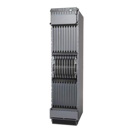
MX2020 3D Universal Edge Router
Quick Start
January 2015
Part Number: 530-053305
Revision 01
Contents
Copyright © 2015, Juniper Networks, Inc.
This document describes how to install the Juniper Networks
Edge Router.
MX2020 Quick Start Description . . . . . . . . . . . . . . . . . . . . . . . . . . . . . . . . . . . . . . . . 3
Step 1: Prepare the Site for Installation . . . . . . . . . . . . . . . . . . . . . . . . . . . . . . . . . . . 4
Rack-Mounting Requirements . . . . . . . . . . . . . . . . . . . . . . . . . . . . . . . . . . . . . . 4
Moving Requirements and Guidelines Using a Router Transport Kit . . . . . . . . 6
Step 2: Install the Mounting Hardware . . . . . . . . . . . . . . . . . . . . . . . . . . . . . . . . . . . 11
Step 3: Install the Router . . . . . . . . . . . . . . . . . . . . . . . . . . . . . . . . . . . . . . . . . . . . . 13
Unpack the Router . . . . . . . . . . . . . . . . . . . . . . . . . . . . . . . . . . . . . . . . . . . . . . . 13
Remove Components . . . . . . . . . . . . . . . . . . . . . . . . . . . . . . . . . . . . . . . . . . . . 17
Install the Router Using a Pallet Jack with Attachment . . . . . . . . . . . . . . . . . 22
Install the Pallet Jack Attachment . . . . . . . . . . . . . . . . . . . . . . . . . . . . . . 23
Install the Router Using a Router Transport Kit . . . . . . . . . . . . . . . . . . . . . . . . 28
Unpack the Router Transport Kit . . . . . . . . . . . . . . . . . . . . . . . . . . . . . . . 28
Install the Router Transport Kit onto the Router . . . . . . . . . . . . . . . . . . . 30
Use the Transport Kit to Install the Router in the Rack . . . . . . . . . . . . . . . 32
Step 4: Connect the Grounding Cable . . . . . . . . . . . . . . . . . . . . . . . . . . . . . . . . . . . 43
Step 5: Reinstall Components . . . . . . . . . . . . . . . . . . . . . . . . . . . . . . . . . . . . . . . . . 44
Step 6: Connect External Devices and Line Card Cables . . . . . . . . . . . . . . . . . . . . 45
Connect to a Network for Out-of-Band Management . . . . . . . . . . . . . . . . . . 45
Connect a Management Console . . . . . . . . . . . . . . . . . . . . . . . . . . . . . . . . . . . 45
Connect the Line Card Cables . . . . . . . . . . . . . . . . . . . . . . . . . . . . . . . . . . . . . 45
Step 7: Connect Power Cables . . . . . . . . . . . . . . . . . . . . . . . . . . . . . . . . . . . . . . . . . 47
Connect AC Power Supply Modules . . . . . . . . . . . . . . . . . . . . . . . . . . . . . . . . . 55
Connect Power to a DC Power Distribution Module . . . . . . . . . . . . . . . . . . . . 58
®
MX2020 3D Universal
1
Advertisement
Chapters
Table of Contents

Related Manuals for Juniper MX2020


Summary of Contents for Juniper MX2020
-
Page 1: Table Of Contents
MX2020 Quick Start Description ........ - Page 2 MX2020 3D Universal Edge Router Quick Start Connect DC Power Supply Modules ....... . 60 Step 8: Perform Initial Software Configuration .
-
Page 3: Mx2020 Quick Start Description
Adapter cards provide housing to MPCs. The MPCs attach to the adapter cards, which in turn connect to the backplane. Up to two MICs can be installed in each MPC. Fully populated, the MX2020 router supports up to 40 MICs. -
Page 4: Step 1: Prepare The Site For Installation
Rack-Mounting Requirements on page 4 Moving Requirements and Guidelines Using a Router Transport Kit on page 6 Tools Required to Unpack and Prepare the MX2020 Router for Installation on page 9 Rack-Mounting Requirements You can install the router in a four-post rack or cabinet. - Page 5 Rack-Mounting Requirements NOTE: For a complete list of individual line card and component weights and measurements, see the MX2020 3D Universal Edge Router Hardware Guide at http://www.juniper.net/techpubs/ For the cooling system to function properly, the airflow around the chassis must be unrestricted.
-
Page 6: Moving Requirements And Guidelines Using A Router Transport Kit
24 in (61cm) to 30 in (76.2 cm) Moving Requirements and Guidelines Using a Router Transport Kit The MX2020 requires a minimum 42 in. (106.7 cm) diameter of space to turn the chassis on the router transport kit (see Figure 2 on page... - Page 7 (106.7 cm) The weight of the router transport kit is 138.5 lb (63 kg). The maximum recommended height the MX2020 should be lifted from the floor using the router transport kit is 1.5 in. (3.8 cm). Viewed from the side, the router with the router transport kit installed measures 78.75 in.
- Page 8 MX2020 3D Universal Edge Router Quick Start Figure 3: Measurements of the Router Transport Kit Installed on the MX2020 (Side View) 78.75 in (200.0 cm) 23.40 in (59.4 cm) 36.20 in (91.95 cm) Viewed from the front, the router with the router transport kit installed measures 30.78 in.
-
Page 9: Tools Required To Unpack And Prepare The Mx2020 Router For Installation
Tools Required to Unpack and Prepare the MX2020 Router for Installation Figure 4: Measurements of the Router Transport Kit Installed on the MX2020 (Front View) 19.0 in (48.26 cm) 30.78 in (78.2 cm) Tools Required to Unpack and Prepare the MX2020 Router for Installation... - Page 10 MX2020 3D Universal Edge Router Quick Start Electrostatic discharge wrist strap Antistatic mat NOTE: We recommend that you install the MX2020 by using a pallet jack with attachment or a router transport kit. Copyright © 2015, Juniper Networks, Inc.
-
Page 11: Step 2: Install The Mounting Hardware
Slide the four-post rack mounting shelf between the rack rails, resting the bottom of the shelf on the rack supports. The four-post rack mounting shelf installs on the rear rack rails, extending toward the front of the rack, as specified in the MX2020 3D Universal Edge Router Hardware Guide, for large shelf installation. - Page 12 30 in (76.2 cm) NOTE: There must be a minimum of 45-U unobstructed front-to-back usable rack space when installing the MX2020 router into a four-post rack or cabinet. NOTE: If you are installing the MX2020 router into a network cabinet, make sure that no hardware, device, rack, or cabinet component obstructs the 45-U rack space from access during installation.
-
Page 13: Step 3: Install The Router
48.0 in. (121.9 cm) deep (see Figure 6 on page 14). See Table 1 on page 4 for MX2020 shipping weight specifications. NOTE: The total weight of the shipping crate with router and accessories varies depending on your configuration. Copyright © 2015, Juniper Networks, Inc. - Page 14 Depending on your configuration, the MX2020 might be shipped with additional components already installed. NOTE: The MX2020 can be ordered with extended EMI covers and extended cable managers. Before removing the router from the shipping crate, you must remove all components (see “Remove Components”...
- Page 15 NOTE: If you ordered a router transport kit, the shipping crate door is used as a ramp to guide the MX2020 out of the crate. Using a two-person team, slide the remainder of the shipping crate off the pallet (see Figure 7 on page 16).
- Page 16 MX2020 3D Universal Edge Router Quick Start Figure 7: Unpacking the MX2020 LINE Remove the foam covering the top of the router. Remove the pallet jack attachment, if ordered. See “Unpack the Router Transport Kit” on page 28 for instructions on how to unpack and install the router transport kit.
-
Page 17: Remove Components
Remove Components The router might have field replacement units (FRUs) installed. Remove these FRUs from the MX2020 router before installing the router into a rack or cabinet (see Figure 8 on page Figure 9 on page... - Page 18 MICs (bottom) Figure 9: Components to Remove from the Rear of an AC-Powered MX2020 Router Remove field replacement units (FRUs) from the rear of the MX2020 router before you install the router. See Table 3 on page 19 for information about MX2020 router components.
- Page 19 AC PSM 0 through 8 PSM air filter – AC PDM—Three-phase PDM0/Input0 delta or wye Fan tray air filter – Lower fan trays (two) Fan tray 0 and fan tray 1 (behind access door) Copyright © 2015, Juniper Networks, Inc.
- Page 20 MX2020 3D Universal Edge Router Quick Start Figure 10: Components to Remove from the Rear of a DC-Powered MX2020 Router Remove field replacement units (FRUs) from the rear of the MX2020 router before you install the router. See Table 4 on page 20 for information about MX2020 router components.
- Page 21 Remove Components Table 4: Components to Remove from the Rear of a DC-Powered MX2020 Router (continued) Component Component Description Slots Number of FRUs PSM air filter – DC PDM PDM0/Input0 DC cable – manager–(standard or extended) Fan tray air filter –...
-
Page 22: Install The Router Using A Pallet Jack With Attachment
MX2020 3D Universal Edge Router Quick Start Press and hold the latch while simultaneously pulling the fan tray out approximately 1 to 3 in. Place one hand under the fan tray for support, while pulling the fan tray completely out of the router. -
Page 23: Install The Pallet Jack Attachment
Tighten the torque fasteners by using a 9/16-in. (14 mm) socket wrench to secure the brackets on the pallet jack attachment to the pallet jack (see Figure 13 on page 23). Figure 13: Installing MX2020 Pallet Jack Attachment Copyright © 2015, Juniper Networks, Inc. -
Page 24: Use A Pallet Jack With Attachment To Install The Router In The Rack
Ensure that the rack or cabinet is in its permanent location and is secured to the building. Ensure that the installation site allows adequate clearance for both airflow and maintenance. For details, see the MX2020 3D Universal Edge Router Hardware Guide. - Page 25 Use a Pallet Jack with Attachment to Install the Router in the Rack Figure 14: Loading the MX2020 Router onto the Pallet Jack M X2 ONLI OFFL Attach the shipping brackets to the pallet jack attachment by using the existing bracket screws.
- Page 26 Using the pallet jack, position the router in front of the rack or cabinet, centering it in front of the mounting shelf. NOTE: If you are installing the MX2020 router into a network cabinet, make sure that no hardware, device, rack, or cabinet component obstructs the 45-U rack space from access during installation.
- Page 27 (depending on your type of installation). The shelf ensures that the holes in the front-mounting flanges of the chassis align with the holes in the rack rails (see Figure 16 on page 27). Figure 16: Loading the MX2020 Router into the Rack M X2 ONLI OFFL NOTE: There must be a minimum of 45 U of usable rack space when installing the MX2020 router into a 45-U rack.
-
Page 28: Install The Router Using A Router Transport Kit
MX2020 3D Universal Edge Router Quick Start Insert sixteen mounting screws (eight on each side) into the mounting holes to secure the router to the rack. Visually inspect the alignment of the router. If the router is installed properly in the rack, all the mounting screws on one side of the rack should be aligned with the mounting screws on the opposite side, and the router should be level. - Page 29 Remove the two wing nuts that secure the wooden brace to the shipping crate platform, and set them aside. Align the crate door with the shipping crate platform, and secure the door to the platform using the attached velcro straps (see Figure 19 on page 30). Copyright © 2015, Juniper Networks, Inc.
-
Page 30: Install The Router Transport Kit Onto The Router
MX2020 3D Universal Edge Router Quick Start Figure 19: Router Transport Kit Shipping Crate Door Crate door/ramp Remove the router transport kit from the shipping container. Remove the vapor corrosion inhibitor (VCI) packs attached to the pallet, being careful not to break the VCI packs open. - Page 31 (see Figure 21 on page 32). Using a number 3 Phillips screwdriver, tighten the captive screws to secure the router transport mounting plate and wheel assembly to the chassis. Copyright © 2015, Juniper Networks, Inc.
-
Page 32: Use The Transport Kit To Install The Router In The Rack
Figure 21 on page 32). Using a number 3 Phillips screwdriver, tighten the captive screws to secure the router transport mounting plate and wheel assembly to the chassis. Figure 21: Installing the Router Transport Kit onto the MX2020 Router MAST ONLIN OFFLI Use the Transport Kit to Install the Router in the Rack Because of the router's size and weight—up to 1515 lb (687.2 kg) depending on the... - Page 33 Use the Transport Kit to Install the Router in the Rack To install the MX2020 by using a router transport kit: Ensure that the rack is in its permanent location and is secured to the building. Ensure that the installation site allows adequate clearance for router transport kit turn ratios, airflow, and maintenance.
- Page 34 MX2020 3D Universal Edge Router Quick Start NOTE: The router transport kit is equipped with four T-shaped levels on top of each of the four router transport mounting brackets. Make sure that the bubbles within the T-shaped levels are between the lines, indicating that the chassis is level.
- Page 35 Figure 23: Securing the Router Transport Platform Install the winch strap plate to the rear of the router by using the four captive screws, and tighten the screws (see Figure 24 on page 36). Copyright © 2015, Juniper Networks, Inc.
- Page 36 MX2020 3D Universal Edge Router Quick Start Figure 24: Installing Winch Strap Plate Using a four-person team, transport the router to the rack installation location and center it in front of the mounting shelf. NOTE: A minimum of 38 in. (96.5 cm) of clearance is required to roll the chassis sideways.
- Page 37 Make sure the bubbles within the T-shaped levels are between the lines, indicating the router is level. Adjust the four leveling mounts on the router transport platform until all four leveling mounts rest firmly on the ground (see Figure 26 on page 38). Copyright © 2015, Juniper Networks, Inc.
- Page 38 MX2020 3D Universal Edge Router Quick Start Figure 26: Aligning the MX2020 Router with Rack Mounting Shelf Unlock the four toggle latches that secure the router transport platform to the router transport mounting plate and wheel assembly. Lift the wheels up by turning the handles counterclockwise so that the weight of the router is on the router transport platform.
- Page 39 Use the Transport Kit to Install the Router in the Rack Figure 27: Removing Router Transport Mounting Plate and Wheel Assembly Attach the winch strap to the winch strap plate at the rear of the router (see Figure 28 on page 40). Copyright © 2015, Juniper Networks, Inc.
- Page 40 MX2020 3D Universal Edge Router Quick Start Figure 28: Attaching Winch Strap to Winch Strap Plate Attach a 1-1/8 in. (28.57 mm) socket wrench to the winch mechanism and turn clockwise to start pulling the chassis into the rack (see Figure 29 on page 41).
- Page 41 Use the Transport Kit to Install the Router in the Rack Figure 29: Pulling the MX2020 into the Rack NOTE: A four-person team is needed to carefully guide the router into the rack while operating the winch. Copyright © 2015, Juniper Networks, Inc.
- Page 42 MX2020 3D Universal Edge Router Quick Start NOTE: If the router is not pulled all the way into the rack by the winch mechanism, grasp the handles on the shipping covers and carefully slide the router onto the mounting shelf until the front-mounting flanges contact the rack rails.
-
Page 43: Step 4: Connect The Grounding Cable
ESD points on the chassis. For more information about ESD, see the MX2020 3D Universal Edge Router Hardware Guide. Place the grounding cable lug over the grounding points. The upper pair is sized for UNC 1/4-20 bolts, and the lower pair is sized for M6 bolts. -
Page 44: Step 5: Reinstall Components
MX2020 3D Universal Edge Router Quick Start Step 5: Reinstall Components To reinstall the components in the router: Take each component out of its electrostatic bag, and identify the slot on the component where it will be connected. NOTE: Remove the shipping covers before installing router components. -
Page 45: Step 6: Connect External Devices And Line Card Cables
Have ready a length of the type of cable used by the MPCs or MICs. For cable specifications, see the MX Series Interface Module Reference If the cable connector port is covered by a rubber safety plug, remove the plug. Copyright © 2015, Juniper Networks, Inc. - Page 46 MX2020 3D Universal Edge Router Quick Start WARNING: Do not look directly into a fiber-optic transceiver or into the ends of fiber-optic cables. Fiber-optic transceivers and fiber-optic cables connected to a transceiver emit laser light that can damage your eyes.
-
Page 47: Step 7: Connect Power Cables
Depending on your configuration, your router uses either AC or DC power distribution modules (PDMs). Perform the appropriate procedures for each PDM in your router. For more information about PDMs, see the MX2020 3D Universal Edge Router Hardware Guide. CAUTION: Do not mix AC and DC power modules within the same router. - Page 48 PDM before the PDM can be removed from the chassis. The MX2020 chassis is not sensitive to phase rotation sequence—either clockwise or counterclockwise will operate correctly. To connect wires to the terminal block that serves six PSMs: a.
- Page 49 The three-phase delta AC PDM terminal blocks will be flipped depending on which slot the PDM gets plugged into. CAUTION: Wire label configuration is for Juniper Networks supplied cable only. If you are using your own cable, make sure that you use the proper connections.
- Page 50 MX2020 3D Universal Edge Router Quick Start NOTE: Three-phase delta AC wire assembly kits can be purchased from Juniper Networks. Table 5: Supported Three-Phase Delta AC Wire Gauge Wire Gauge Description 4 x 6-AWG or equivalent 4 conductor wires, each wire is 6-AWG...
-
Page 51: Connect Power To A Three-Phase Wye Ac Power Distribution Module
Loosen the input terminal or grounding point screw, insert each wire into the grounding point or input terminal, and tighten the screw (see Table 7 on page 54 for approved AC wire gauge). Copyright © 2015, Juniper Networks, Inc. - Page 52 PDM before the PDM can be removed from the chassis. The MX2020 chassis is not sensitive to phase rotation sequence—either clockwise or counterclockwise will operate correctly. To connect wires to the terminal block that serves six PSMs: a.
- Page 53 PDM gets plugged into. CAUTION: Wire label configuration is for Juniper Networks supplied cable only. If using your own cable, make sure you use the proper connections. To connect wires to the terminal block that serves three PSMs: a.
- Page 54 MX2020 3D Universal Edge Router Quick Start NOTE: Three-phase wye AC wire assembly kits can be purchased from Juniper Networks. Table 7: Supported Three-Phase Wye AC Wire Gauge Wire Gauge Description 5 x 10-AWG or equivalent 5 conductor wires, each wire is 10-AWG...
-
Page 55: Connect Ac Power Supply Modules
The DIP switches are used only to indicate presence of a feed. If both feeds are present, power is always drawn from feed . Only if feed fails will power be drawn from feed Copyright © 2015, Juniper Networks, Inc. -
Page 56: See Table
NOTE: The MX2020 router configured for three-phase wye AC input power must use only three-phase wye AC PDMs and AC PSMs. The MX2020 router configured for three-phase delta AC input power must use three-phase delta AC PDMs and AC PSMs. AC and DC PSMs or PDMs must not be mixed within a single router. - Page 57 PSMs in slots , and , where required. Figure 39: MX2020 AC Power Supply Module Front View NOTE: Each PSM slot not occupied by an AC PSM must be covered by a PSM blank panel. Copyright © 2015, Juniper Networks, Inc.
-
Page 58: Connect Power To A Dc Power Distribution Module
Attach an electrostatic discharge (ESD) grounding strap to your bare wrist, and connect the strap to one of the ESD points on the chassis. For more information about ESD, see the MX2020 3D Universal Edge Router Hardware Guide. NOTE: If the DC PSMs are installed in the router, make sure that the power switch is turned to the off ( ) position. - Page 59 MX2020 3D Universal Edge Router Hardware Guide. Connect each DC power cable to the appropriate external DC power source. NOTE: For information about connecting to external DC power sources, see the MX2020 3D Universal Edge Router Hardware Guide. Copyright © 2015, Juniper Networks, Inc.
-
Page 60: Connect Dc Power Supply Modules
MX2020 3D Universal Edge Router Quick Start Switch on the external circuit breakers to provide voltage to the DC power source cable leads. NOTE: Each PDM must be connected to a dedicated 60 A 80 A circuit breaker for the DC power source. The PDM has a switch to accommodate DC circuit breaker amperage. - Page 61 Tighten the two captive screws to secure the PSM to the chassis. NOTE: The MX2020 router configured for DC input power must use only DC PDMs and DC PSMs. AC and DC PSMs or PDMs must not be mixed within a single router.
- Page 62 DC input is detected but voltage is out of range. – DC input to the PSM is not present. Repeat Steps through for installing PSMs in slots , and , where required. Figure 42: MX2020 DC Power Supply Module Front View Copyright © 2015, Juniper Networks, Inc.
- Page 63 Connect DC Power Supply Modules NOTE: Each PSM slot not occupied by a DC PSM must be covered by a PSM blank panel. Copyright © 2015, Juniper Networks, Inc.
-
Page 64: Step 8: Perform Initial Software Configuration
Junos OS configuration guides. Check the LEDs on the craft interface to verify the hardware status after reinstalling or powering on the MX2020 router. For a list of system status verification commands, see the MX2020 3D Universal Edge Router Hardware Guide at http://www.juniper.net/techpubs/... -
Page 65: Configure System Attributes
Ethernet port. Access to the management Ethernet port is limited to the local subnet. To access the management Ethernet port from a remote subnet, you must add a static route to that subnet within the routing table. Copyright © 2015, Juniper Networks, Inc. -
Page 66: Commit The Configuration
MX2020 3D Universal Edge Router Quick Start [edit] root# set routing-options static route remote-subnet next-hop destination-IP retain no-readvertise Configure the telnet service at the [edit system services] hierarchy level. [edit] root#set system services telnet Commit the Configuration Display the configuration to verify that it is correct. -
Page 67: Safety Warnings
Only trained and qualified personnel should install or replace the router. Perform only the procedures described in this Quick Start or in the MX2020 3D Universal Edge Router Hardware Guide. Other services should be performed by authorized service personnel only. - Page 68 MX2020 3D Universal Edge Router Quick Start Always remove all components before moving the router. The empty router weighs 330 lb (149.68 kg). When installing the router, do not use a ramp inclined more than 10 degrees. Measure the shipping container to make sure there is adequate clearance through doorways and passages to accommodate the dimensions.
-
Page 69: Compliance Statements For Nebs
The battery return connection is to be treated as an isolated DC return (i.e. DC-I), as defined in GR-1089-CORE. For Juniper systems with AC power supplies, an external surge protective device (SPD) must be used at the AC power source. -
Page 70: Israel
MX2020 3D Universal Edge Router Quick Start Israel Translation from Hebrew—Warning: This product is Class A. In residential environments, the product may cause radio interference, and in such a situation, the user may be required to take adequate measures. Japan Translation from Japanese—This is a Class A product. -
Page 71: Junos Os Documentation And Release Notes
7 days a week, 365 days a year. Self-Help Online Tools and Resources For quick and easy problem resolution, Juniper Networks has designed an online self-service portal called the Customer Support Center (CSC) that provides you with the following features: Find CSC offerings: http://www.juniper.net/customers/support/... -
Page 72: Opening A Case With Jtac
Juniper Networks, Junos, Steel-Belted Radius, NetScreen, and ScreenOS are registered trademarks of Juniper Networks, Inc. in the United States and other countries. The Juniper Networks Logo, the Junos logo, and JunosE are trademarks of Juniper Networks, Inc. All other trademarks, service marks, registered trademarks, or registered service marks are the property of their respective owners.