Table of Contents
Advertisement
Quick Links
Operation, Repair, Parts
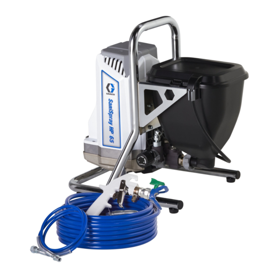
SaniSpray HP
Portable Hopper Sprayer
For portable spraying of water-based disinfectants approved for spray application only.
Not for applying architectural paints and coatings. Not approved for use in explosive
atmospheres or hazardous (classified) locations. For professional use only.
Important Safety Instructions
Read all warnings and instructions in this manual, related manuals, and on the unit
including the power cord. Be familiar with the controls and the proper usage of the
equipment. Save these instructions.
Important Medical Information
Read the medical alert card provided with the sprayer. It contains injection injury
treatment information for a doctor. Keep it with you when operating the equipment.
WARNING
CHEMICAL HAZARD
To prevent serious injury:
•
Follow all directions and
requirements on disinfectant
label. It is a violation of Federal
law to use an EPA-approved
disinfectant in a manner
inconsistent with its labeling.
•
Flush after each use. Never
store disinfectant in
equipment.
•
Use only with appropriate
personal protective
equipment.
Use only genuine Graco replacement parts.
The use of non-Graco replacement parts may void warranty.
65
™
844-241-9499
3A7653A
EN
Advertisement
Table of Contents

Related Manuals for Graco SaniSpray HP 65


Summary of Contents for Graco SaniSpray HP 65
- Page 1 • Flush after each use. Never store disinfectant in equipment. • Use only with appropriate personal protective equipment. 844-241-9499 Use only genuine Graco replacement parts. The use of non-Graco replacement parts may void warranty.
-
Page 2: Table Of Contents
Graco Information ........ -
Page 3: Important User Information
Important User Information Important User Information Before using your You must also read and disinfectant sprayer, follow the information on read this manual for the disinfectant container complete instructions label and ask for a Safety on proper use and Data Sheet (SDS) from safety warnings. -
Page 4: Warnings
Check hoses and parts for signs of damage. Replace any damaged hoses or parts. • This system is capable of producing 1000 psi (69 bar, 6.9 MPa). Use Graco parts or accessories that are rated a minimum of 1000 psi (69 bar, 6.9MPa). - Page 5 Use Graco conductive or grounded high-pressure airless sprayer hoses. •...
- Page 6 Warnings WARNING ELECTRIC SHOCK HAZARD This equipment must be grounded. Improper grounding, setup, or usage of the system can cause electric shock. • Turn off and disconnect power cord before servicing equipment. • Connect only to grounded electrical outlets. • Use only 3-wire extension cords.
- Page 7 Warnings WARNING GROUNDING This product must be grounded. In the event of an electrical short circuit, grounding reduces the risk of electric shock by providing an escape wire for the electric current. This product is equipped with a cord having a grounding wire with an appropriate grounding plug. The plug must be plugged into an outlet that is properly installed and grounded in accordance with all local codes and ordinances.
-
Page 8: Know Your Sprayer
Know Your Sprayer Know Your Sprayer Fluid Outlet Fitting (Airless Hose con- Prime/Spray Valve nection) PushPrime Button Airless Hose Pressure Control Knob Airless Whip Hose ON/OFF Switch Power Cord Hopper Easy Access Door Drain Tube (with diffuser) Pump Removal Tool Flex Plus Airless Spray Gun Inlet Valve Removal Tool Spray Tip... -
Page 9: Grounding
Grounding Grounding The equipment must be grounded to reduce the risk of static sparking and electric shock. An electric or static spark can cause fumes to ignite or explode. An improper ground can cause electric shock. A good ground provides an escape wire for the electric current. -
Page 10: Setup
When unpacking sprayer for the first time or after long term storage, perform Setup procedure. Connect 1/4” Graco Airless Hose to Fluid Outlet Fitting (remove red storage plug from fitting if present). Use wrenches to tighten securely. -
Page 11: Start Up
Start Up Start Up Engage the Trigger Lock. Always engage the Trigger Lock when sprayer is stopped to prevent the Spray Gun from being triggered accidentally. Pressure Relief Procedure Follow the Pressure Relief Procedure whenever you see this symbol. Turn Pressure Control Knob to the lowest setting. - Page 12 Start Up Put Drain Tube in a pail and turn If you suspect the Spray Tip or hose is Prime/Spray Valve horizontal to PRIME clogged or that pressure has not been position to relieve pressure. fully relieved: VERY SLOWLY loosen the Spray Tip Guard retaining nut or the Airless Hose end coupling to relieve pressure gradually.
-
Page 13: Flushing A New Sprayer
Start Up Flushing a New Sprayer Pour approximately two quarts of warm soapy water into the Hopper. This sprayer arrives from the factory with a Turn Prime/Spray Valve horizontal to small amount of test fluid in the system. It is PRIME position. -
Page 14: Fill Pump
Start Up Fill Spray Gun and Airless Turn ON/OFF Switch to ON position. Hose Hold Spray Gun against waste bucket. Point Spray Gun into waste bucket. Disengage Trigger Lock. Pull and hold Spray Gun trigger. Turn Prime/Spray Valve up to Rotate Pressure Control Knob clockwise SPRAY position. - Page 15 Start Up Clip Drain Tube to Hopper. NOTE: When motor stops, sprayer is ready to spray disinfectant. If motor continues to run, sprayer is not properly primed, repeat Fill Pump and Fill Spray Gun and Airless Hose, page 14. 3A7653A...
-
Page 16: How To Spray
How to Spray How to Spray Use Spray Tip (A) to align gasket and seal (B) in the Spray Tip Guard (C). Use only disinfectants approved for spray application. Fumes from disinfectants with alcohol active ingredients, or from other flammable disinfectants, can explode or ignite. -
Page 17: Starting Your Spray And Adjusting Pressure
How to Spray Starting Your Spray and Release Trigger. Engage Trigger Lock. Rotate Spray Tip to UNCLOG position. Adjusting Pressure Disengage Trigger Lock. Trigger Spray Gun in waste bucket to clear clog. Always refer to the disinfectant manufacturer’s UNCLOG recommendations for an acceptable spray of disinfectant. -
Page 18: Cleanup
Cleanup Cleanup Cleaning the sprayer is required after each Remove Drain Tube from Hopper, wipe use to remove any disinfectants and residues excess disinfectant from outside of Drain from the sprayer. It will also help ensure a Tube and inside of Hopper. trouble free start up the next time the sprayer is used. -
Page 19: Clean The Gun
Cleanup Allow water to flow out of drain tube and 13. Stop triggering Spray Gun. Engage the into waste bucket until approximately 1/3 Trigger Lock. of the water is emptied from the Hopper. 10. Turn ON/OFF Switch to OFF position. NOTE: Step 11 is for removing disinfectant from the Airless Hose. -
Page 20: Storage
Storage Storage With proper storage, the sprayer will be ready to use the next time it is needed. NOTICE Disinfectant left in sprayer will damage the sprayer. To avoid damage, always completely flush with warm soapy water after every use. See Cleanup, page 18. Do not store sprayer with disinfectant in it. -
Page 21: Quick Reference
Storage Quick Reference Page 8 Name Description • Prime/Spray Valve In PRIME position directs fluid to Drain Tube. • In SPRAY position directs pressurized fluid to Airless Hose. • Automatically relieves system pressure in overpressure situations. PushPrime Button Taps the inlet ball when pushed to loosen it. Pressure Control Knob Increases (clockwise) and decreases (counterclockwise) fluid pressure in pump, Airless... -
Page 22: Maintenance
Maintenance Maintenance Routine maintenance is important to ensure proper operation of your sprayer. Activity Interval Inspect/clean Fluid Inlet strainer. Daily or each time you spray Inspect motor shroud openings for blockage. Daily or each time you spray Pump Removal NOTICE The Hopper must be removed before pump Protect the internal drive parts of this can be removed. -
Page 23: Pump Installation
Maintenance Slide pump assembly off the mounting Move pump displacement rod up or pins. down until cap is level with the opening in the yoke. ti27037a Swing Easy Access Door pump door closed while pushing the entire door towards the inlet end of the pump. Pump Installation Slide pump assembly onto the mounting pins. -
Page 24: Inlet Valve Removal
Recycling and Disposal Inlet Valve Removal NOTICE An integrated tool is included in the frame to Do not lose the ball and spring inside the inlet remove the inlet valve assembly from the valve assembly. It may fall out when the inlet pump. -
Page 25: Troubleshooting
Troubleshooting Troubleshooting Solutions at the beginning of each problem listed are the most common, Start at the beginning and continue down the list to find a solution. 844-241-9499 Disconnect power and follow Pressure Relief Procedure, page 11, before checking or repairing. Problem Cause Solution... - Page 26 Troubleshooting Problem Cause Solution Sprayer runs, but pump does Inlet valve check ball is stuck. Press PushPrime Button to not prime or loses prime while dislodge the ball allowing in use (pump cycles but does pump to prime properly. not pump material or build Prime/Spray Valve is in Turn Prime/Spray Valve down pressure).
- Page 27 Troubleshooting Problem Cause Solution Cannot trigger Spray Gun. Spray Trigger Lock is Rotate Trigger Lock to engaged. disengage trigger lock. See page 12. Material is coming out of Pressure control is worn. Replace Pump Assembly. See pressure control. Parts, page 28. Material leaks down outside of Pump packings are worn.
-
Page 28: Parts
Parts Parts 25R792 Hopper Sprayer Parts List - 25R792 Hopper Sprayer Ref. Part Description Qty. Ref. Part Description Qty. 19Y883 LABEL, warning, cord 25R920 KIT, pump 222385 CARD, medical alert, 25R921 KIT, motor, drive EN, ES, FR (not shown) 25R922 KIT, enclosure 19Y894 LABEL, warning, cord ... -
Page 29: Wiring Diagrams
Wiring Diagrams Wiring Diagrams 110/120V ti27233a 3A7653A... -
Page 30: Technical Specifications
Technical Specifications Technical Specifications SaniSpray HP 65 Portable Hopper Sprayer Metric Sprayer Maximum fluid working pressure 1000 psi 69 bar, 6.9 MPa Maximum Delivery 0.5 gpm 1.9 lpm Maximum Tip Size 0.021 in. 0.053 mm Fluid Outlet npsm 1/4 in. -
Page 31: Graco Warranty
Graco warrants all equipment referenced in this document which is manufactured by Graco and bearing its name to be free of defects in material and workmanship on the date of sale by an authorized Graco distributor to the original purchaser for use. Graco will, for a period of ninety (90) days from the date of sale, send repair parts to the owner for equipment determined by Graco to be defective. -
Page 32: Graco Information
All written and visual data contained in this document reflects the latest product information available at the time of publication. Graco reserves the right to make changes at any time without notice. Original instructions. This manual contains English. MM 3A7653...