Invacare Pronto M41 Series User Manual
With surestep
Hide thumbs
Also See for Pronto M41 Series:
- Service manual (112 pages) ,
- User manual (96 pages) ,
- Owner's manual (72 pages)

Related Manuals for Invacare Pronto M41 Series


Summary of Contents for Invacare Pronto M41 Series
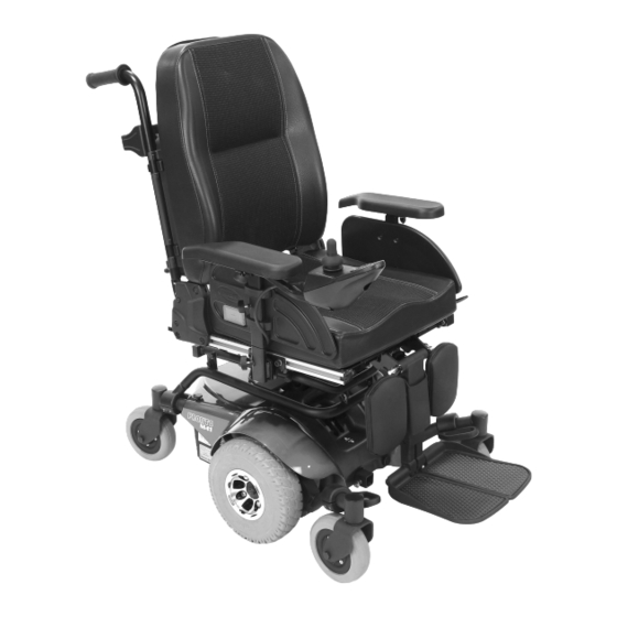
- Page 1 Invacare® Pronto™ M41 Series with SureStep® en Power Wheelchair User Manual This manual MUST be given to the user of the product. BEFORE using this product, read this manual and save for future reference.
- Page 2 All rights reserved. Republication, duplication or modification in whole or in part is prohibited without prior written permission from Invacare. Trademarks are identified by ™ and ®. All trademarks are owned by or licensed to Invacare Corporation or its subsidiaries unless otherwise noted.
-
Page 3: Table Of Contents
5 Setup ......... . . 28 Contents 5.1 General setup information . - Page 4 5.5.13 Adjusting the width of the backrest (Modulite seat 5.14.1 Swivelling the legrest outward and/or removing ..58 unit)........43 5.14.2 Setting the angle .
- Page 5 5.18 Powered elevating legrests (ADE legrests)... . 74 7.2.3 How to charge the batteries....87 5.18.1 Swivelling the legrest outward and/or removing .
- Page 6 10.2 Disposal ........105 11 Technical Data ........106 11.1 Technical specifications .
-
Page 7: General
This mobility device was designed for persons whose ability product safety notices and product recalls, contact your to walk is impaired, but who are still in terms of their Invacare representative. See addresses at the end of this eyesight and physically and mentally able to operate an document. -
Page 8: Indications
• obstacle climbing (15 mm) • brake failure • lighting (no light option) You should immediately contact an authorized Invacare • drive range (15 km) provider if the usability of your mobility device is restricted • ground clearance (10 mm) -
Page 9: Warranty Information
1.10 Limitation of liability • damage to the legrest hangers (e.g. missing or torn heel straps) Invacare accepts no liability for damage arising from: • damage to the postural belt • damage to the joystick (joystick cannot be moved into •... -
Page 10: Safety
Invacare® Pronto™ M41 Series with SureStep® 2 Safety WARNING! Risk of injury if the mobility device is driven when ability to operate a vehicle is impaired by 2.1 General safety notes medication or alcohol – Never drive the mobility device under the DANGER! influence of medication or alcohol. - Page 11 Safety WARNING! WARNING! Risk of injury if the mobility device is switched Risk of falling out of the mobility device off while driving, for example by pressing the – Do not slide forward on the seat, do not lean On/Off Button or disconnecting a cable, due to forward between your knees, do not lean it coming to an abrupt, sharp stop backwards out over the top of the backrest, for...
-
Page 12: Safety Information On The Electrical System
Invacare for this purpose. Have all electrical the batteries. Be sure at all times to adopt the installations done by your authorized Invacare correct lifting posture and ask for assistance provider. - Page 13 Safety WARNING! WARNING! Risk of death, serious injury or damage when Risk of death, serious injury, or damage carrying along oxygen systems Corroded electrical components due to water or Textiles and other materials that normally would liquid exposure can result in death, serious injury, not burn are easily ignited and burn with great or damage.
-
Page 14: Safety Information On Electromagnetic Interference
Invacare® Pronto™ M41 Series with SureStep® WARNING! Risk of damage to the mobility device Risk of death or serious injury A failure in the electric system can lead to Failure to observe these warnings can cause an unusual behavior such as continuous light, no electrical short resulting in death, serious injury, light, or noises from the magnetic brakes. -
Page 15: Safety Information On Driving And Freewheel Mode
Safety 2.4 Safety information on driving and freewheel WARNING! mode Risk of malfunction due to electromagnetic interference DANGER! – Do not switch on or operate portable Risk of death, serious injury, or damage transceivers or communication devices (such as Malfunctioning joystick could cause radio transceivers or cellular phones) when the unintended/erratic movement resulting in vehicle is switched on. - Page 16 Invacare® Pronto™ M41 Series with SureStep® WARNING! WARNING! Risk of injury if the mobility device tips over Risk of injury if the mobility device tips over – Inclines and declines can only be travelled (continued) up to the maximum safe slope (refer to 11 –...
- Page 17 Safety WARNING! WARNING! Risk of breaking down in adverse weather Risk of injury conditions, i.e. extreme cold, in an isolated area If your mobility device has been fitted with – If you are a user with severely limited mobility, elevating legrests, there is a risk of personal we advise that in the case of adverse weather injury and damage to the mobility device if you conditions DO NOT attempt a journey without...
-
Page 18: Safety Information With Regard To Care And Maintenance
Invacare® Pronto™ M41 Series with SureStep® 2.5 Safety information with regard to care and 2.6 Safety information regarding changes and maintenance modifications to the mobility device DANGER! WARNING! Risk of death, serious injury, or damage Risk of serious injury or damage... - Page 19 Invacare. Electrical and electronic components which have – In this case, the company that adds or replaces not been approved by Invacare for use with this the components or accessories is responsible mobility device can cause fire hazards and lead for the conformity assessment/CE marking or to electromagnetic damage.
-
Page 20: Safety Information On Wheelchairs With A Lifter
Invacare® Pronto™ M41 Series with SureStep® Important information about maintenance work CAUTION! tools Risk of injury if the wheelchair tips over – Some maintenance work which is described in – Never exceed the maximum permissible load this manual and can be carried out by the user (see chapter 11 Technical Data, page106 ). -
Page 21: The Position Of The Labels On The Product
Safety 2.8 The position of the labels on the product CAUTION! Damage to wheelchair caused by one-sided loading on lifter pillar – One-sided loading occurs if the seat is raised and/or tilted. Always return your seat backrest to the upright position and the seat tilting to the horizontal position before ascending slopes. - Page 22 Invacare® Pronto™ M41 Series with SureStep® Identification of the The mobility device is position of the coupling a class A product. It lever for driving and push is intended mainly for operation. internal use and not necessarily capable of For details see below.
- Page 23 Safety Explanation of symbols on labels This product complies with Directive 93/42/EEC concerning medical devices. Read the user manual. This symbol The launch date of this product is stated appears on different labels and positions. in the CE declaration of conformity. This product has been supplied from an Indicates a hazardous situation.
-
Page 24: Components
3 Components Information regarding operation of the lifter at temperatures of less than 0 °C • Invacare mobility devices are fitted with safety 3.1 Key features mechanisms that prevent capacity overload of the electronic components. At operating temperatures below freezing point this can, in particular, lead to the lifter actuator being shut down after approx. - Page 25 Risk of tipping, if the speed limiter sensors fail when the lifter is raised – If you find that the speed reduction function is not working when the lifter is raised, do not drive with the lifter raised and immediately contact an authorized Invacare provider. 1553378-G...
-
Page 26: Accessories
Invacare® Pronto™ M41 Series with SureStep® Belt can be adjusted on both sides. This means that the 4 Accessories buckle can be centrally positioned. Belt with plastic buckle, adjustable both sides 4.1 Posture belts A posture belt is an option which can either be fixed to the mobility device ex-works or can be retrofitted by your specialist provider. - Page 27 If the belt is only fastened with a bolted connection, ensure that the connection has not loosened or come undone. You can find more information about maintenance work on belts in the service manual, which is available from Invacare. 1553378-G...
-
Page 28: Setup
Off and re-enter set-up specifications. – The mobility device is fitted with an individual, Contact Invacare, if mobility device still does multiply adjustable seating system including not perform to correct specifications. adjustable legrests, armrests, a headrest or other options. -
Page 29: Adjustment Possibility For Remote
Setup Initial setup should always be done by a healthcare CAUTION! professional. Adjustment by the user is only Risk of the remote being pushed backwards recommended after they have been given during an accidental collision with an obstacle, appropriate guidance by the healthcare professional. such as a doorframe or table, and the joystick being jammed against the armpad if the position of the remote is adjusted and all screws are not... -
Page 30: Adjusting The Remote For The Length Of The User's
Invacare® Pronto™ M41 Series with SureStep® 5.2.1 Adjusting the remote for the length of the user's 5.2.3 Swivelling the remote to the side 1. Loosen wing bolt A. 2. Shift the remote forwards or backwards to the desired distance. If your mobility device is fitted with a swing-away remote 3. -
Page 31: Adjusting Position Of Joysticks And Remote
Setup 5.3.1 Adjusting position of joysticks and remote Switch joystick Linkage joystick and RJM/RJM-LF remote Risk of damage to screws If you tighten screws to an improper torque, they might either come loose or get damaged. – Tighten the screws to a torque of 3 Nm ± 10 %. •... -
Page 32: Adjusting Height Of Linkage Switch
Invacare® Pronto™ M41 Series with SureStep® 1. Loosen ball joint A. 2. Position linkage. 3. Tighten ball joint. 5.3.2 Adjusting Height of Linkage Switch Risk of damage to clamping lever If you tighten clamping lever to an improper torque, it might either come loose or get damaged. -
Page 33: Adjustment Possibilities For The Standard Seat Unit
Setup 5.4 Adjustment possibilities for the standard seat unit 5.4.1 Adjusting the height of the armrests Depending on the side, the screw is accessible from the front or the rear. 1. Loosen wing screw A. 2. Adjust armrest to desired height. •... -
Page 34: Adjusting The Backrest
Invacare® Pronto™ M41 Series with SureStep® 5.4.3 Adjusting the backrest 5.4.4 Adjusting the tension adjustable backrest upholstery CAUTION! Adjusting the seat tilt or the backrest angle changes the geometry of the mobility device and directly influences its dynamic stability! – For details regarding dynamic stability,... -
Page 35: Adjustment Options For The Modulite Seat Unit
Setup 5.5 Adjustment options for the Modulite seat unit 5.5.1 Adjusting the height of the armrests Depending on the side, the screw is accessible from the front or the rear. 1. Loosen wing screw A. 2. Adjust armrest to desired height. •... -
Page 36: Adjusting The Position Of The Armrest In Depth
Invacare® Pronto™ M41 Series with SureStep® 1. Loosen the screws A and move the armrest lengthwise. 2. Tighten the screws. 5.5.4 Adjusting the height (flip-up armrest) 1. Loosen screw A. 2. Adjust armrest to required position. 3. Retighten the screw. -
Page 37: Adjusting The Height (Following Armrest)
Setup 5.5.5 Adjusting the height (following armrest) Tools: • 5 mm Allen key • 13 mm wrench 1. To make the armrest easier to move, release the screw A with the Allen key. 2. To make the armrest more difficult to move, tighten the screw A with the Allen key. -
Page 38: Adjusting The Position Of The Arm Pad Of The Flip-Up Armrest
Invacare® Pronto™ M41 Series with SureStep® 1. Loosen screws A. Do not remove them. 2. Adjust arm pad to desired angle. 3. Tighten screws. 5.5.8 Adjusting the position of the arm pad of the flip-up armrest • 5 mm Allen key Position the armrest horizontally. - Page 39 Setup Removing hip support 1. Loosen screw A. Do not remove it. 1. Pull lever A upwards. 2. Adjust hip support to desired position. 2. Remove hip support from holder. 3. Tighten screw. Inserting hip support Adjusting width of hip support 1.
- Page 40 Invacare® Pronto™ M41 Series with SureStep® 1. Loosen screws A. 2. Adjust hip support to desired width. You can adjust the width only smaller than the seat width but not wider. 3. Tighten screws. Adjusting angle of hip support Tools •...
- Page 41 Setup Loosen the two screws A. Remove upper screw and friction cap A. 2. Remove small friction link B. Remove hip pad bracket from mounting slot via cut-out 3. Insert hip pad bracket in other mounting slot. Remove hip pad with bracket, turn upside down and 4.
-
Page 42: Adjusting The Seat Width
The service instructions can be ordered from the service instructions for this mobility device. The service Invacare. However, they contain instructions for instructions can be ordered from Invacare. However, they specially trained technicians and describe operations contain instructions for specially trained service technicians that are not intended for the end user. -
Page 43: Adjusting The Height Of The Backrest
5 mm Allen key replacement description, see the service instructions for this mobility device. The service instructions can be ordered from Invacare. However, they contain instructions for specially trained service technicians and describe operations that are not intended for the end user. -
Page 44: Adjusting The Backrest Angle
Invacare® Pronto™ M41 Series with SureStep® CAUTION! Risk of falling out of the wheelchair When adjusting the backrest, it might move backward unexpectedly and you might fall out of the wheelchair. – Do not rest against the backrest while adjusting If the backrest is fitted with knobs instead of Allen screws, you do not need tools. -
Page 45: The Captain's Seat
Setup 5.6 The Captain’s seat 1. On both sides, loosen and remove the upper backrest screw A. 5.6.1 Adjusting the armrest width 2. Set the required backrest angle in 3.8° steps. Use scale B on the backrest for this purpose. Ensure that you set the same angle on both sides. -
Page 46: Adjusting The Armrest Height
Invacare® Pronto™ M41 Series with SureStep® 1. Remove the lock knob A that secures the armrest C to the arm frame assembly B. 2. Adjust the armrest to one of five positions D. 3. Reinstall the lock knob that secures the armrest to the arm frame assembly and tighten securely. -
Page 47: Adjusting The Seat Angle
– A headrest must be installed. The headrest 2. Let go of the release handle to lock the backrest in optionally supplied for this mobility device by position. Invacare is perfectly suitable for use during transport. – The headrest must be adjusted to the user's ear height. -
Page 48: Adjusting Position Of Rea Headrest Or Neckrest
Invacare® Pronto™ M41 Series with SureStep® 1. Loosen the screws A , B or the clamping lever C. 2. Adjust the headrest or neckrest to the required position. 3. Retighten screws and clamping lever. 4. Loosen the Allen screw D. -
Page 49: Adjusting Elan Headrest
• An optional shim plate is available. It may be Invacare is perfectly suitable for use during installed between the clamp assembly and the transport. back pan to provide additional spacing/clearance –... - Page 50 Invacare® Pronto™ M41 Series with SureStep® 1. Using hardware provided, align and install headrest clamp assembly into existing mounting holes in backrest pan A. Upper multi-angle • 360° rotation 2. Install headrest pad (not shown) to headrest rod using rotational pivot •...
-
Page 51: Center-Mounted Footboard
Setup 5.10 Center-mounted footboard Adjusting depth and angle The headrest can be further adjusted for depth and angle WARNING! via the articulating hardware. After any adjustments, repair or service and before use, make sure that all attaching • 4 mm Allen key hardware is tightened securely - otherwise injury •... -
Page 52: Adjusting The Footboard Assembly Angle
Invacare® Pronto™ M41 Series with SureStep® 1. Position the footboard assembly onto the wheelchair WARNING! frame so that the mounting hole in the wheelchair Make sure the detent balls of the quick-release frame D aligns with the desired mounting hole in the pin are fully released beyond the outer edge footboard assembly. -
Page 53: Adjusting The Footboard Assembly Depth
Setup 3. Thread the jam nut and washer inward until it is flush 5.10.4 Adjusting the footboard assembly height with the footboard bracket. 4. Securely tighten the jam nut and washer to secure the mounting screw in place. 5.10.3 Adjusting the footboard assembly depth WARNING! Make sure the detent balls of the quick-release pin are fully released beyond the outer edge... -
Page 54: Setting The Angle Of The Leg Rest
Invacare® Pronto™ M41 Series with SureStep® 1. Hold the leg rest securely. 2. Pull the lever (1). 3. Push the leg rest into the required position. Remove removable axle (1). 5.11.3 Setting the length of the leg rest • 3/16'' (4.8 mm) Allen key You can adjust the length of the leg rests independently of one another. -
Page 55: Setting The Angle Of The Footplate
5.12.1 Setting the length of the legrest • 5/32'' (4 mm) Allen key If needed, the legrest can be pre-set to 83° or 97° instead of 90°. Contact your Invacare provider. • 4 mm Allen key • 10 mm open-ended wrench You can adjust the length of the legrests independently of one another. -
Page 56: Setting The Angle Of The Footplate
Invacare® Pronto™ M41 Series with SureStep® 3. Loosen nuts B at the side of legrest. It may be necessary to remove the nuts and move them from one slot to the other. 4. Set desired length. 5. Retighten nuts. 6. Refit the calf pads and cover and retighten screws. -
Page 57: Standard 80° Footrest
Setup The small release lever is to be found in the upper part Calf pad adjustment — sample configurations of the legrest (1). When the legrest is released it can be swivelled inward or outward to facilitate access and also be removed completely. -
Page 58: Manually Height-Adjustable Legrest
Invacare® Pronto™ M41 Series with SureStep® 1. Press unlocking knob (1) and remove legrests upwards. 1. Loosen the screw (1) using the Allen key, but do not remove completely. 5.14.2 Setting the angle 2. Set the legrest to the desired length. -
Page 59: Adjusting The Length Of The Legrest
Setup 1. Press the unlocking lever (1) down. Adjust the legrest to the required angle. 1. Loosen bolt (1) with the Allen key. 2. Release the unlocking lever. The legrest engages. 2. Adjust to required length. 5.14.3 Adjusting the length of the legrest 3. -
Page 60: Adjusting The Height Of The Calf Pad
Invacare® Pronto™ M41 Series with SureStep® 1. Loosen the hand screw (1). 2. Adjust to required position. 3. Retighten the wing nuts. 5.15 Vari-F footrest 5.15.1 Swivelling the footrest/legrest outward and/or removing The small unlocking button is located on the upper section of the footrest/legrest. -
Page 61: Setting The Angle
Setup 5.15.2 Setting the angle CAUTION! Risk of injury due to incorrect adjustment of the footrests and legrests – Before and during every journey it is imperative to ensure that the legrests contact neither the caster wheels nor the ground. •... - Page 62 Invacare® Pronto™ M41 Series with SureStep® Fig. 5-3 The end position of the footrest is determined by means of a rubber stop (1). Fig. 5-5 Use the Allen key to loosen the screw (1) and swivel the footrest upward in order to access the rubber stop.
-
Page 63: Adjusting The Length Of The Legrest
Setup 5.15.4 Adjusting the length of the legrest CAUTION! Risk of injury due to incorrect adjustment of the footrests and legrests – Before and during every journey it is imperative to ensure that the legrests contact neither the caster wheels nor the ground. •... -
Page 64: Vari-A Legrests
Invacare® Pronto™ M41 Series with SureStep® 5.16 Vari-A legrests 5.16.2 Setting the angle 5.16.1 Swivelling the footrest/legrest outward and/or CAUTION! removing Risk of injury due to incorrect adjustment of the footrests and legrests The small unlocking button is located on the upper section of –... -
Page 65: Setting The End Stop Of The Legrest
Setup Set the desired angle. Loosen the locking knob (1) counter-clockwise at least one turn. Turn the knob clockwise to tighten it. 5.16.3 Setting the end stop of the legrest • 10 mm wrench Hit the knob to release the locking mechanism. 1553378-G... - Page 66 Invacare® Pronto™ M41 Series with SureStep® The end position of the legrest is determined by means of a rubber stop (1). Loosen the locking knob (1) counter-clockwise at least one turn. The rubber stop can be screwed in or out A or pushed up or down B.
- Page 67 Setup Move the rubber stop to the desired position. 8. Re-tighten the counternut. Swivel the legrest upward in order to access the rubber stop. Use the wrench to loosen the counternut (1). Move the legrest to the desired position. 10. Re-tighten the locking knob. 1553378-G...
-
Page 68: Adjusting The Length Of The Legrest
Invacare® Pronto™ M41 Series with SureStep® 5.16.4 Adjusting the length of the legrest • 10 mm wrench CAUTION! Risk of injury due to incorrect adjustment of the footrests and legrests – Before and during every journey it is imperative to ensure that the legrests contact neither the caster wheels nor the ground. -
Page 69: Unlocking And Swivelling The Calf Pad Backward
Setup Unlock the legrest and swivel outward. 1. Use the Allen key to loosen the screws (1). The calf pad swivels backward on its own. 2. Adjust to the desired position. 3. Re-tighten the screws. 5.16.7 Unlocking and swivelling the calf pad backward when alighting Lift leg over the heel strap and place on the ground. -
Page 70: Adjusting The Angle- And Depth-Adjustable Foot
Invacare® Pronto™ M41 Series with SureStep® 5.17 ADM legrests 5.17.1 Swivelling the footrest/legrest outward and/or removing The small unlocking button is located on the upper section of the footrest/legrest. When the footrest/legrest is unlocked, it can be swivelled inward or outward when getting into the wheelchair as well as being removed completely. -
Page 71: Adjusting The Length Of The Legrest
Setup Lowering CAUTION! Risk of injury due to incorrect adjustment of the footrests and legrests – Before and during every journey it is imperative to ensure that the legrests contact neither the caster wheels nor the ground. Raising 1. Keep the legrest in the foot plate area, pull the lateral adjusting lever (1) and lower the legrest slowly. -
Page 72: Adjusting The Depth Of The Calf Pad
Invacare® Pronto™ M41 Series with SureStep® 1. Use the spanner to loosen the screw (1). 2. Adjust to the desired length. 1. Use the wrench to loosen the nut (1) and remove. 3. Re-tighten the screw. 2. Adjust to the desired depth. Observe that the round holes are intended for the calf pad retaining screw and 5.17.4 Adjusting the depth of the calf pad... -
Page 73: Unlocking And Swivelling The Calf Pad Backward
Setup Unlock the legrest and swivel outward. 1. Use the Allen key to loosen the screws (1). The calf pad swivels backward on its own. 2. Adjust to the desired position. 3. Re-tighten the screws. 5.17.6 Unlocking and swivelling the calf pad backward when alighting Lift leg over the heel strap and place on the ground. -
Page 74: Adjusting The Angle- And Depth-Adjustable Foot
Invacare® Pronto™ M41 Series with SureStep® 5.18 Powered elevating legrests (ADE legrests) 5.18.1 Swivelling the legrest outward and/or removing The small unlocking button is located on the upper section of the legrest. When the legrest is unlocked, it can be swivelled inward or outward when getting into wheelchair as well as being removed completely. -
Page 75: Adjusting The Length Of The Legrest
Setup 1. Use the wrench to loosen the screw (1). CAUTION! 2. Adjust to the desired length. Risk of injury due to incorrect adjustment of the 3. Re-tighten the screw. footrests and legrests – Before and during every journey it is imperative 5.18.4 Adjusting the depth of the calf pad to ensure that the legrests contact neither the caster wheels nor the ground. -
Page 76: Adjusting The Height Of The Calf Pad
Invacare® Pronto™ M41 Series with SureStep® 5.18.5 Adjusting the height of the calf pad • 4 mm Allen key Unlock the legrest and swivel outward. The calf pad swivels backward on its own. 1. Use the Allen key to loosen the screws (1). -
Page 77: Adjusting The Angle- And Depth-Adjustable Foot
Setup 1. Use the Allen key to loosen both set screws on the foot plate. 2. Adjust to the desired angle. 3. Re-tighten the screws. 5.18.8 Adjusting the angle– and depth–adjustable foot plate • 5 mm Allen key 1. Use the Allen key to loosen the set screw on the foot plate (1). -
Page 78: Usage
Invacare® Pronto™ M41 Series with SureStep® • The posture belt (if installed) is in perfect order. 6 Usage • The rear mirror (if installed) is adjusted so you can look behind at all times without having to bend forward or 6.1 Driving... -
Page 79: Reaching, Bending - Backward
Usage 6.4 Reaching, Bending - Backward WARNING! Risk of serious injury or damage Improper positioning while leaning or bending could cause the wheelchair to tip forward resulting in serious injury or damage. – To assure stability and proper operation of your wheelchair, you must at all times maintain proper balance. -
Page 80: Removing The Standard Armrest In Order To Side
Invacare® Pronto™ M41 Series with SureStep® 6.5.1 Removing the standard armrest in order to side WARNING! transfer Risk of serious injury or damage Improper transfer techniques may cause serious injury or damage – Before attempting transfers, consult a healthcare professional to determine proper transfer techniques for the user and type of wheelchair. -
Page 81: Turning The Seat To Get In And Out
Usage 4. Always engage both motor locks/clutches and free wheel hubs (if fitted) to prevent the wheels from moving. 5. Depending on the armrest type of your mobility device, detach the armrest or swivel it up. 6. Now slide onto your new seat. 6.5.3 Turning the seat to get in and out If you prefer to get in and out of your mobility device via the front side of the seat, you can turn the seat to assist... -
Page 82: Safety Information When Taking Obstacles
Invacare® Pronto™ M41 Series with SureStep® 6.6.3 Safety information when taking obstacles CAUTION! Risk of tipping over – Never approach obstacles at an angle but at 90 Fig. 6-1 Right Fig. 6-2 Wrong degrees as shown below. – Approach obstacles followed by a gradient with Ascending caution. -
Page 83: Driving Up And Down Gradients
Usage Descending CAUTION! Risk of tipping over The approach to descend an obstacle is the same as to – Only ever drive downhill at a maximum of 2/3 ascend it with the difference that you need not to stop of the top speed. Avoid sudden changes of before descending. -
Page 84: Use On Public Roads
– When the motors are disengaged (for push operation whilst freewheeling), the Contact your Invacare provider if you have any questions. electromagnetic motor brakes are deactivated. When the mobility device is parked, the levers 6.9 Pushing the mobility device in freewheel... - Page 85 Usage Engaging the motor: 1. Pull the engaging lever (1) up. The motor is engaged. 1553378-G...
-
Page 86: Controls System
Invacare® Pronto™ M41 Series with SureStep® 7.2 Batteries 7 Controls system Power is supplied by two 12 V batteries. The batteries are 7.1 Controls protection system maintenance-free and only need regular charging. The wheelchair controls system is fitted with an overload In the following, you find information on how to charge, protection. -
Page 87: How To Charge The Batteries
WARNING! chargers may be left unattended during charging. All Risk of short circuit and electric shock if the charging devices which are supplied by Invacare comply battery charger has been damaged with these requirements. – Do not use the battery charger if it has been •... -
Page 88: Charging
Invacare® Pronto™ M41 Series with SureStep® • Gel and AGM batteries are maintenance-free. Any WARNING! performance issues should be handled by a properly Risk of injury if using the mobility device during trained mobility device technician. charging – DO NOT attempt to recharge the batteries and 7.2.6 Instructions on using the batteries... -
Page 89: Transporting Batteries
Controls system • Be aware that for temperatures below 20 °C, the restrictions, whether by road, rail or by air. Individual nominal battery capacity starts to decline. For example, transport companies have, however, guidelines which can at -10 °C the capacity is reduced to about 50 % of the possibly restrict or forbid certain transport procedures. -
Page 90: Use The Correct Batteries
Invacare® Pronto™ M41 Series with SureStep® • Always wear safety goggles and appropriate safety Use only batteries of the same type. clothing when handling damaged batteries. • Place damaged batteries in an acid-resistant receptacle immediately after removing them. • Only ever transport damaged batteries in an appropriate acid-resistant receptacle. -
Page 91: Maintenance
When cleaning the mobility device, pay attention to the service manual for this device, which can be obtained from following points: Invacare. That manual, however, is intended to be used by • Only use a damp cloth and gentle detergent. -
Page 92: Weekly
Invacare® Pronto™ M41 Series with SureStep® 8.3.2 Weekly Item Inspection check If inspection is not passed Armrests/side parts Check that armrests are firmly attached Tighten the screw or clamping lever that holds in their holders and do not wobble. the armrest (refer to 5.2 Adjustment possibility for remote, page 29). -
Page 93: Wheels And Tires
The power module prevents your mobility device For recommended tire pressure see inscription on tire/rim from driving. or contact Invacare. Compare table below for conversion. When the mobility device is in such a condition and while waiting for repair: 1. -
Page 94: Long-Term Storage
Invacare® Pronto™ M41 Series with SureStep® 8.6 Long-term storage • Position the mobility device on flooring that is not discolored by contact with tire rubber. In case your mobility device is not used for a longer period of time, you need to prepare it for storage to ensure a Preparing mobility device for use longer life for your mobility device and batteries. -
Page 95: Transport
Transport 9.2 Transferring Mobility Device to Vehicle 9 Transport WARNING! 9.1 Transport — General information Mobility device is at risk of tipping over if transferred to a vehicle while user is still seated WARNING! in mobility device Risk of death or serious injury to the mobility –... -
Page 96: Use Of The Mobility Device As A Seat In A Vehicle
Invacare® Pronto™ M41 Series with SureStep® 9.3 Use of the mobility device as a seat in a WARNING! vehicle Risk of injury and damage to mobility device and vehicle The following section does not apply to models or Risk of tipping over or uncontrolled movements... - Page 97 (UK for example), but may also be obtained from controls or tables. Invacare as an option in other countries. – If your mobility device is fitted with an angle adjustable backrest, then it must be placed in This mobility device complies with the requirements of ISO an upright position.
-
Page 98: How The Mobility Device Is Anchored In A Vehicle
Invacare® Pronto™ M41 Series with SureStep® 1. Secure the mobility device at the front A and at the Invacare tests with a 4–point tie-down system rear B with the tie-down system belts. from Unwin Safety Systems. 2. Secure the mobility device by tensioning the belts in –... - Page 99 This can cause the neck to be hyperextended during collisions. – It is recommended to use a headrest during transport. The Invacare headrest for this mobility device (available as an option) is the perfect solution for use during transport. – The headrest must be adjusted to the user's ear height.
-
Page 100: Disassembling The Mobility Device For Transport
CAUTION! Injury hazard – If you are unable to fasten your mobility device securely in a transport vehicle, Invacare recommends that you do not transport it! Pull the plug A of the remote cable to disconnect the remote. 1553378-G... -
Page 101: Removing/Installing The Seat
Transport 9.4.2 Removing/Installing the seat 1. Align the seat pivot (D, hidden from view) with the seat post C. CAUTION! 2. Pull the seat lever B up and lower the seat assembly Risk of strains from lifting heavy parts! A on the seat post. –... -
Page 102: Removing/Installing The Batteries
Invacare® Pronto™ M41 Series with SureStep® Installing Top Shroud 1. If necessary, connect the joystick cable to the batteries and/or the right and left motors. 2. Position the top shroud onto the wheelchair frame. 3. Using the four mounting screws, secure the top shroud to the wheelchair frame. -
Page 103: Reassembling The Mobility Device
3. Connect the left battery to the right battery (RED D to move an unoccupied power wheelchair up and BLACK E connectors). or down the stairs. Invacare recommends 4. Connect the right battery to the controller (BLACK using two assistants and making thorough connector B). - Page 104 Invacare® Pronto™ M41 Series with SureStep® 7. Using non-removable (nondetachable) parts, transfer WARNING! the seat and any accessories to desired location. Risk of injury when using an escalator to move 8. Reinstall any accessories that were removed in STEP 3.
-
Page 105: After Use
Electric components and printed circuit boards are disposed of as electronic scrap. • Exhausted or damaged batteries can be returned to your medical equipment supplier or Invacare. • Disposal must be carried out in accordance with the respective national legal provisions. -
Page 106: Technical Data
Invacare® Pronto™ M41 Series with SureStep® 11 Technical Data 11.1 Technical specifications The technical information provided hereafter applies to a standard configuration or represents maximum achievable values. These can change if accessories are added. The precise changes to these values are detailed in the sections for the respective accessories. - Page 107 Technical Data Drive wheel tires Tire type • 10.5" x 3.5" puncture-proof Caster tires Tire type • 6" x 2" puncture-proof Driving characteristics Speed • 3 km/h • 6.4 km/h Min. braking distance • 1080 mm Rated slope • 7° (12.3 %) according to manufacturer’s specifications with 136 kg payload, 5°...
- Page 108 Invacare® Pronto™ M41 Series with SureStep® Dimensions in accordance Seat type with ISO 7176–15 Standard Modulite Captain’s Total height • 980 mm • 1030 mm (one piece seat • 1054 mm plate) • 1060 - 1090 mm (telescopic seat frame,...
- Page 109 Technical Data Dimensions in accordance Seat type with ISO 7176–15 Standard Modulite Captain’s Stowage width • 660 mm • 610 mm (chassis) • 610 mm • 640 mm (measured from outer edge of armrest at seat width 48) • 690 mm (measured from outer edge of armrest at seat width 53) Stowage height...
- Page 110 Invacare® Pronto™ M41 Series with SureStep® Dimensions in accordance Seat type with ISO 7176–15 Standard Modulite Captain’s Armrest height • 290 - 360 mm Telescopic seat frame: • 228/253/279/304/329 • 245 - 310/ 295 - 360 mm (T-armrest) • 230 – 360 mm (flip-up armrest) •...
- Page 111 Technical Data Footrests and legrests Seat type Type Standard Modulite — Manual elevating Angle • 70° – 0° — Vari F • 290 - 460 Length — Angle • 70° – 0° — Vari A • 290 - 460 Length —...
- Page 112 Invacare® Pronto™ M41 Series with SureStep® Seat type Component weights Standard Modulite Captain’s Base • approx. 35 kg Seat unit • approx. 23 kg • approx. 23 kg • approx. 16 kg Batteries • approx. 11 kg per battery Payload Max.
- Page 113 Horizontal distance of wheel axle from intersection of loaded seat and backrest reference planes The actual curb weight depends on the fittings your mobility device has been supplied with. Every Invacare mobility device is weighed when leaving the works. Refer to the nameplate for the curb weight (including batteries) measured.
-
Page 114: Service
Invacare® Pronto™ M41 Series with SureStep® 12 Service 12.1 Inspections performed It is confirmed by stamp and signature that all jobs listed in the inspection schedule of the service and repair instructions have been properly performed. The list of the inspection jobs to be performed can be found in the service manual which is available through Invacare. - Page 115 Service Stamp of authorized provider / Date / Signature Stamp of authorized provider / Date / Signature 4th Annual Inspection 5th Annual Inspection Stamp of authorized provider / Date / Signature Stamp of authorized provider / Date / Signature 1553378-G...
- Page 116 Invacare Sales Companies Australia: Canada: Ireland: New Zealand: Invacare Australia Pty. Ltd. Invacare Canada L.P. Invacare Ireland Ltd, Invacare New Zealand Ltd 1 Lenton Place, North Rocks NSW 570 Matheson Blvd East, Unit 8 Unit 5 Seatown Business Campus 4 Westfield Place, Mt Wellington 1060 2151 CDN Mississauga, On.