Table of Contents
Advertisement
Advertisement
Table of Contents

Related Manuals for Eureka E50


Summary of Contents for Eureka E50
- Page 1 INSTRUCTION MANUAL _______________________________________________ EUREKA S.p.A. Viale dell’artigianato 30/32, 35013 CITTADELLA (PD) ITALY Fax. ++39 -049 – 9481899 Tel. ++39 - 049 - 9481800 INTERNET: www.eurekasweepers.com E-MAIL: info@eurekasweepers.com...
-
Page 3: Table Of Contents
TABLE OF CONTENTS Topic PAGINA INTRODUCTION MACHINE IDENTIFICATION WARNINGS GENERAL WARNINGS AND RECOMMENDATIONS DISPOSAL TRANSPORT AND MOVEMENT UNPACKING BATTERIES INSTALLATION MACHINE DESCRIPTION PRIMARY FUNCTIONS AND CONTROLS MACHINE SETTING MOUNTING THE SQUEEGEE ADJUSTING THE SQUEEGEE SQUEEGEE PREWASH WHEEL ... -
Page 4: Introduction
INTRODUCTION Our company, a leading industrial cleaning machine manufacturer, is delighted to welcome you to the ranks of our scrubber owners and it trusts that you will get the greatest satisfaction from the use of the machine. We are certain that while using the machine you will have the opportunity to see the quality, solidity and possibilities for use by yourselves. -
Page 5: Warnings
ATTENTION! BEFORE USING THE MACHINE OR CARRYING OUT ANY OPERATION ON IT, ALL THE PROCEDURES AND WARNINGS DESCRIBED IN THIS MANUAL MUST BE READ AND UNDERSTOOD. RIGOROUS COMPLIANCE WITH THE REGULATIONS AND INSTRUCTIONS CONTAINED IN IT, TOGETHER WITH THE OPERATOR’S ATTENTION AND PRUDENCE WILL BE THE BEST GUARANTEE AGAINST ACCIDENTS THAT COULD OCCUR AT WORK. - Page 6 GENERAL WARNINGS AND ADVICE DANGER SIGNS - ATTENTION THIS SYMBOL HIGHLIGHTS ALL THE OPERATIONS THAT REPRESENT A POTENTIALLY HAZARDOUS SITUATION FOR THE OPERATOR IT IS THEREFORE NECESSARY TO ADHERE CLOSELY TO THE CONDITIONS SHOWN BY THIS SYMBOL. GLOVES MUST BE WORN SAFETY GLASSES OR GOGGLES MUST BE WORN BE CAREFUL NOT CRUSH YOUR HANDS BETWEEN PARTS IN MOTION ATTENTION: DO NOT GET IN TOUCH WITH WATER.
-
Page 7: Disposal
PRECAUTIONS FOR THE SAFETY OF OPERATORS AND TECHNICIANS - The machine must not be used by non-authorized personnel who have not been trained to use it properly or by people who are under the influence of substances that could alter their nervous reflexes (alcohol, psycho pharmaceuticals, drugs etc.);... -
Page 8: Unpacking
TRANSPORT- HANDLING TRANSPORT The machine must be fixed to a pallet to make it easier to transport and more secure. At the reception of the machine, check that the packaging is in good conditions –in case of damage, report to the forwarder. -
Page 9: Batteries Installation
INSTALLING BATTERIES CAUTION: USE PROTECTIVE GLOVES AND GOGGLES WHEN HANDLING BATTERIES, AVOIDING ANY CONTACT WITH THE ACID INSIDE THE BATTERIES. CAUTION: THE BATTERY CHARGER IS SET ACCORDING TO THE TYPE OF BATTERIES SHOWN IN THE SHEET ATTACHED TO THE USER’S MANUAL. IF YOU WANT TO MOUNT BATTERIES WITH DIFFERENT TYPE (I.E. - Page 10 Lower the squeegee lever pos. 1 and disconnect the cable pos. 2. Disconnect the squeegee vacuum pipe pos. 1 and put it as in the picture; Raise the squeegee lever pos. 2; Open the battery compartment door pos.
- Page 11 Place the batteries in the battery tray Make sure the poles are clean and apply a thin layer of petroleum jelly. BE VERY CAREFUL NOT TO TURN OVER THE BATTERIES AS IT COULD CAUSE ACID TO LEAK AND DAMAGE THE MACHINE;...
-
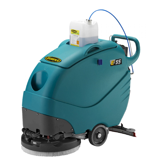
Page 12: Machine Description
E50 - E55 – M500 – M550 1. Tank 13. Charger plug protection 2. Broom holder 14. Level indicator and solution tank drain pipe 3. Solution adjustment knob 15. Battery compartment closure 4. Control board 16. Charger connection cable to the main socket 5. - Page 13 E50 – E55 – M500 – M550 1. Tank grip 2. Mobile connector 3. Fixed connector 4. Batteries 5. Battery unloading part 6. Prewashing wheel 7. Squeegee pressure adjustment wheel 8. Wheel 9. Forward drive motor (TRAC version) 10. Brush hub 11.
-
Page 14: Primary Functions And Controls
PRIMARY FUNCTIONS AND CONTROLS PANEL... - Page 15 BRUSH SWITCH By pressing the button towards position 1, the brush function starts. The brush will start turning when the drive bar is pressed. When the bar is released the brush stops. To the brush function is also connected the solenoid valve (if fitted) which permits automatically opening and closing the solution flow.
-
Page 16: Machine Setting
MACHINE PREPARATION MOUNTING THE SQUEEGEE Follow the instructions below to mount the squeegee to the machine: Park the machine on a flat surface, put the key in pos 0 and remove it; Put the squeegee lever in pos. 1 (squeegee in low position). -
Page 17: Adjusting The Squeegee
SQUEEGEE ADJUSTMENTS SQUEEGEE ANGLE ADJUSTMENT Lower the squeegee. Lift the regulator pos. 2 from its housing Release and remove the clips pos. 1 Turn the regulator pos. 2 anticlockwise to lift the tips Turn the regulator pos. 2 clockwise to lower the of the squeegee pos. -
Page 18: Squeegee Prewash Wheel
SQUEEGEE PREWASH WHEEL To perform prewash, position the wheel as follows: Slightly lift the squeegee by means of the lever pos. 1; Turn the wheel support pos. 2 in the direction indicated by the arrow until the lever rests on the squeegee body pos. 3; ... -
Page 19: Mounting The Abrasive Disc Onto The Disc Pad Holder
MOUNTING THE ABRASIVE DISC ONTO THE DISC PAD HOLDER The machine can operate with brushes or abrasive discs of various types mounted on special disc pad holders. Follow the instructions below to mount the abrasive disc onto the disc pad holder: ... -
Page 20: Brushes/Abrasive Disc Installation
FITTING THE BRUSH OR ABRASIVE DISC Brush engage device Lower the lever (pos. A) in horizontal position Place the brush (pos. B) - Page 21 From the drive position (pos. D) lower the brush desk, move it from right to links in order to make easy the correct mounting of the hub on the brush. Bring the key (pos. E) in pos. 1, pressing the button (pos. F) towards position 1.
-
Page 22: Adjusting The Machine Drive Direction
ADJUSTING THE MACHINE DRIVE DIRECTION IMPORTANT: this adjustment must be made with the machine operating, full of water, with squeegee lowered and vacuum on. If, during operation, the machine tends to move in the direction A indicated by the arrow, adjust the knob pos. 1 by screwing it (turn clockwise) thereby loading the spring. -
Page 23: Filling The Detergent Solution Tank
FILLING THE DETERGENT SOLUTION TANK The tank should be filled using clean water mixed with an appropriate detergent solution suited for the type of floor and for the dirty conditions of the floor and using a product suitable for cutting down foam. FIG. -
Page 24: Adjusting The Detergent Solution On The Brushes
ADJUSTING THE QUANTITY OF SOLUTION ON THE BRUSHES (WATER + DETERGENT) Adjust the quantity of solution on the brush by means of the knob shown in the image. When this knob is in position 0, the flow of solution is completely closed. As the knob is gradually turned towards the MAX position, the amount of solution gradually increases. -
Page 25: Using The Machine
USING THE MACHINE Our scrubber-dryers must be operated by properly trained authorized staff. Scrubber-dryers that do not operate properly must be taken out of service immediately. CHECK BEFORE USE Make sure to check the following before using the machine: ... -
Page 26: Periodic Servicing
PERIODIC SERVICING INTRODUCTION REGULAR AND PERIODIC SERVICING OF YOUR SCRUBBER GUARANTEES OUTSTANDING PERFORMANCE OF THE MACHINE AND ITS LONG LIFE. THE PAGES THAT FOLLOW CONTAIN THE INFORMATION THAT WILL HELP TO PLAN THE CARE AND THE SERVICING THAT THE SCRUBBER NEEDS. WARNING! DO NOT CARRY OUT ANY MAINTENANCE OPERATION NEITHER ON THE MACHINE NOR ON ITS COMPONENTS WITHOUT HAVING FIRST STOPPED THE MACHINE, PUT IT ON A FLAT FLOOR... -
Page 27: Recovery Tank Drain Valve Cleaning
Gradually open the valve by turning the device pos 3 and dosing the water leakage to avoid splashing; Once the tank has been emptied, remove the cover pos.4 and carefully wash the inside with water. Wash well to make sure all residues are removed, even the smallest ones (sand) and also clean the closing valve well so it is always in good operating condition;... -
Page 28: Draining And Cleaning The Solution Tank
DRAINING AND CLEANING THE SOLUTION TANK After completing the washing operation, in order to drain any leftover water from the solution tank, proceed as follows: Disengage the brush function and close the solution tap if the machine does not feature a solenoid valve and place the machine in raised-brush position;... -
Page 29: Cleaning The Detergent Solution Filter
CLEANING THE DETERGENT SOLUTION FILTER The machine is fitted with a filter on the duct that comes from the detergent solution tank. In theory, the solution located in this tank should not have any impurities as the buckets or containers used to fill the solution are supposed to be clean;... -
Page 30: Cleaning, Replacing And Checking The Installation Of The Squeegee Blades
CLEANING THE SQUEEGEE After completing the washing operation, clean the squeegee and make sure the blades are in good condition, and then proceed as follows: Bring the machine into a stop position in a flat surface area; Put the key in pos 0; ... - Page 31 Remove the butterfly nut pos. 2; Remove the rear blade blocking plate pos. 3; Remove the rear blade pos. 4; Remove the screws pos. 7-8-9 being careful not to mix them up as they have different lengths. Pos.
-
Page 32: Checking The Brush Plate Splashguard
FITTING, ADJUSTING AND CHECKING THE SPLASHGUARD To fit or remove the splashguard, proceed as follows: Fit the splashguard around the brush plate and insert it in the front part of the plates as shown in pos. 4; Fit the fixing plate pos. 2; ... - Page 33 POSITION 2: 5 A fuse for electronic drive board protection; POSITION 3: 30 A fuse for suction motor protection; POSITION 4: 30 A fuse for drive system protection. E50-M500 UNTIL FRAME 500005830515 S/N. 1514 E55-M550 UNTIL FRAME 055002060515 S/N. 1130 BRUSH MOTOR PROTECTION POS. 10;...
-
Page 34: Checking The Seal On The Cover
CHECK THE SEAL ON THE COVER The recovery tank cover gasket ensures the creation of the vacuum in the tank itself and this permits achieving a perfect vacuum on the squeegee. The integrity of the gasket is therefore very important for correct machine operation. -
Page 35: Clean The Cooling Grid Of The Vacuum Motor
CLEAN THE COOLING GRID OF THE VACUUM MOTOR To clean the cooling grid follow the instructions below: Bring the machine into a stop position in a flat surface area, turn it off; Remove the carter pos. 1; Check and eventually clean the cooling grid of the vacuum motor (pos. -
Page 36: Servicing And Maintenance For Scheduled Servicing
1° SERVICING AND MAINTENANCE FOR SCHEDULED SERVICING MONTH YEAR WORKING HOURS AFTER 100 HOURS DATE Check that the batteries clamps are not loosen or oxidized Check the cover gasket Make sure there are no loose screws or bolts ... - Page 37 3° SERVICING AND MAINTENANCE FOR SCHEDULED SERVICING MONTH YEAR WORKING HOURS AFTER 300 HOURS DATE Check that the batteries clamps are not loosen or oxidized Check the cover gasket Make sure there are no loose screws or bolts ...
- Page 38 GEAR REDUCTION MOTOR BRUSH E50-M500 CODE 900805 Check the motor carbon brushes and if necessary replace them when their length reaches 10 mm. Length of new motor carbon brush: 19 mm. Motor carbon brush code 640327. N°2 EACH MOTOR ...
- Page 39 MONTH YEAR WORKING HOURS DATE AT 600 HOURS AS AFTER 100 HOURS DISTRIBUTOR’S STAMP THE SCHEDULED SERVICING WAS CARRIED OUT BY NAME: _____________________________ SURNAME: _____________________________ SIGNATURE:_____________________________ MONTH YEAR WORKING HOURS AT 700 HOURS AS AFTER 200 HOURS DATE DISTRIBUTOR’S STAMP THE SCHEDULED SERVICING WAS CARRIED OUT BY NAME: _____________________________...
-
Page 40: Dimensional Technical Drawings
DIMENSIONAL DRAWINGS E50-M500 E55-M550... -
Page 41: Technical Chart
TECHNICAL CHART TECHNICAL CHARACTERISTICS MODELLO E50-BASE E50-TRAC E55-BASE E55-TRAC M500-BASE M500-TRAC M550-BASE M550-TRAC CLEANING PATH WITH BRUSH mm 475 mm 475 mm 545 mm 545 MAX BRUSH PRESSURE Kg 35 Kg 34 Kg 44 Kg 45 SOLUTION/RECOVERY TANK CAPACITY Lt 40 - Lt 50... -
Page 42: Recommended Spare Parts
RECOMMENDED SPARE PARTS USED FOR SERVICING. SERVICING OPERATIONS CAN BE CARRIED OUT BY THE USER HIMSELF ON CONDITON IT HAS PREVIOUSLY BEEN INSTRUCTED BY EITHER THE MACHINE OWNER OR HIS EMPLOYER... - Page 43 COD. 520136: 1,2 TYNEX BRUSH (E50-M500) COD. TE.25160: RED ABRASIVE DISC DA 21” 530 mm (E55-M550) COD. TE.27606: BLACK ABRASIVE DISC DA 19” 480 mm (E50-M500) COD. TE.30167: BLUE ABRASIVE DISC DA 21” 530 mm (E55-M550) ...
-
Page 44: Trouble-Shooting Chart
Flat battery (charger’s red led light The brush motor does not rotate Recharge it flashing ) Replace it Faulty fuse E50-M500 UNTIL FRAME 500005830515 S/N 1514 E55-M550 UNTIL FRAME 055002060515 S/N 1130 10. Brush motor protection fuse is engaged Refresh it 11. - Page 45 PROBLEM CAUSE SOLUTION If the drive does not work, check any red lights on 26. Diagnosis for led flashings the drive board (see picture). To do it, when the - SWITCHED OFF: NO ERRORS, NORMAL WORKING CONDITIONS machine stops, without turning the key off, open - 1 FLASHING: forward speed microswitch - Pull the drive control switch in O position the electrical board by removing the 4 screws and...
- Page 46 PROBLEM CAUSE SOLUTION Not enough suction on the squeegee 34. Recovery tank is full Empty it 35. Float on the recovery tank Switch off the vacuum motor and unblock the float ball 36. Valve on tank drainpipe open and safety Close the valve and put the cap cap removed 37.
-
Page 47: Product Warranty
PRODUCT WARRANTY Eureka S.p.A. warrants that our machine will be free from defects in material and workmanship for a period of 12 months from date of installation. Written notice of any claimed defect must be given to Eureka S.p.A. or its Authorized Sales/Service Representative within the warranty period and within thirty (30) days after such defect is discovered. -
Page 48: Installation Form For Warranty Approval
Warranty claims will be evaluated only if the following Installation Form will be sent by fax or by mail, filled in all its parts, to Eureka’s headquarter within thirty (30) days after the machine’s installation. PLEASE RETAIN THE ORIGINAL COPY WITHIN THE MANUAL. -
Page 49: Declaration Of Conformity
35013 CITTADELLA (PD) dichiariamo sotto la nostra esclusiva responsabilità che il prodotto LAVASCIUGA PAVIMENTI: MODELLI: E50 BASE – E50 TRAC E55 BASE – E55 TRAC al quale questa dichiarazione si riferisce è conforme alle seguenti norme: Sicurezza del macchinario, Concetti fondamentali, principi generali di progettazione Specifiche e principi tecnici - UNI EN 12100-1, UNI EN 12100-2 ...