
Related Manuals for Eureka E65


Summary of Contents for Eureka E65
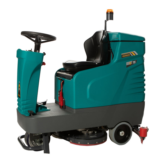
- Page 1 INSTRUCTION MANUAL E65 - E75/2 - E83 EUREKA S.p.A. VIALE DELL’ARTIGIANATO 30/32, 35013 CITTADELLA (PD) ITALY Fax. ++39 -049 – 9481899 Tel. ++39 - 049 - 9481800 INTERNET : www.eurekasweepers.com E-MAIL : info@eurekasweepers.com...
-
Page 3: Table Of Contents
• CLEANING THE VACUUM FILTER • CHECKING THE GASKET ON THE COVER • CHECKING OR REPLACING FUSES • DRIVE WHEEL PERIODICAL CHECKING DIMENSIONAL TECHNICAL DRAWINGS SPARE PARTS RECOMMENDED – E65 SPARE PARTS RECOMMENDED – E75/2 SPARE PARTS RECOMMENDED – E83 SCHEDULED SERVICING TROUBLESHOOTING CHART... -
Page 4: Introduction
INTRODUCTION Our company, a leading industrial cleaning machine manufacturer, is delighted to welcome you to the ranks of our scrubber owners and it trusts that you will get the greatest satisfaction from the use of the machine. We are certain that while using the machine you will have the opportunity to see the quality, solidity, and possibilities for use for yourselves. -
Page 5: Warnings
ATTENTION! BEFORE USING THE MACHINE OR CARRYING OUT ANY OPERATION ON IT, ALL THE PROCEDURES AND WARNINGS DESCRIBED IN THIS MANUAL MUST BE READ AND UNDERSTOOD. RIGOROUS COMPLIANCE WITH THE REGULATIONS AND INSTRUCTIONS CONTAINED IN IT, TOGETHER WITH THE OPERATOR’S ATTENTION AND PRUDENCE WILL BE THE BEST GUARANTEE AGAINST ACCIDENTS THAT COULD OCCUR AT WORK. - Page 6 RESPONSIBILITIES OF THE OPERATOR The operator is responsible for the day-to-day servicing of the machine. - The operator must care for the machine and keep it in good operating condition. - The operator must inform his or her superior or the technical department when scheduled maintenance is requested in the case of damage or breakage.
- Page 7 CLEANING AND MAINTENANCE The machine must be cleaned by persons who have received proper instruction for the purpose, who know how to cut off the sources of energy and who know the characteristics of the machine so as not to find themselves in a hazardous situation.
- Page 8 PRECAUTIONS FOR THE SAFETY OF OPERATORS AND TECHNICIANS - The machine must not be used by non-authorised personnel who have not been trained to use it properly or by people who are under the influence of substances that could alter their nervous reflexes (alcohol, psycho pharmaceuticals, drugs etc.) - Do not use the machine in inflammable areas or where there is the danger of explosions;...
-
Page 9: Disposal
DISPOSAL SPENT OILS Spent oils must not be thrown away into the environment under any circumstances. They must be given to authorised Collectors in compliance with the regulations currently in force. Temporary storage must be inside watertight containers with sealed lid to avoid contact with the environment and with rainwater. -
Page 10: Transporting The Machine By Manual Pushing
TRANSPORTING THE MACHINE BY MANUAL PUSHING The machine is equipped with an electromagnetic brake (pos. 1) that keeps the machine braked when off or when the drive pedal is not pushed. When moving the machine manually, the brake must be disengaged by pulling the lever (pos. -
Page 11: Installing Batteries
INSTALLING BATTERIES CAUTION: USE PROTECTIVE GLOVES AND GOGGLES WHEN HANDLING BATTERIES, AVOIDING ANY CONTACT WITH THE ACID INSIDE THE BATTERIES. Refer to the specification sheet for battery types and sizes suitable for the machine. L= 260 mm L= 180 mm L=535 mm L=685 mm Follow the instructions below to mount the batteries to the machine:... -
Page 12: Recharging Batteries
RECHARGING BATTERIES USING AN EXTERNAL CHARGER Follow the instructions below to charge the batteries: • Stop the machine in a levelled area and turn it off; • Make sure to read the battery charger instruction manual before charging the batteries; •... - Page 13 13. Brush motor 1. Hand-wheel 14. Easy lift pedal 2. Seat 15. Drive wheel 3. Max. level floating device of the recovery tank 16. Front wheel 4. Vacuum motor filter inspection cap 17. Forward and reverse foot pedal 5. Vacuum motor filter 18.
- Page 14 1. Solution adjustment lever 11. Machine rear anchoring point 2. Squeegee lifting lever 12. Solution tank level 3. Control panel 13. Squeegee inclination adjustment knob 4. Brush plate lifting pedal 14. Solution tank filling cap 5. Brush plate pedal release lever 15.
-
Page 15: Main Functions And Controls
MAIN FUNCTIONS AND CONTROLS CONTROL PANEL HOUR METRE (OPTIONAL) KEY-OPERATED SWITCH Turn it clockwise (position 1) to turn on the machine. WARNING: After turning off the machine by the key, wait until 3 -4 seconds before starting it again HORN SWITCH Press this button to emit the sound. -
Page 16: Emergency Situations
BRUSH DRIVE BUTTON Push this switch to position 1 to activate the brush function. The brushes will start spinning when the brush plate is lowered and once the forward and reverse gear pedal is pushed. When the pedal is released the brushes will spin for another 2 seconds before stopping. The solenoid valve is connected to the brush function;... - Page 17 With the jumper inserted, the charge indicator is set for lead acid batteries (FIG.A). Without the jumper, the charge indicator is set for gel/agm batteries (FIG.B). If the indicator is set for gel/agm batteries and you want to install lead acid batteries, please contact EUREKA for the jumper.
-
Page 18: Installing The Squeegee
INSTALLING THE SQUEEGEE Follow the instructions below to assemble the squeegee: • Park the machine in a levelled area, turn it off and remove the keys; • Lift the squeegee support with the provided lever (pos. 9); • Place the squeegee (pos. 1) in the support (pos. 5) and centre the knobs (pos. -
Page 19: Moving The Brush Plate
MOVING THE BRUSH PLATE Use the pedal (pos. 3) to move the brush plate (pos. 1). Follow the instructions below to lower the brush plate: • Use the heel of the foot (pos. 5) to push the release lever (pos. 2). Use the toes of the foot (pos. -
Page 20: Installing Brushes And Abrasive Discs
INSTALLING BRUSHES AND ABRASIVE DISCS To attach the brushes or the driving devices with the abrasive discs, follow the instructions below: • Turn the key (pos. 7) to position 0 to turn off the machine, making sure that the brush plate is raised; •... -
Page 21: Filling The Detergent Solution Tank
FILLING THE DETERGENT SOLUTION TANK The tank should be filled using clean water mixed with appropriate detergent solution suited for the type of floor and based on the condition of the floor. A product suitable for cutting down excess foam should also be used. •... -
Page 22: Splash Guard Lifting For Pre-Washing
SPLASH GUARD LIFTING FOR PRE-WASHING When using the machine to wash floors particularly filthy, it is recommended to pre-wash the floor, allowing the chemical product of the detergent solution to act more effectively to remove dirt. Therefore, wash the floor without collecting the solution with the squeegee. During this operation, it is recommended to lift the splash guard of the machine to allow an even distribution of the detergent product on the floor. -
Page 23: Detergent Dosing System (Optional)
DETERGENT DOSING SYSTEM (OPTIONAL) Fix the tank containing the detergent by strap pos.6 and put in the tank tube POS. 7. To operate the detergent dosing pump turn ON the toggle switch pos.4. When the pump is on the light Pos.2 comes on green. WARNING: THE PUMP DETERGENT DOSING PUMP WORKS ONLY WHEN THE BRUSHES ARE ACTIVE. -
Page 24: Using The Machine
USING THE MACHINE Our scrubber-dryers must be operated by authorised staff who have been properly trained. Scrubber-dryers that do not operate properly must be taken out of service immediately. CHECK BEFORE USE Make sure to check the following before using the machine: •... -
Page 25: Maintenance
MAINTENANCE INTRODUCTION SERVICING YOUR SCRUBBER-DRYER REGULARLY AND PERIODICALLY WILL ENSURE BETTER PERFORMANCE AND MORE DURABILITY. THE FOLLOWING PAGES CONTAIN INFORMATION THAT WILL HELP YOU PLAN THE MAINTENANCE AND CARE FOR THE MACHINE NEEDS. WARNING DO NOT PERFORM ANY MAINTENANCE ON THE MACHINE OR ANY OF ITS COMPONENTS WITHOUT TURNING OFF THE MACHINE AND UNPLUGGING THE BATTERY CONNECTOR. - Page 26 CLEANING THE VACUUM FILTER The machine is fitted with a stainless-steel mesh filter used to protect the vacuum motor. Weekly, or even daily for certain spaces, we suggest to check if filter is clean and if there is material that can block the aspiration Follow the instructions below to clean the filter: •...
-
Page 27: Draining And Cleaning The Solution Tank
DRAINING AND CLEANING THE SOLUTION TANK After completing the washing operation, in order to drain any leftover water from the solution tank and clean the tank, proceed as follows: • Lift the brush plate and turn off the switch on the control panel; •... - Page 28 CLEANING THE SQUEEGEE Once the washing operation is completed, clean the squeegee and check the integrity of the blades. Proceed as follows: • Lift the brush plate and turn off the switch on the control panel; • Lift the squeegee using the provided lever and turn off the switch on the control panel after 10 seconds;...
- Page 29 REPLACING THE REAR BLADE Follow the instructions below to rotate or replace the rear blade: • Remove the squeegee from the machine; • Remove the blade locking plate (pos. 5) by unlocking the retainer (pos. 3).This retainer is fitted with a safety device that keeps it from opening involuntarily.
-
Page 30: Cleaning The Detergent Solution Filter
REPLACING THE SPLASH GUARD BLADES Follow the instructions below to replace the side blades of the splash guard: • Lift the brush plate and turn off the switch on the control panel; • Turn off the machine and remove the key. REPLACING THE SIDE BLADES •... -
Page 31: Checking The Gasket On The Cover
CHECKING THE GASKET ON THE COVER The gasket on the cover of the recovery tank seals the tank properly, providing a better vacuum performance on the squeegee. For this reason, it is very important to keep the gasket intact in order for the machine to work properly. -
Page 32: Checking Or Replacing Fuses
CHECKING OR REPLACING FUSES To check and replace fuses proceed as follows: • Stop the machine in a levelled area and turn the key to position 0; • Unplug the mobile connector (pos. 8); • Remove the cap from the hand-wheel (pos. 1); •... - Page 33 • Use a 3mm Allen key to remove the 10 fixing screws (pos. 3) of the control panel; • Remove the control panel (pos. 6), lift it and attach it to the shaft of the wheel using the provided bracket (pos. 7), ensuring not to jerk as this could damage the electrical system;...
- Page 34 CHECKING TO BE MADE EVERY 400 HOURS ON THE DRIVE WHEEL DRIVE WHEEL Check the motor carbon brushes and if necessary replace them when their length reaches 7mm. Length of new motor brush: 20mm. Motor brush code: 640291. 4 X MOTOR. ELECTRO BRAKE •...
-
Page 35: Dimensional Technical Drawings
DIMENSIONAL TECHNICAL DRAWINGS... - Page 36 SPARE PARTS RECOMMENDED FOR THE ORDINARY MAINTENANCE TO BE CONDUCTED BY QUALIFIED OPERATORS TRAINED ACCORDINGLY BY THE OWNER OR EMPLOYER • CODE 210495: FRONT BUMPER ROLLER • CODE 210586: BUMPER ROLLER • CODE 340104: COVER GASKET 1.12 METRES • CODE 360397: SQUEEGEE FRONT RUBBER IN LINATEX – 4mm - (STANDARD) •...
- Page 37 E75/2 SPARE PARTS RECOMMENDED FOR THE ORDINARY MAINTENANCE TO BE CONDUCTED BY QUALIFIED OPERATORS TRAINED ACCORDINGLY BY THE OWNER OR EMPLOYER • CODE 210495: FRONT BUMPER ROLLER • CODE 210586: BUMPER ROLLER • CODE 340104: COVER GASKET 1.12 METRES • CODE 360387: SQUEEGEE FRONT RUBBER IN LINATEX - 4 mm - (STANDARD) •...
- Page 38 SPARE PARTS RECOMMENDED FOR THE ORDINARY MAINTENANCE TO BE CONDUCTED BY QUALIFIED OPERATORS TRAINED ACCORDINGLY BY THE OWNER OR EMPLOYER • CODE 210495: FRONT BUMPER ROLLER • CODE 210586: BUMPER ROLLER • CODE 340104: COVER GASKET 1.12 METRES • CODE 360481: SPLASH GUARD RUBBER IN PRIMOTANO – 4.7 mm - ( 2 PER MACHINE-OPTIONAL) •...
- Page 39 For further informations regarding the servicing, consult the pages of the manual related to maintenance SERVICING AND MAINTENANCE FOR SCHEDULED 1° SERVICING OF E65 - E75/2 - E83 - M650 - M750 - M830 MONTH YEAR WORKING HOURS AFTER 100 HOURS DATE ...
-
Page 40: Scheduled Servicing
SERVICING AND MAINTENANCE FOR SCHEDULED 2° SERVICING OF E65 - E75/2 - E83 - M650 - M750 - M830 MONTH YEAR WORKING HOURS AFTER 200 HOURS DATE Check that the batteries clamps are not loosen or oxidized Check the batteries fluid level ... - Page 41 SERVICING AND MAINTENANCE FOR SCHEDULED 3° SERVICING OF E65 - E75/2 - E83 - M650 - M750 - M830 MONTH YEAR WORKING HOURS AFTER 300 HOURS DATE Check that the battery clamps are not loosen or oxidized Check the batteries fluid liquid ...
- Page 42 SERVICING AND MAINTENANCE FOR SCHEDULED 4° MAINTENANCE OF E65 - E75/2 - E83 - M650 - M750 - M830 MONTH YEAR WORKING HOURS AFTER 400 HOURS DATE Check that the batteries clamps are not loosen or oxidized Check the batteries fluid level ...
- Page 43 SERVICING AND MAINTENANCE FOR SCHEDULED 5° SERVICING OF E65 - E75/2 - E83 - M650 - M750 - M830 MONTH YEAR WORKING HOURS AFTER 500 HOURS DATE MOTOR CARBON BRUSHES CHECK CHECK AND REMOVE THE MOTOR CARBON BRUSHES ONE AT A TIME SO AS NOT TO INVERT THEM. THE...
- Page 44 THE SCHEDULED SERVICING WAS CARRIED OUT BY: DISTRIBUTOR’S STAMP NAME: _______________________________________________ SURNAME: ___________________________________________ SIGNATURE: _________________________________________ NOTE:...
- Page 45 SERVICING AND MAINTENANCE FOR SCHEDULED SERVICING OF E65 - E75/2 - E83 - M650 - M750 - M830 MONTH YEAR WORKING HOURS AFTER 600 HOURS AS 100 HOURS DATE DISTRIBUTOR’S STAMP THE SCHEDULED SERVICING WAS CARRIED OUT BY: NAME: _______________________________________________...
- Page 46 TROUBLESHOOTING TABLE WARNING! ANY MAINTENANCE SERVICE OR TEST, EXCEPT FOR THOSE DESCRIBED IN THE MANUAL, MUST BE PERFORMED EXCLUSIVELY BY AN AUTHORISED ASSISTANCE CENTRE (AAC) BEFORE ANY INTERVENTIONS CHECK THE CORRECT VOLTAGE OF THE BATTERY: 24V PROBLEM CAUSE SOLUTION The battery does not charge Faulty or worn elements Replace the battery The instruments on the panel do not...
- Page 47 -fuse or internal relay damaged works CORRECTLY upon ignition and that the battery cables and motor cables are connected correctly. If the problem persists, replace the traction - Locked or damaged electrobrake board. - Check the correct functioning and the absorptions (absorption 0.9 –...
-
Page 48: Technical Chart
SCRUBBER-DRYER MODEL MODEL TECHNICAL CHART MODEL E 75/2 E 83 E 65 SCRUBBING WIDTH WITH mm 650 mm 760 mm 810 BRUSH BRUSH PRESSURE Kg 52 Kg 52 Kg 52 SOLUTION / RECOVERY Lt 110 - Lt 125 Lt 110 - Lt 125 Lt 110 - Lt 125 TANK CAPACITY PRODUCTIVITY... -
Page 49: Product Warranty
PRODUCT WARRANTY Eureka S.p.A. warrants that its machine will be free from defects in materials and workmanship for a period of 12 months from the date of installation. Written notice of any claimed defect shall be given to Eureka S.p.A. or its Authorized Sales/Service Representative within the warranty period and within thirty (30) days after such defect is discovered. - Page 50 Warranty claims will be evaluated only if the following Installation Form is sent by fax or by mail, fully filled in, to Eureka’s headquarters within thirty (30) days after the machine’s installation. PLEASE RETAIN THE ORIGINAL COPY WITHIN THE MANUAL.
- Page 51 35013 CITTADELLA (PD) dichiariamo sotto la nostra esclusiva responsabilità che il prodotto LAVASCIUGA PAVIMENTI: MODELLO: E65 – E75/2 – E83 al quale questa dichiarazione si riferisce è conforme alle seguenti norme: ▪ Sicurezza del macchinario, Concetti fondamentali, principi generali di progettazione Specifiche e principi tecnici - UNI EN 12100-1, UNI EN 12100-2 ▪...