Table of Contents
Advertisement
Quick Links
Advertisement
Table of Contents

Related Manuals for Eureka E51M


Summary of Contents for Eureka E51M
- Page 1 INSTRUCTION MANUAL E51M E61M _______________________________________________ EUREKA S.p.a. Viale dell’artigianato 30/32, 35013 CITTADELLA (PD) ITALY Fax. ++39 -049 – 9481899 Tel. ++39 - 049 - 9481800 INTERNET: www.eurekasweepers.com E-MAIL: info@eurekasweepers.com...
-
Page 3: Table Of Contents
TABLE OF CONTENTS Topic PAGE INTRODUCTION MACHINE IDENTIFICATION WARNINGS GENERAL WARNINGS AND RECOMMENDATIONS DISPOSAL TRANSPORT AND MOVEMENT UNPACKING LIFTING THE TANK BATTERIES INSTALLATION MACHINE DESCRIPTION PRIMARY FUNCTIONS AND CONTROLS MACHINE SETTING MOUNTING THE SQUEEGEE ADJUSTING THE SQUEEGEE MOUNTING THE ABRASIVE DISC ONTO THE DISC PAD HOLDER ... -
Page 4: Introduction
INTRODUCTION Our company, a leading industrial cleaning machine manufacturer, is delighted to welcome you to the ranks of our scrubber owners and it trusts that you will get the greatest satisfaction from the use of the machine. We are certain that while using the machine you will have the opportunity to see the quality, solidity and possibilities for use by yourselves. -
Page 5: Warnings
ATTENTION! BEFORE USING THE MACHINE OR CARRYING OUT ANY OPERATION ON IT, ALL THE PROCEDURES AND WARNINGS DESCRIBED IN THIS MANUAL MUST BE READ AND UNDERSTOOD. RIGOROUS COMPLIANCE WITH THE REGULATIONS AND INSTRUCTIONS CONTAINED IN IT, TOGETHER WITH THE OPERATOR’S ATTENTION AND PRUDENCE WILL BE THE BEST GUARANTEE AGAINST ACCIDENTS THAT COULD OCCUR AT WORK. - Page 6 ONLY EXTINGUISH FIRES WITH POWDER FIRE EXTINGUISHERS RESPONSIBILITIES OF THE OPERATOR The operator is responsible for the day-to-day servicing of the machine - The operator must care for the machine and keep it in good operating condition - The operator must inform his or her superior or the technical department when scheduled maintenance is requested in the case of damage or breakage - The operator must not carry people, animals or objects on the machine.
- Page 7 CLEANING AND MAINTENANCE The machine must be cleaned by persons who have received proper instruction for the purpose, who know how to cut off the sources of energy and who know the characteristics of the machine so as not to find themselves in a hazardous situation. Clean the machine coverings, the panels and commands with cloths soaked in water or a detergent solution.
-
Page 8: Disposal
DISPOSAL SPENT OILS Spent oils must not be thrown away into the environment under any circumstances. They must be given to authorised Collectors in compliance with the regulations currently in force. Temporary storage must be inside watertight containers with sealed lid to avoid contact with the environment and with rainwater. -
Page 9: Unpacking
UNPACKING Make sure that all the parts indicated in the following list are present before unpacking the machine: Squeegee; battery box; battery jumper L = 25 cm, fitted with terminals and terminal covers; battery cable L = 51.5 cm, fitted with connector, terminals and terminal covers; ... -
Page 10: Lifting The Tank
LIFTING THE TANK Follow the instructions below to lift the tank: Bring the machine into a stop position in a flat surface area, put on the brake and turn the key into position 0: Unblock the tank by means of the two levers pos. 1 placed on both sides; ... -
Page 11: Batteries Installation
INSTALLING BATTERIES CAUTION: USE PROTECTIVE GLOVES AND GOGGLES WHEN HANDLING BATTERIES, AVOIDING ANY CONTACT WITH THE ACID INSIDE THE BATTERIES. CAUTION: THE BATTERY CHARGER AND THE CONTROL BOARD ARE SET ACCORDING TO THE TYPE OF BATTERIES SHOWN IN THE SHEET ATTACHED TO THE USER’S MANUAL. IF YOU WANT TO MOUNT BATTERIES WITH A DIFFERENT AMPERAGE OR OF A DIFFERENT TYPE (I.E. -
Page 12: Machine Description
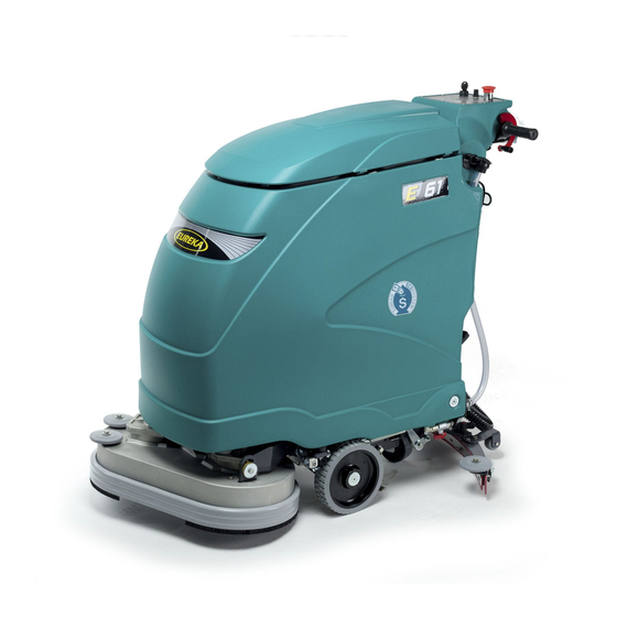
E 51 – M 510 Control panel 19. Tap Tank lid 20. Battery charger Suction filter lid 21. Squeegee lever Suction filter 22. Battery mobile connector Safety suction filter 23. Brake pedal Filter support 24. Squeegee Drum of the clean water filter 25. - Page 13 E61 – M610 1. Control panel 19. Tap 2. Tank lid 20. Battery charger 3. Suction filter lid 21. Squeegee lever 4. Suction filter 22. Battery mobile connector 5. Suction safety filter 23. Brake pedal 6. Filter support 24. Squeegee 7.
-
Page 14: Primary Functions And Controls
PRIMARY FUNCTIONS AND CONTROLS CONTROL PANEL DRIVE OR REVERSE DRIVE CONTROL Rotate the mechanism forward to drive the machine. Rotate the mechanism backwards for reverse drive. The speed of the machine will either increase or decrease progressively ---------- when rotating the control progressively forward or backwards, it will go from speed level 0 (machine in halt position) to the maximum speed set with the potentiometer (position 4) located on the instrument panel. - Page 15 With the jumper inserted, the charge indicator is set for lead acid batteries (FIG.A). Without the jumper, the charge indicator is set for gel/agm batteries (FIG.B). If the indicator is set for gel/agm batteries and you want to install lead acid batteries, please contact EUREKA for the jumper.
- Page 16 CONTROL PANEL KEY-OPERATED SWITCH Turn it clockwise (position 1) to turn on the machine. RED LIGHT: DRIVE ALARM Indicates any faults in the drive board of the drive motor. The number of flashes indicates the type of fault (consult the troubleshooting table).
- Page 17 BRUSH DRIVE BUTTON Push this switch to position 1 to activate the brush function. The brushes will start spinning when the forward and reverse gear pedal is pushed. When the pedal is released the brushes will spin for another 3 seconds before stopping.
-
Page 18: Machine Setting
SETTING UP THE MACHINE MOUNTING THE SQUEEGEE Follow the instructions below to mount the squeegee to the machine: park the machine on a flat surface, put on the brake (if available) and remove the key (if available); Position the squeegee lever into position 1 (raised position). -
Page 19: Mounting The Abrasive Disc Onto The Disc Pad Holder
MOUNTING THE ABRASIVE DISC ONTO THE DISC PAD HOLDER The machine can operate with brushes or abrasive discs of various types mounted on special disc pad holders. Follow the instructions below to mount the abrasive disc onto the disc pad holder: ... - Page 20 MOUNTING THE BRUSH OR ABRASIVE DISC ON MACHINE Follow the instructions below to mount the brushes or disc pad holders with abrasive discs: Turn off the machine and press the key into position 0. Lift the brush plate (pos.2) with the pedal (pos.1). ...
-
Page 21: Filling The Detergent Solution Tank
FILLING THE DETERGENT SOLUTION TANK The tank should be filled using clean water mixed with an appropriate detergent solution suited for the type of floor and for the dirty conditions of the floor and using a product suitable for cutting down foam. Use the mouth of the tank (see position 3) to fill the solution tank. -
Page 22: Adjusting The Detergent Solution On The Brushes
ADJUSTING THE QUANTITY OF SOLUTION ON THE BRUSHES (WATER + DETERGENT) The quantity of the solution on the brushes can be adjusted using the lever in position 1. The lever in upward position will shut-off the flow of the solution completely. -
Page 23: Operation
OPERATION Release the parking brake (if available); Turn the key to position 1 on the TRAC and ECO versions; Lower the squeegee by turning the special lever; Lower the brush plate using the pedal; Turn on the brush and the suction fan using the buttons in the instrument panel; ... -
Page 24: Periodic Servicing
PERIODIC SERVICING INTRODUCTION REGULAR AND PERIODIC SERVICING OF YOUR SCRUBBER GUARANTEES OUTSTANDING PERFORMANCE OF THE MACHINE AND ITS LONG LIFE. THE PAGES THAT FOLLOW CONTAIN THE INFORMATION THAT WILL HELP TO PLAN THE CARE AND THE SERVICING THAT THE SCRUBBER NEEDS. WARNING! DO NOT CARRY OUT ANY MAINTENANCE OPERATION NEITHER ON THE MACHINE NOR ON ITS COMPONENTS WITHOUT HAVING FIRST:... -
Page 25: Draining And Cleaning The Solution Tank
After draining the tank, make sure to clean it thoroughly using water. To ease this operation, use two fingers to rotate the 2 plates in the direction indicated by the arrows (see position 7) and remove the cover (see position 8); ... -
Page 26: Cleaning, Replacing And Checking The Installation Of The Squeegee Blades
CLEANING THE SQUEEGEE After completing the washing operation, clean the squeegee and make sure the blades are in good condition, then proceed as follows: Bring the machine into a stop position in a flat surface area; Put on the brake (if available); ... - Page 27 Follow the instructions below to rotate or replace the rear blade: Remove the squeegee from the machine; Remove the blade locking plate (see position 5) by unlocking the retainer (see position 3). This retainer is fitted with a safety device that keeps it from opening involuntarily.
-
Page 28: Cleaning The Detergent Solution Filter
CLEANING THE DETERGENT SOLUTION FILTER The machine is fitted with a filter on the duct that comes from the detergent solution tank. In theory, the solution located in this tank should not have any impurities as the buckets or containers used to fill the solution are supposed to be clean, in addition there is a filter in the mouth of the tank that filters the water. -
Page 29: Cleaning The Suction Filter
CLEANING THE SUCTION FILTER The machines are fitted with a washable cartridge filter on the suction duct, which provides two functions: To filter the air vacuumed by the squeegee, trapping dust before releasing it into the environment, without putting it back into the air;... -
Page 30: Checking Or Replacing Fuses In The Electric Panel
CHECKING OR REPLACING FUSES CHECKING OR REPLACING FUSES IN THE FRONT SWITCHBOARD To check or replace the fuses on the switchboard proceed as follows: Drain both tanks into the special drainage areas; Bring the machine into a stop position in a flat surface area and put on the brake; ... -
Page 31: Checking Or Replacing Fuses In The Charger
CHECKING OR REPLACING FUSES IN THE BATTERY CHARGER ALL VERSIONS To check or replace the fuses beneath the instrument panel proceed as follows: Turn off the key and unplug the battery connector as specified in the previous paragraph; Open the fuseholder cover (pos.1) ... -
Page 32: Recharcing Batteries
RECHARGING BATTERIES To charge the batteries follow the instructions below: Bring the machine into a stop position in a flat surface available); Before charging the battery make sure to scrupulously follow battery charger instruction manual provided with the machine; ... -
Page 33: Dimensional Technical Drawings
DIMENSIONAL DRAWINGS VERSIONS: E51 – M510 VERSIONS: E61 – M610 DIMENSIONAL DRAWINGS... -
Page 34: Recommended Spare Parts
RECOMMENDED SPARE PARTS USED FOR SERVICING. SERVICING OPERATIONS CAN BE CARRIED OUT BY THE USER HIMSELF ON CONDITON IT HAS PREVIOUSLY BEEN INSTRUCTED BY EITHER THE MACHINE OWNER OR HIS EMPLOYER... - Page 35 RECOMMENDED SPARE PARTS USED FOR SERVICING. SERVICING OPERATIONS CAN BE CARRIED OUT BY THE USER HIMSELF ON CONDITON IT HAS PREVIOUSLY BEEN INSTRUCTED BY EITHER THE MACHINE OWNER OR HIS EMPLOYER COD. 330142: BUMPER DISC COD. 340104: LID GASKET MT. 1,82 ...
-
Page 36: Trouble-Shooting Chart
TROUBLE-SHOOTING CHART WARNING! ANY OTHER TYPE OF SERVICE OPERATION OR TEST, EXCEPTION MADE FOR THOSE SHOWN IN THE PRESENT MANUAL, MUST BE CARRIED OUT BY AUTHORISED SERVICE CENTRES ONLY BEFORE ANY INTERVENTIONS CHECK THE CORRECT VOLTAGE OF THE BATTERY: 24V PROBLEM CAUSE SOLUTION... -
Page 37: Technical Chart
PROBLEM CAUSE SOLUTION - 8 FLASHINGS: either the power fuse or the Check that the 30A power fuse (pos. 4 on the power relay is faulty fuse-holder) from + battery till the traction board is OK and that the battery and motor wires are properly connected If necessary, replace the traction board. - Page 38 TECHNICAL SPECIFICATIONS SCRUBBER-DRYERS TECHNICAL MODEL SPECIFICATIONS E51M E61M M510M M610M SCRUBBING WIDTH WITH mm 530 mm 610 BRUSH BRUSH PRESSURE Kg 25 Kg 25 CAPACITY OF SOLUTION Lt 40 - Lt 56 Lt 40 - Lt 56 TANK – RECOVERY TANK...
-
Page 39: Scheduled Servicing
SERVICING For further informations regarding the servicing, consult the pages of the manual related to maintenance SERVICING AND MAINTENANCE FOR SCHEDULED 1° SERVICING OF E51 M - E61 M - M510 M - M610 M MONTH YEAR WORKING HOURS AFTER 100 HOURS DATE ... - Page 40 SERVICING AND MAINTENANCE FOR SCHEDULED 2° SERVICING OF E51 M - E61 M - M510 M - M610 M MONTH YEAR WARKING HOURS AFTER 200 HOURS DATE Check that the batteries clamps are not loosen or oxidized Check the cover gasket ...
- Page 41 SERVICING AND MAINTENANCE FOR SCHEDULED 3° SERVICING OF E51 M - E61 M - M510 M - M610 M MONTH YEAR WORKING HOURS AFTER 300 HOURS DATE Check that the batteries clamps are not loosen or oxidized Check the cover gasket ...
- Page 42 SERVICING AND MAINTENANCE FOR SCHEDULED 4° SERVICING OF E51 M- E61 M - M510 M - M610 M MONTH YEAR WORKING HOURS AFTER 400 HOURS DATE Check that the batteries clamps are not loosen or oxidized Check the cover gasket ...
- Page 43 SERVICING AND MAINTENANCE FOR SCHEDULED 5° SERVICING OF E51 M - E61 M - M510 M - M610 M MONTH YEAR WORKING HOURS AFTER 500 HOURS DATE MOTOR CARBON BRUSHES CHECKS CHECK AND REMOVE THE MOTOR CARBON BRUSHES ONE AT A TIME SO AS NOT TO INVERT THEM. THE MOTOR CARBON BRUSHES SETTLE AND WEAR DIFFERENTLY THE ONE FROM THE OTHER, CONSEQUENTLY IF THESE ARE INSPECTED AND PUT BACK ON AGAIN BECAUSE THEY ARE NOT FULLY WORN, THEY MUST BE REFITTED IN THE SAME POSITION.
- Page 44 SERVICING AND MAINTENANCE FOR SCHEDULED SERVICING OF E51 M - E61 M - M510 M - M610 M MONTH YEAR WORKING HOURS AFTER 600 HOURS AS 100 HOURS DATE DISTRIBUTOR’S STAMP THE SCHEDULED SERVICING WAS CARRIED OUT BY: NAME: _______________________________________________ SURNAME: ___________________________________________ FIRMA: _______________________________________________ MONTH...
-
Page 45: Product Warranty
PRODUCT WARRANTY Eureka S.p.A. warrants that our machine will be free from defects in material and workmanship for a period of 12 months from date of installation. Written notice of any claimed defect must be given to Eureka S.p.A. or its Authorized Sales/Service Representative within the warranty period and within thirty (30) days after such defect is discovered. -
Page 46: Installation Form For Warranty Approval
Warranty claims will be evaluated only if the following Installation Form will be sent by fax or by mail, filled in all its parts, to Eureka’s headquarter within thirty (30) days after the machine’s installation. PLEASE RETAIN THE ORIGINAL COPY WITHIN THE MANUAL. -
Page 47: Declaration Of Conformity
ENCL. N. A1 DICHIARAZIONE DI CONFORMITÁ Noi: EUREKA S.p.A. Unipersonale Viale dell’Artigianato 30/32 35013 CITTADELLA (PD) dichiariamo sotto la nostra esclusiva responsabilità che il prodotto LAVASCIUGA PAVIMENTI: MODELLI: E51M E61M al quale questa dichiarazione si riferisce è conforme alle seguenti norme: ...