Table of Contents
Advertisement
Advertisement
Table of Contents

Related Manuals for Rangemaster Nexus 110 Dual Fuel


Summary of Contents for Rangemaster Nexus 110 Dual Fuel
- Page 1 USER GUIDE & INSTALLATION INSTRUCTIONS Nexus 110 Dual Fuel / Steam U111021 - 01...
- Page 2 Terms & Conditions 1. This is my Rangemaster is open to residents of UK mainland only, aged 18 years & over. 2. All entries should be submitted to the advertised e-mail address, or Rangemaster UK Facebook, Instagram or Twitter page using the advertised hashtag &...
-
Page 3: Table Of Contents
Contents Before You Start... Cleaning Your Cooker Personal Safety Essential Information Electrical Connection Safety Hotplate Burners If You Smell Gas Ceramic Hotplate Peculiar Smells The Griddle Cooling Fan Grills Ventilation Multifunction Oven Maintenance Steam Cavity Hob Care Cleaning Table Grill/Glide-out Grill™ Care Troubleshooting Cooker Care Installation... -
Page 5: Before You Start
Before You Start... Your cooker should give you many years of and will retain heat even after you have trouble-free cooking if installed and operated stopped cooking. Care should be taken to correctly. It is important that you read this avoid touching heating elements. - Page 6 WARNING: THE APPLIANCE MUST BE Fig. 1.1 EARTHED. Note: The cooker must be connected to the correct electrical supply as stated on the voltage label on the cooker, through a suitable cooker control unit incorporating a double- 10 mm² max pole switch, having a contact separation of at least 3 mm in all poles.
-
Page 7: If You Smell Gas
In your own interest and that of safety, it is minutes with the grill pan in position, pushed • law that all gas appliances be installed by a fully back and the grill door open. qualified person(s). Make sure the room is well ventilated to the outside air (see ‘Ventilation’... - Page 8 DO NOT use hotplate protectors, foil or Foods for frying should be as dry as • • hotplate covers of any description. These possible. Frost on frozen foods or moisture may affect the safe use of your hotplate on fresh foods can cause hot fat to bubble burners and are potentially hazardous to up and over the sides of the pan.
- Page 9 Accidental damage may cause the door • Fig. 1.3 glass panel to fracture. Keep oven vent ducts unobstructed. • DO NOT use harsh abrasive cleaners or • sharp metal scrapers to clean the oven door ArtNo.324-0001 Steam burst glass since they can scratch the surface, which may result in shattering of the glass.
-
Page 10: Hob Care
Avoid warming an empty pan. Doing so Warming Zone Care • may damage both the heating zone and NEVER attempt to cook directly on the • pan. heating zone. Only certain types of glass, glass-ceramic, DO NOT use the heating zone surface as a •... -
Page 11: Cooker Care
DO NOT put the burner heads in a Cooker Care • dishwasher. As steam can condense to water droplets on the cool outer trim of the oven, it may be NEVER use caustic or abrasive cleaners as • necessary during cooking to wipe away any these will damage the surface. -
Page 12: Cooker Overview
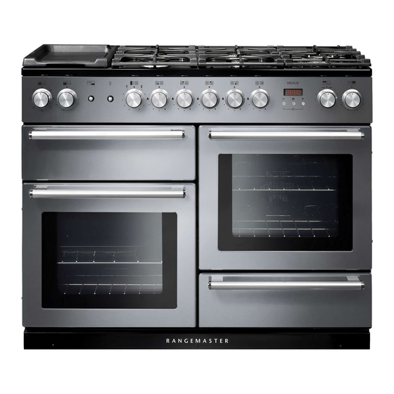
Cooker Overview Fig. 2.1 The 110 dual fuel cooker (Fig. 2.1) has the following features: Fig. 2.2 4 hotplate burners, a Wok Burner and a Ceramic Multizone hotplate Control Panel Glide-out Grill™ with 4 position Trivet Multifunction Oven Steam cavity Bread Proving/Storage Drawer Hotplate Burners The labels by each of the control knobs indicates which area... -
Page 13: Wok Burner
If and when you let go of the control knob or the burner goes Fig. 2.3 out, then the FSD has not been bypassed. Turn the control knob to the OFF position and wait for one minute before you try again, this time making sure to hold in the control knob for slightly longer. -
Page 14: The Ceramic Hotplate
The Ceramic Hotplate Fig. 2.11 The hotplate area on the left-hand side is dual purpose. It can be used either as a ceramic hob to heat a pan in the usual way (Fig. 2.11) or it can be used to heat the supplied griddle plate. -
Page 15: The Griddle
The Griddle Plate Fig. 2.16 The griddle plate (Fig. 2.17) is designed to fit securely on the locating pins over the ceramic heating area (Fig. 2.18). DO NOT try to use it over one of the gas burners. It will not be securely held and you may damage the non-stick finish. -
Page 16: The Glide-Out Grill
The Glide-out Grill™ Fig. 2.21 Open the door and pull the grill pan carriage forward using the handle (Fig. 2.21). The grill has two elements that allow either the whole area of the pan to be heated or just the right-hand half. Adjust the heat to suit by turning the control knob. -
Page 17: Bread Proving Drawer
Rangemaster Good Housekeeping Cookery book. Pre-heat the drawer so that it is warm and ready for your dough. -
Page 18: Cleaning
Cleaning Clean the inside of the drawer with hot soapy water and a soft cloth, rinse and dry. The Bread Proving Drawer is ideal for storing baking trays and other cooking utensils. It can get warm, so do not store anything in it that may melt or catch fire. -
Page 19: The Multifunction Oven
The Multifunction Oven The clock must be set to the time of day before the oven Symbol Function will work. See the section on ‘The Clock’ for instructions on A full cooking function, even heat setting the time of day. throughout, great for baking References to ‘left-hand’... - Page 20 ECO Mode Fig. 3.2 This setting saves energy, cooking in fanned mode, for foods requiring a cooking time of 45 minutes or less. No preheating . Note: The oven door must remain closed during ECO mode. Failure to do so will result in the oven continuing to cook after the pre-set 45 minutes.
-
Page 21: Accessories
Accessories Fig. 3.3 Front Glide-out Oven Shelves bracket Rear stop The left-hand oven is supplied with 2 glide-out oven shelves. To fit the glide-out shelf, hook the front of the shelf onto the runners as shown (Fig. 3.3). The rear of the shelf should rest on the runners, in front of the rear stop (Fig. - Page 22 The Handyrack (Optional extra) Fig. 3.11 The Handyrack (Fig. 3.11) fits to the left-hand oven door only. Food cooking on it is easy to attend to, because it is accessible when the door is open. The maximum weight that can be held by the Handyrack is 5.5 kg (12 lb).
- Page 23 Once the specified time has elapsed an alarm will Fig. 3.17 sound. It will stop automatically after 10 seconds. To cancel the minute minder, and enter a new time, tap the clock button whilst the [ ] symbol is active. To stop the multifunction oven after a specific time Set the cooking function and temperature (see “Operating the Multifunction Oven”...
-
Page 24: Cooking Tips
Cooking Tips General oven tips The wire shelves should always be pushed firmly to the back Tips on cooking with the timer of the oven. If you want to cook more than one dish, choose dishes that Baking trays with food cooking on them should be placed require approximately the same cooking time. -
Page 25: Cooking Table
Cooking Table The oven control settings and cooking times given in the table below are intended to be used as a Top (T) guide only. Individual tastes may require the temperature to be altered to provide a preferred result. ArtNo.050-0007 Centre (C) Oven shelf positions Food is cooked at lower temperature in a fan oven than in a conventional oven. -
Page 26: The Steam Cavity
The Steam Cavity Fig. 4.1 Water Tank Door Seal 1 x Rack 1 x Pan 1 x Perforated Pan Door Sponge The Steam Cavity (right-hand) Fig. 4.2 The steam cavity is shown in Fig. 4.1. Fig. 4.2 shows the touch sensitive control panel for the steam cavity. -
Page 27: Operating The Steam Cavity
Operating the Steam Cavity Fig. 4.4 Note: The steam cavity may start a pump out cycle (Fig. 4.12) when first turned on. This is normal and it should be allowed to complete. The cycle will take approximately 2 minutes. Touch and hold the standby button to switch the steam cavity on (Fig. -
Page 28: Steam Cavity Functions
Steam Cavity Functions Fig. 4.13 The steam cavity has three main functions: steam grill descale Switch the oven on and tap the [ + ] or [ - ] buttons to scroll through these functions. Program Modes The steam cavity has pre-programmed modes for different food types. -
Page 29: The Clock / Timer
The Clock / Timer Fig. 4.14 The clock above the multi-function oven must be set to the time of day before the multi-function oven or steam cavity will work. See "Setting the clock" on page 18. Note: The steam cavity control does not show the time of day. -
Page 30: Cleaning Your Cooker
Cleaning Your Cooker Essential Information Fig. 5.1 Isolate the electricity supply before carrying out any thorough cleaning. Allow the cooker to cool. Never use paint solvents, washing soda, caustic cleaners, biological powders, bleach, chlorine based bleach cleaners, coarse abrasives or salt. Do not mix different cleaning products –... -
Page 31: Ceramic Hotplate
Ceramic Hotplate Fig. 5.5 Daily Care First of all, make sure that the heat indicator light is off and that the cooking surface is cool. Apply a small dab of ceramic cleaning cream in the centre of the area to be cleaned. Dampen a clean paper towel and work the cream onto the cooking surface. -
Page 32: Grills
Grills Fig. 5.6 The grill pan and trivet should be washed in hot soapy water. Alternatively, the grill pan can be washed in a dishwasher. After grilling meats or any foods that soil, leave to soak for a few minutes immediately after use. Stubborn particles may be removed from the trivet using a nylon brush. -
Page 33: Multifunction Oven
Control Panel and Doors Fig. 5.10 Avoid using any abrasive cleaners, including cream cleaners. For best results, use a liquid detergent. The same cleaner can also be used on the doors. Alternatively, use a soft cloth wrung out in clean hot soapy water. You can use the same method for cleaning the control panel and knobs. -
Page 34: Steam Cavity
Steam Cavity Fig. 5.12 Before cleaning your oven or performing maintenance, please switch off the power supply. In order to prolong the service life of steam cavity, please note the following points: The enameled or stainless steel parts should be washed with lukewarm water without using any abrasive powders or corrosive substances which could scratch, stain and damage the oven. -
Page 35: Cleaning Table
Cleaning Table Cleaners listed (Table 5.1) are available from supermarkets or electrical retailers as stated. For enamelled surfaces use a cleaner that is approved for use on vitreous enamel. Regular cleaning is recommended. For easier cleaning, wipe up any spillages immediately. Hotplate Part Finish... -
Page 36: Troubleshooting
Troubleshooting Hotplate/Cooktop ignition or hotplate burners faulty Food is cooking too slowly, too quickly, or burning Is the power on? Is the clock illuminated? Cooking times may differ from your previous oven. If not, there maybe something wrong with the power supply. Check that you are using the recommended temperatures and shelf positions –... - Page 37 Multifunction oven light is not working Fig. 6.1 The bulb has probably burnt out. You can buy a replacement bulb (which is not covered under the warranty) from a good electrical shop. Ask for a 40W - 230V halogen lamp (G9) (Fig.
- Page 38 Error Codes Multifunction oven Error Code Error description Comment HE 1 Oven sensor NTC short circuit or open circuit HE 2 Meat probe short circuit Not applicable HE 3 Communication problem between UI and power PCB Steam cavity Error Code Error description Comment HE 1...
-
Page 39: Installation
INSTALLATION Check the appliance is electrically safe and gas sound when you have finished. Installation Dear Installer In the UK the cooker must be installed in accordance with: Before you start your installation, please complete the details below, so that, if your customer has a problem relating to •... -
Page 40: Location Of Cooker
INSTALLATION Check the appliance is electrically safe and gas sound when you have finished. Location of Cooker Checking the parts: The cooker may be installed in a kitchen/kitchen diner but 3 pan supports Wok cradle NOT in a room containing a bath or shower. This appliance is designed for domestic cooking only. -
Page 41: Positioning The Cooker
INSTALLATION Check the appliance is electrically safe and gas sound when you have finished. Positioning the Cooker Fig. 7.1 Fig. 7.1 and Fig. 7.2 shows the minimum recommended 75 mm 75 mm distance from the cooker to nearby surfaces. 650 mm The cooker should not be placed on a base. -
Page 42: Fitting The Stability Bracket Or Chain
INSTALLATION Check the appliance is electrically safe and gas sound when you have finished. Lowering the Two Rear Rollers Fig. 7.5 To adjust the height of the rear of the cooker, first fit a 13 mm spanner or socket wrench onto the hexagonal adjusting nut (Fig. -
Page 43: Conversion To Another Gas
INSTALLATION Check the appliance is electrically safe and gas sound when you have finished. Conversion to Another Gas If the appliance is to be converted to another gas do the conversion at this point. See the conversion section of these instructions. -
Page 44: Gas Connection
INSTALLATION Check the appliance is electrically safe and gas sound when you have finished. Gas Connection Fig. 7.11 Pipework Pipework This must be in accordance with the relevant standards. The flexible hose (not supplied with the cooker) must be in accordance with the relevant standards. Hoses may be purchased at most builders’... -
Page 45: Electrical Connection
INSTALLATION Check the appliance is electrically safe and gas sound when you have finished. Electrical Connection Current Operated Earth Leakage Breakers The cooker must be installed by a qualified electrician, in The combined use of your induction cooker and other accordance with all relevant British Standards/Codes of domestic appliances may cause nuisance tripping, so we Practice (in particular BS 7671), or with the relevant national... -
Page 46: Conversion To Lp Gas
WARNING – SERVICING TO BE CARRIED OUT ONLY BY AN AUTHORISED PERSON Disconnect from electricity and gas before servicing. Check appliance is safe when you have finished. Conversion to LP Gas Check the ‘Technical Data’ section at the back of the book Fig. -
Page 47: Pressure Testing
WARNING – SERVICING TO BE CARRIED OUT ONLY BY AN AUTHORISED PERSON Disconnect from electricity and gas before servicing. Check appliance is safe when you have finished. Pressure Testing Connect the appliance to the gas supply. The gas pressure can be measured at one of the hotplate injectors (not a wok burner). -
Page 48: Circuit Diagram
Circuit Diagram Steam Oven 1.1kW 1.1kW The connections shown in the circuit diagram are for single-phase. The ratings are for 230 V 50 Hz. Code Description Code Description Code Colour Grill Energy Regulator Neon Blue Brown Left Hand Grill Element Thermal Cut-Out Black Right Hand Grill Element... -
Page 49: Power Pcb
Power PCB Connector P1 Connector P2 A4 A9 A3 A8 A2 A7 A1 A6 A11 A12 Protective Earth POWER PCB BOARD Con 5 Con 7 Con 10 Con 1 Con 8 Con 4 11 Function UI (X43) Steam Oven UI (X44) The connections shown in the circuit diagram are for single-phase. - Page 50 29 mbar 230/400 V 50 Hz Propane 37 mbar See the appliance badge for test pressures. Dimensions Model NEXUS 110 Dual Fuel / Steam Overall height minimum 905 mm maximum 930 mm Overall width 1092 mm Overall depth 608 mm excluding handles, 648 mm including handles...
- Page 51 Hotplate Efficiency Brand Rangemaster Model Identification Nexus Size Type Dual Fuel / Steam Type of Hob Number of gas burners Auxiliary / Small Burner (EE gas burner) Semi Rapide / Medium Burner (EE gas burner) Semi Rapide / Medium Burner (EE gas burner)
- Page 52 Oven Data Brand Rangemaster Model identification Nexus Type of oven Electric Mass Number of cavities Left-hand Efficiency Fuel type Electric Cavity type Multifunction Power - conventional Power - forced air convection Volume Litres Energy consumption (electricity) - conventional kWh / cycle 1.01...
- Page 53 NOTES...
- Page 54 NOTES...
- Page 55 • Has not been repaired by persons or organisations other than those authorised to act on behalf of AGA Rangemaster. Date of Purchase Exceptions: • Items not included under the free 1 year guarantee Installer’s Name &...
- Page 56 Registered Office: c/o Aga Rangemaster, Meadow Lane, Long Eaton, Nottingham, NG10 2GD Rangemaster continuously seeks improvements in specification, design and production of products and thus, alterations take place periodically. Whilst every effort is made to produce up-to-date literature, this brochure should not be regarded as...