Rangemaster 110 Ceramic User's Manual & Installation Instructions
Range cooker
Hide thumbs
Also See for 110 Ceramic:
- User's manual & installation instructions (44 pages) ,
- User manual (40 pages) ,
- User manual (36 pages)
Table of Contents
Advertisement
Quick Links
Advertisement
Table of Contents

Related Manuals for Rangemaster 110 Ceramic


Summary of Contents for Rangemaster 110 Ceramic
-
Page 1: Installation Instructions
Britain’s No.1 Range Cooker USER GUIDE & INSTALLATION INSTRUCTIONS 110 Ceramic... - Page 2 We offer cookware to work perfectly with all fuel types manufactured by Rangemaster, including induction hobs. You can be assured of functionality with style, as well as the quality and meticulous attention to detail you expect from the pioneers of range cooking.
-
Page 3: Table Of Contents
Main Oven Light Customer Care Storage Circuit Diagrams Cooking Tips Tips on Cooking with the Timer Technical Data General Oven Tips Hotplate Efficiency Data Cooking Table Oven Data Cleaning Your Cooker Grills Control Panel and Doors Cleaning Table 110 Ceramic U110038-06... -
Page 5: Before You Start
1. Before You Start... This User Guide covers a number of different models. Personal Safety Although some of the illustrations will look different to DO NOT modify this appliance. your particular model the functions will be the same. We This appliance is not intended for use by persons hope the meaning is clear. -
Page 6: Hob Care
Never leave the hotplate unattended at high heat settings. Fig. 1.1 Pans boiling over can cause smoking, and greasy spills may catch on fire. Use a deep fat thermometer whenever possible to prevent fat overheating beyond the smoking point. NEVER leave a chip pan unattended. Always heat fat slowly, and watch as it heats. -
Page 7: Cooker Care
Always LIFT pans off the hob. Sliding pans may cause marks Fig. 1.5 and scratches (Fig. 1.4). Always turn the control to the OFF position before removing a pan. DO NOT place anything between the base of the pan and the hob surface (e.g. -
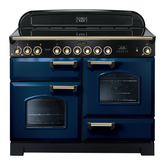
Page 8: Cooker Overview
DocNo.020-0002 - Overview - 90 Ceramic - Generic Fig. 2.1 ºC ºC ArtNo.190-0001 - 110 Ceramic annotated GENERIC The 110 ceramic cooker (Fig. 2.1) has the following features: Fig. 2.2 Ceramic hob Control panel Separate grill or glide-out grill (depending on model) - Page 9 (Fig. 2.7). Warmer (Rangemaster only) On the right of the hob is the warmer (Fig. 2.8). Use the warmer for keeping food warm while the final touches are put to a meal.
-
Page 10: The Grill / Glide-Out Grill
The Grill / Glide-out Grill Fig. 2.10 Open the door and pull the grill pan (Fig. 2.10) or carriage (Fig. 2.11) forward using the handle. The grill has two elements that allow either the whole area of ArtNo.330-0003 - Grill pan w handle pulled forwards the pan to be heated or just the right-hand half. -
Page 11: The Ovens
The Ovens Function The clock must be set to the time of day before the ovens To thaw small items in the oven without Defrost will work. See the following section on ‘The Clock’ for heat instructions on setting the time of day. A full cooking function, even heat Fan oven throughout, great for baking... - Page 12 cooking time, as the heat at the top of the oven is greater Multifunction Oven Functions than at the base, when using this function. Rapid Response (Classic Deluxe only) The Rapid Response setting enables you to preheat This is a fast intensive form of cooking; keep an eye on the the oven faster than normal.
- Page 13 Operating the Ovens Fig. 2.14 Conventional zoned ovens and fan ovens Turn the oven knob to the desired temperature (Fig. 2.14). The oven indicator light will glow until the oven has reached the temperature selected. It will then cycle on and off during cooking.
-
Page 14: The Clock
The Clock Fig. 2.16 You can use the clock to turn the left-hand oven on and off. ArtNo.300-0005 2BC minute minder setting Note: When using the timer functions, first set the clock as required before setting the oven temperature and selecting the oven function (multi-function ovens only). - Page 15 To Stop the Multifunction Oven at a Specific Fig. 2.21 ArtNo.301-0008 2BC Time of Day Stopping the oven 2 You have set the required temperature and function mode for the Multifunction Oven and you would like the Multifunction Oven to automatically stop. TOP TIP Make a note of the current time so you do not forget.
- Page 16 symbol on the display will disappear and the word Fig. 2.28 ‘AUTO’ will flash (Fig. 2.27). Setting the 6-button Clock The 6-button LCD clock is shown in Fig. 2.28. When the clock is first connected the display flashes ( 0.00 ) and ( ArtNo.302-0002 - 6BC annotated alternately.
-
Page 17: Key Lock
AUTO is showing, you want to reset to manual Fig. 2.38 Fig. 2.39 cooking To return to manual cooking from any automatic setting, the ‘cook period’ must be cancelled. Press and hold the [E] button and then press the [ –] button until the display reads ArtNo.302-0009 - Activating ArtNo.302-0008 - the key lock 2... -
Page 18: Oven Shelves
Accessories Fig. 2.43 Shelf guard Oven Shelves The oven shelves (Fig. 2.43) are retained when pulled forward but can be easily removed and refitted. Pull the shelf forward until the back of the shelf is stopped by the shelf stop bumps in the oven sides (Fig. 2.44). Front Lift up the front of the shelf so the back of the shelf will pass under the shelf stop and then pull the shelf forward... -
Page 19: Cooking Tips
3. Cooking Tips Tips on Cooking with the Timer General Oven Tips If you want to cook more than one dish, choose dishes that The wire shelves should always be pushed firmly to the back require approximately the same cooking time. However, of the oven. -
Page 20: Cooking Table
4. Cooking Table DocNo.031-0004 - Cooking table - electric & fan single cavity The oven control settings and cooking times given in the table below are intended to be used Top (T) AS A GUIDE ONLY. Individual tastes may require the temperature to be altered to provide a ArtNo.050-0007 preferred result. -
Page 21: Cleaning Your Cooker
5. Cleaning Your Cooker DocNo.040-0004 - Cleaning - 110 ceramic GENERIC Isolate the electricity supply before carrying out any major Fig. 5.1 cleaning. Then allow the cooker to cool. NEVER use paint solvents, washing soda, caustic cleaners, biological powders, bleach, chlorine based bleach cleaners, coarse abrasives or salt. -
Page 22: Grills
Grills Fig. 5.2 The grill pan and trivet should be washed in hot soapy water. After grilling meats or any foods that soil, leave to soak for a few minutes immediately after use. Stubborn particles may be removed from the trivet using a nylon brush. Alternatively, the grill pan can be washed in a dishwasher. - Page 23 Glass Fronted Door Panels (some models) Fig. 5.7 The oven door front panels can be taken off so that the glass panels can be cleaned. Move the cooker forward to gain access to the sides (see the ‘Moving the Cooker’ section under ‘Installation’).
-
Page 24: Cleaning Table
Cleaning Table Cleaners listed (Table 5.1) are available from supermarkets or electrical retailers as stated. For enamelled surfaces use a cleaner that is approved for use on vitreous enamel. Regular cleaning is recommended. For easier cleaning, wipe up any spillages immediately. Hotplate Part Finish... -
Page 25: Troubleshooting
6. Troubleshooting Interference with and repairs to the hob MUST NOT Food is cooking too slowly, too quickly, or burning be carried out by unqualified persons. Do not try Cooking times may differ from your previous to repair the hob as this may result in injury and oven. - Page 26 The oven light is not working Fig. 6.1 The bulb has probably blown. You can buy a replacement bulb (which is not covered under the guarantee) from most electrical stores. Ask for an Edison ArtNo.324-0005 Oven light bulb screw fitting 15 W 230 V lamp, FOR OVENS (Fig. 6.1). It must be a special bulb, heat resistant to 300 °C.
-
Page 27: Installation
INSTALLATION Check the appliance is electrically safe when you have finished. 7. Installation Dear Installer You will need the following equipment to complete the cooker installation satisfactorily: Before you start your installation, please complete the details • Multimeter (for electrical checks). below, so that, if your customer has a problem relating to You will also need the following tools: your installation, they will be able to contact you easily. -
Page 28: Positioning The Cooker
INSTALLATION Check the appliance is electrically safe when you have finished. Positioning the Cooker ArtNo.090-0028 - 90 cooker min spacing GENERIC Fig. 7.1 Fig. 7.1 and Fig. 7.2 show the minimum recommended 75 mm 75 mm distance from the cooker to nearby surfaces. 650 mm The cooker should not be placed on a base. -
Page 29: Completing The Move
INSTALLATION Check the appliance is electrically safe when you have finished. Lowering the Two Rear Rollers Fig. 7.5 To adjust the height of the rear of the cooker, first fit a 13 mm spanner or socket wrench onto the hexagonal adjusting nut (Fig. -
Page 30: Electrical Connection
INSTALLATION Check the appliance is electrically safe when you have finished. Electrical Connection Fig. 7.8 The cooker must be installed by a qualified electrician, in accordance with all relevant British Standards/Codes of Practice (in particular BS 7671), or with the relevant national and local regulations. -
Page 31: Final Fitting
INSTALLATION Check the appliance is electrically safe when you have finished. Final Fitting Fig. 7.10 Fitting the Handles and Handrail (depending on model) Remove the 4 mm Allen screws from the doors (Fig. 7.10). Fit the door handles and secure using the 4 mm screws. ArtNo.215-0026 - Handle gaskets fixed The handles should be above the fixings. -
Page 32: Circuit Diagrams
2.02kW 1.1kW 1.56kW bk/w ArtNo.082-0023 - 110 Ceramic (hob warmer only) - circuit diagram Connections shown in the circuit diagram are for single -phase. Ratings are for 230 V 50 Hz. Code Description Code Colour Left-hand end dual circuit hob energy regulator... - Page 33 2.02kW 1.1kW 1.1kW 1.56kW bk/w ArtNo.082-0024 - 110 Ceramic (hob) - circuit diagram Connections shown in the circuit diagram are for single-phase. The ratings are for 230 V 50 Hz. Code Description Code Colour Blue Left-hand end dual circuit hob energy regulator...
- Page 34 1.1kW 1.1kW 1.56kW bk/w ArtNo.082-0020 - 110 Ceramic (hob) - Classic DL circuit diagram Connections shown in the circuit diagram are for single-phase. The ratings are for 230 V 50 Hz. Code Description Code Colour Left-hand end dual circuit hob energy regulator...
- Page 35 ArtNo.082-0025 - 110 Ceramic (oven) - Circuit diagram The connections shown in the circuit diagram are for single-phase. The ratings are for 230 V 50 Hz. Code Description Code Description Code Colour...
-
Page 36: Multifunction Oven
Multifunction Oven Elan To terminal P6 on the warmer hob controller switch br v P033458 P028728 P033458 The connections shown in the circuit diagram are for single- phase. The ratings are for 230 V 50 Hz. Code Description Code Description Code Colour Grill energy regulator Clock... - Page 37 P038434 P033458 P033458 br br br ArtNo.082-0021 - 110 ceramic (oven) - Classic DL circuit diagram The connections shown in the circuit diagram are for single-phase. The ratings are for 230 V 50 Hz. Code Description Code Description Code Colour...
-
Page 38: Technical Data
515 mm excluding handles, 663 mm including handles Total depth: Professional+ 604 mm excluding handles, 645 mm including handles Total depth: Rangemaster 600 mm excluding handles, 650 mm including handles Total depth: Toledo 605 mm excluding handles, 655 mm including handles Hotplate Ratings 1.65kW... -
Page 39: Hotplate Efficiency Data
Hotplate Efficiency Data Classic, Classic Deluxe, Elan, Kitchener, Professional+ and Toledo Brand Rangemaster Classic Classic Deluxe Elan Model Identification Kitchener Professional+ Toledo Size Type Ceramic Type of Hob Radiant Number of electric zones Zone 1 - Ø cm 14.5 Heating Technology Energy Consumption (ECElectric cooking) - Wh/kg Zone 2 - Ø... - Page 40 Hotplate Efficiency Data Rangemaster Brand Rangemaster Model Identification Rangemaster Size Type Ceramic Type of Hob Radiant Number of electric zones Zone 1 - Ø cm 21.0 Heating Technology Energy Consumption (ECElectric cooking) - Wh/kg Zone 2 - Ø cm 14.5...
-
Page 41: Oven Data
Oven Data Classic, Kitchener, Professional+, Rangemaster, Toledo Brand Rangemaster Classic Model identification Kitchener Professional+ Mass Rangemaster Model identification Toledo Mass Type of oven Electric Number of cavities Left-hand Efficiency Fuel type Electric Cavity type Convection Power - conventional Power - forced air convection... - Page 42 Oven Data Classic Deluxe and Elan Brand Rangemaster Model identification Classic Deluxe Mass Model identification Elan Mass Type of oven Electric Number of cavities Left-hand Efficiency Fuel type Electric Cavity type Multifunction Power - conventional Power - forced air convection...
- Page 43 0800 804 6261 or depending on your mobile network tariff you can For a competitive quote and to arrange for a Rangemaster approved call free on 0370 789 5107. engineer to attend, call Consumer Services on: 0800 804 6261 or...
- Page 44 Registered in England and Wales. Registration No. 354715 Registered Office: Juno Drive, Leamington Spa, Warwickshire, CV31 3RG Rangemaster continuously seeks improvements in specification, design and production of products and thus, alterations take place peri- odically. Whilst every effort is made to produce up-to-date literature, this booklet should not be regarded as an infallible guide to current...