Rangemaster 110 Induction G5 User's Manual & Installation Instructions
Range cooker
Hide thumbs
Also See for 110 Induction G5:
- User manual (44 pages) ,
- User's manual & installation instructions (40 pages)

Related Manuals for Rangemaster 110 Induction G5


Summary of Contents for Rangemaster 110 Induction G5
-
Page 1: Installation Instructions
Britain’s No.1 Range Cooker USER GUIDE & INSTALLATION INSTRUCTIONS 110 Induction G5... - Page 2 We offer cookware to work perfectly with all fuel types manufactured by Rangemaster, including induction hobs. You can be assured of functionality with style, as well as the quality and meticulous attention to detail you expect from the pioneers of range cooking.
-
Page 3: Table Of Contents
Hints on Using Your Induction Cooker Conventional Oven Tips on Cooking with the Timer General Oven Tips Technical Data Cooking Table Connection Dimensions Cleaning Your Cooker Ratings Hotplate Efficiency Data Grills Oven Data Control Panel and Doors Ovens Cleaning Table 110 Induction G5 U110202-07... -
Page 5: Before You Start
1. Before You Start... Ventilation Your cooker should give you many years of trouble-free cooking if installed and operated correctly. It is important CAUTION: The use of a cooking appliance results in that you read this section before you start, particularly if you the production of heat and moisture in the room in have not used an induction cooker before. - Page 6 Fig. 1.1 Take care when touching the marked cooking areas of the hob. When the ovens are on, DO NOT open doors for longer than necessary to insert and remove contents. The control knobs will become hot and this may cause cosmetic failure. ArtNo.324-0001 Steam burst When using the grill, make sure that the grill pan is in position and pushed fully in, otherwise the...
-
Page 7: Hob Care
DO NOT use water on grease fires and never pick Fig. 1.2 up a flaming pan. Turn off the controls and then ArtNo.312-0001 Not cooking surface smother a flaming pan on a surface unit by covering the pan completely with a well fitting lid or baking tray. -
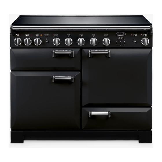
Page 8: Cooker Overview
2. Cooker Overview ArtNo.025-0005 - Overview - 90 induction - 2 button clock & GO grill Fig. 2.1 ºC ºC ArtNo.190-0002 - 110 Induction annotated GENERIC Your 110 induction cooker (Fig. 2.1) has the following Fig. 2.2 features: 5 induction cooking zones Control panel A separate grill or glide-out grill (depending on model) A conventional or multifunction oven (programmable,... - Page 9 The very best pans have bases that are very slightly curved Model Programmable Oven up when cold (Fig. 2.3). If you hold a ruler across the bottom Classic right-hand oven you will see a small gap in the middle. When they heat up the metal expands and lies flat on the cooking surface.
- Page 10 Residual Heat Indicator, H Auomatic Heat-up Time at Power Level 100% (min:sec) After use, a cooking zone will remain hot for a while as heat dissipates. When a cooking zone is switched off the residual 0:48 heat indicator symbol [H ], will appear in the display. This 2:24 shows that the cooking zone temperature is above 60 °C and may still cause burns.
- Page 11 Low Temperature Setting, L1/L2 Maximum Operating Time Power Level Each cooking area is equipped with 2 low temperature settings: 2 hours L1 and L2 L1 will maintain a temperature of about 40 °C – ideal for • 6 hours gently melting butter or chocolate. 6 hours L2 will maintain a temperature of about 90 °C –...
-
Page 12: The Grill / Glide-Out Grill
The Grill / Glide-out Grill Fig. 2.9 CAUTION: This appliance is for cooking purposes only. It must not be used for other purposes, for example room heating. CAUTION: Accessible parts may be hot when the grill ArtNo.330-0003 - Grill pan w handle pulled forwards is in use. -
Page 13: The Ovens
The Ovens Function The clock must be set to the time of day before the To thaw small items in the oven without Defrost programmable oven will work. See the following section heat on ‘The Clock’ for instructions on setting the time of day. A full cooking function, even heat Fan oven throughout, great for baking... - Page 14 cooking time, as the heat at the top of the oven is greater Multifunction Oven Functions than at the base, when using this function. Rapid Response (Classic Deluxe & Professional Deluxe) The Rapid Response setting enables you to preheat This is a fast intensive form of cooking; keep an eye on the the oven faster than normal.
-
Page 15: Main Oven Light
The Fan Oven Fig. 2.13 Fan ovens circulate hot air continuously, which means faster, more even cooking. The recommended cooking temperatures for a fan oven are generally lower than those for a non-fan oven. Note: Please remember that all cookers vary so temperatures in your new ovens may differ to those in your previous cooker. -
Page 16: The Clock
The Clock Fig. 2.18 The clock must be set to the time of day before the oven ArtNo.300-0005 2BC will work. minute minder setting 1. Once the cooker is connected and switched on, the display will start to flash. 2. To set the time, turn and hold the Timer (A) knob to the Clock (C) setting and at the same time turn the Adjusting (B) knob either clockwise or counter-clockwise (Fig. - Page 17 To Stop the Multifunction Oven at a Specific ArtNo.301-0008 2BC Fig. 2.23 Time of Day Stopping the oven 2 You have set the required temperature and function mode for the Multifunction Oven and you would like the Multifunction Oven to automatically stop. TOP TIP Make a note of the current time so you do not forget.
- Page 18 To Start and Stop the Multifunction Oven ArtNo.301-0010 2BC Fig. 2.26 Setting the cooking time The Multifunction Oven allows you to automatically start and stop by a combination of the length of the cooking time and the stop time. Giving you the flexibilty to cook casseroles etc while you are out.
- Page 19 The 6-button Clock Fig. 2.33 Setting the Time of Day The 6-button LCD clock is shown in Fig. 2.33. When the clock is first connected the display flashes ( 0.00 ) and ( alternately. Press and hold both the [C] and [D] buttons down ArtNo.302-0002 - 6BC annotated (Fig.
- Page 20 AUTO is Showing, You Want to Reset to Manual Cooking Fig. 2.43 Fig. 2.44 To return to manual cooking from any automatic setting, the ‘cook period’ must be cancelled. Press and hold the [E] button and then press the [ –] button until the display reads ( 0.00 ).
-
Page 21: Accessories
Accessories Fig. 2.48 Oven Shelves Shelf guard The oven shelves (Fig. 2.48) are retained when pulled forward but can be easily removed and refitted. Pull the shelf forward until the back of the shelf is stopped by the shelf stop bumps in the oven sides (Fig. 2.49). Lift up the front of the shelf so the back of the shelf will pass Front under the shelf stop and then pull the shelf forward... -
Page 22: Storage
Storage Fig. 2.55 The bottom drawer is for storing oven trays and other cooking utensils. ArtNo.340-0002 110 removing the drawer It can get very warm, so do not store anything in it that may melt or catch fire. Never store flammable materials in the drawer. -
Page 23: Cooking Tips
3. Cooking Tips WARNING! Refer to Before You Start... chapter. Hints on Using Your Induction Cooker General Oven Tips If you have not used an induction cooker before please be The wire shelves should always be pushed firmly to the back aware of the following: of the oven. -
Page 24: Cooking Table
4. Cooking Table DocNo.031-0004 - Cooking table - electric & fan single cavity The oven control settings and cooking times given in the table below are intended to be used Top (T) AS A GUIDE ONLY. Individual tastes may require the temperature to be altered to provide a ArtNo.050-0007 preferred result. -
Page 25: Cleaning Your Cooker
5. Cleaning Your Cooker Isolate the electricity supply before carrying out any major Fig. 5.1 cleaning. Allow the cooker to cool. All parts of the cooker can be cleaned with hot soapy water. Take care that no surplus water seeps into the appliance. Remember to switch the electricity supply back on and reset the clock before reusing the cooker. -
Page 26: Grills
Grills Fig. 5.2 The grill pan and trivet should be washed in hot soapy water. Alternatively, the grill pan can be washed in a dishwasher. After grilling meats or any foods that soil, leave to soak for a few minutes immediately after use. Stubborn particles may be removed from the trivet using a nylon brush. -
Page 27: Control Panel And Doors
Control Panel and Doors Fig. 5.7 Avoid using any abrasive cleaners, including cream cleaners. For best results, use a liquid detergent. The same cleaner can also be used on the doors. Alternatively, use a soft cloth wrung out in clean hot soapy water. You can use the same method for cleaning the control panel and knobs. -
Page 28: Cleaning Table
Cleaning Table Cleaners listed (Table 5-1) are available from supermarkets or electrical retailers as stated. For enamelled surfaces use a cleaner that is approved for use on vitreous enamel. Regular cleaning is recommended. For easier cleaning, wipe up any spillages immediately. Hotplate Part Finish... -
Page 29: Troubleshooting
6. Troubleshooting DocNo.050-0001 - Troubleshooting - Induction GENERIC Interference with and repairs to the hob MUST NOT The cooling fan be carried out by unqualified persons. Do not try The induction hob incorporates a cooling fan. This to repair the hob as this may result in injury and cooling fan is active when either the grill or ovens damage to the hob. - Page 30 Fascia illumination is not coming on (Hi-LITE only) Is the power on? The appliance has developed a fault that cannot be rectified by the user. Please contact your installer or a qualified repair engineer. Food is cooking too slowly, too quickly, or burning Cooking times may differ from your previous oven.
- Page 31 The oven light is not working Fig. 6.1 The bulb has probably blown. You can buy a replacement bulb (which is not covered under the guarantee) from most electrical stores. Ask for an Edison ArtNo.324-0005 Oven light bulb screw fitting 15 W 230 V lamp, FOR OVENS (Fig. 6.1). It must be a special bulb, heat resistant to 300 °C.
-
Page 32: Installation
INSTALLATION Check the appliance is electrically safe when you have finished. 7. Installation Dear Installer You will need the following equipment to complete the cooker installation satisfactorily: Before you start your installation, please complete the details • Multimeter (for electrical checks). below, so that, if your customer has a problem relating to You will also need the following tools: your installation, they will be able to contact you easily. -
Page 33: Positioning The Cooker
INSTALLATION Check the appliance is electrically safe when you have finished. Positioning the Cooker ArtNo.090-0028 - 90 cooker min spacing GENERIC Fig. 7.1 Fig. 7.1 and Fig. 7.2 show the minimum recommended 75 mm 75 mm distance from the cooker to nearby surfaces. 650 mm The cooker should not be placed on a base. -
Page 34: Repositioning The Cooker Following Connection
INSTALLATION Check the appliance is electrically safe when you have finished. Lowering the Two Rear Rollers Fig. 7.5 To adjust the height of the rear of the cooker, first fit a 13 mm spanner or socket wrench onto the hexagonal adjusting nut (Fig. -
Page 35: Electrical Connection
INSTALLATION Check the appliance is electrically safe when you have finished. Electrical Connection Current Operated Earth Leakage Breakers The cooker must be installed by a qualified electrician, in The combined use of your induction cooker and other accordance with all relevant British Standards/Codes of domestic appliances may cause nuisance tripping, so we Practice (in particular BS 7671), or with the relevant national recommend that the cooker is protected on an individual... -
Page 36: Final Fitting
INSTALLATION Check the appliance is electrically safe when you have finished. Final Fitting Fig. 7.10 Fitting the Handles and Handrail (depending on model) Remove the 4 mm Allen screws from the doors (Fig. 7.10). Fit the door handles and secure using the 4 mm screws. ArtNo.215-0026 - Handle gaskets fixed The handles should be above the fixings. -
Page 37: Circuit Diagrams
8. Circuit Diagrams ArtNo.090-0003 - Circuit diagram - 110 induction GENERIC Earth On Terminal Block N(6) On Terminal Block N(4) INDUCTION UNIT DISPLAY w/br L(2) L(3) w/br INTERFACE On Terminal Block BOARD w/br w/br w/br The connections shown in the circuit diagram are for single-phase. The ratings are for 230 V 50 Hz. Code Description Code Colour Left-hand front element... -
Page 38: Multifunction Oven
Multifunction Oven Elan ArtNo.080-0049 110 Elan induction (oven) circuit diagram P095199 P033458 P033458 P028728 The connections shown in the circuit diagram are for single-phase. The ratings are for 230 V 50 Hz. Code Description Code Description Code Colour Grill front switch Clock Blue Grill energy regulator... - Page 39 Multifunction Oven Classic Deluxe & Professional Deluxe P038434 P033458 P033458 b b b The connections shown in the circuit diagram are for single-phase. The ratings are for 230 V 50 Hz. Code Description Code Description Code Colour Grill front switch Clock Blue Grill energy regulator...
-
Page 40: Conventional Oven
Conventional Oven Classic, Toledo & Professional+ P038482 P095199 P095199 b b b The connections shown in the circuit diagram are for single-phase. The ratings are for 230 V 50 Hz. Code Description Code Description Code Colour Grill front switch Right-hand fan oven element Blue Grill energy regulator Right-hand oven element... - Page 41 Conventional Oven Hi-LITE P095199 P095199 P038482 The connections shown in the circuit diagram are for single-phase. The ratings are for 230 V 50 Hz. Code Description Code Description Code Colour Illumination board - left-hand side Right-hand oven fan Blue Grill front switch Right-hand oven thermal preset Brown Grill energy regulator...
-
Page 42: Technical Data
9. Technical Data DocNo.103-0018 - Technical data - 90 IN - G5 GENERIC INSTALLER: Please leave these instructions with the user. DATA BADGE LOCATION: Cooker back, serial number repeater badge below the oven door opening. COUNTRY OF DESTINATION: GB, IE, FR, NL, DE, SE, BE, AT, CH, LU. Connection Electric 230 / 400 V ~ 50 Hz 3N... -
Page 43: Hotplate Efficiency Data
Hotplate Efficiency Data Brand Rangemaster Professional Deluxe Professional+ Classic Model Identification Classic Deluxe Elan Toledo Hi-LITE Size Type Induction Type of Hob Induction Number of electric zones Zone 1 - Ø cm 18.5 Heating Technology Energy Consumption (ECElectric cooking) - Wh/kg Zone 2 - Ø... -
Page 44: Oven Data
Oven Data Classic, HI-LITE, Professional+ and Toledo Brand Rangemaster Model identification Classic Mass Model identification HI-LITE Mass Model identification Professional+ and Toledo Mass Type of oven Electric Number of cavities Left-hand Efficiency Fuel type Electric Cavity type Convection Power - conventional... - Page 45 Oven Data Classic Deluxe, Elan and Professional Deluxe Brand Rangemaster Model identification Classic Deluxe and Elan Mass Model identification Professional Deluxe Mass Type of oven Electric Number of cavities Left-hand Efficiency Fuel type Electric Cavity type Multifunction Power - conventional...
- Page 46 Notes...
- Page 47 0800 804 6261 or depending on your mobile network tariff you can For a competitive quote and to arrange for a Rangemaster approved call free on 0370 789 5107. engineer to attend, call Consumer Services on: 0800 804 6261 or...
- Page 48 Registered in England and Wales. Registration No. 354715 Registered Office: Juno Drive, Leamington Spa, Warwickshire, CV31 3RG Rangemaster continuously seeks improvements in specification, design and production of products and thus, alterations take place peri- odically. Whilst every effort is made to produce up-to-date literature, this booklet should not be regarded as an infallible guide to current...