
Related Manuals for Rangemaster Nexus 90 Dual Fuel


Summary of Contents for Rangemaster Nexus 90 Dual Fuel
-
Page 1: User Guide
Britain’s No.1 Range Cooker USER GUIDE & INSTALLATION INSTRUCTIONS Nexus 90 Dual Fuel... - Page 2 We offer cookware to work perfectly with all fuel types manufactured by Rangemaster, including induction hobs. You can be assured of functionality with style, as well as the quality and meticulous attention to detail you expect from the pioneers of range cooking.
-
Page 3: Table Of Contents
General Oven Tips Bypass Screw Adjustment Cooking Table Stick on Label Cleaning Your Cooker Pressure Testing Circuit Diagram Essential Information Hotplate Burners 10. Technical Data Grills Control Panel and Doors Ovens The Tall Oven Cleaning Table Nexus 90 Dual Fuel U110314-01... -
Page 5: Before You Start
1. Before You Start... If you smell gas Your cooker should give you many years of trouble-free cooking if installed and operated correctly. It is important • DO NOT turn electric switches on or off. that you read this section before you start, particularly if you •... -
Page 6: Cooker Care
Always be certain that the controls are in the OFF position NEVER leave a chip pan unattended. Always heat fat slowly, and watch as it heats. Deep fry pans should when the oven is not in use, and before attempting to clean be only one third full of fat. -
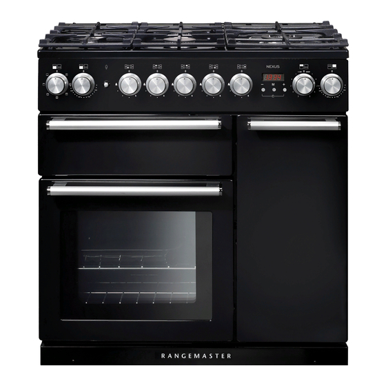
Page 7: Cooker Overview
2. Cooker Overview Fig.2.1 The 90 dual fuel cooker (Fig.2.1) has the following features: Fig.2.2 4 hotplate burners and a Wok Burner Control Panel Glide-out Grill™ with 4 position Trivet Multifunction Oven Fan Oven Hotplate Burners The labels by each of the control knobs indicates which area that knob controls. -
Page 8: Wok Burner
The igniter should spark and light the gas. Continue to press Fig.2.3 in the knob to let the gas through to the burner for about ten seconds. If and when you let go of the control knob or the burner goes out, then the FSD has not been bypassed. -
Page 9: The Griddle
The Griddle Fig.2.11 The griddle fits the left-hand pan support, front to back (Fig.2.11). It is designed for cooking food on directly. DO NOT use pans of any kind on it. The griddle surface is non-stick and metal cooking utensils (e.g. spatulas) will damage the surface. Use heat resistant plastic or wooden utensils. -
Page 10: The Glide-Out Grill
The Glide-out Grill™ Fig.2.15 Open the door and pull the grill pan carriage forward using the handle (Fig.2.15). The grill has two elements that allow either the whole area of the pan to be heated or just the right-hand half. Adjust the heat to suit by turning the control knob. -
Page 11: The Ovens
The Ovens Function The clock must be set to the time of day before the left To thaw small items in the oven without Defrost hand oven will work. See the following section on ‘The heat Clock’ for instructions on setting the time of day. A full cooking function, even heat Fan oven throughout, great for baking... -
Page 12: Multifunction Oven Functions
Multifunction Oven Functions half of the oven to cook. The oven temperature may also need to be lowered. Fan Oven Browning Element This function operates the fan and the heating element around it. An even heat is produced This function uses the element in the top of the oven throughout the oven, allowing you to cook large only. - Page 13 Operating the Ovens Fig.2.18 Operating the Multifunction Oven The multifunction oven has two controls: a function selector and a temperature setting knob (Fig.2.18). Turn the function selector control to a cooking function. Turn the oven temperature knob to the temperature required (Fig.2.18).
-
Page 14: Using The Clock
Using the Clock Fig.2.21 You can use the clock to turn the left-hand oven on and off. Note: When using the timer functions, first set the clock as required before setting the oven temperature. The oven can be switched on when the cook symbol [ ] is ArtNo.306-0001 - 3-button clock displayed. - Page 15 To Start and Then Stop the Left-hand Oven Fig.2.27 Set the left-hand oven to automatically start and stop using a combination of the ‘cook period’ and ‘stop time’. You cannot set a start time directly – this is set automatically by a combination of the ‘cook period’ and ArtNo.306-0001 - 3-button clock ‘stop time’.
-
Page 16: Accessories
Accessories Fig.2.32 Oven Shelves – Left-hand (Main) Oven Flat shelf Shelf guard In addition to the flat shelf, the cooker is supplied with a drop shelf (Fig.2.32). The drop shelf increases the possibilities for oven shelf spacing. The oven shelves can be easily removed and refitted. Front Pull the shelf forward until the back of the shelf is stopped by the shelf stop bumps in the oven sides (Fig.2.33). -
Page 17: Cooking Tips
3. Cooking Tips Tips on Cooking with the Timer General Oven Tips If you want to cook more than one dish, choose dishes that The wire shelves should always be pushed firmly to the back require approximately the same cooking time. However, of the oven. -
Page 18: Cooking Table
4. Cooking Table DocNo.031-0004 - Cooking table - electric & fan single cavity The oven control settings and cooking times given in the table below are intended to be used Top (T) AS A GUIDE ONLY. Individual tastes may require the temperature to be altered to provide a ArtNo.050-0007 preferred result. -
Page 19: Cleaning Your Cooker
ArtNo.045-0004 - Cleaning - 90 induction - tpl glzd dr & GO grill 5. Cleaning Your Cooker Essential Information Fig.5.1 Isolate the electricity supply before carrying out any thorough cleaning. Allow the cooker to cool. NEVER use paint solvents, washing soda, caustic cleaners, biological powders, bleach, chlorine based bleach cleaners, coarse abrasives or salt. -
Page 20: Grills
Grills Fig.5.5 The grill pan and trivet should be washed in hot soapy water. Alternatively, the grill pan can be washed in a dishwasher. After grilling meats or any foods that soil, leave to soak for a few minutes immediately after use. Stubborn particles may be removed from the trivet using a nylon brush. -
Page 21: Ovens
Glass Fronted Door Panels Fig.5.10 The oven door front panels can be taken off so that the glass panels can be cleaned. Move the cooker forward to gain access to the sides (see the ‘Moving the Cooker’ section under ‘Installation’). Open the oven door slightly and remove the front panel fixing screws from the door sides, two each side (Fig.5.10). -
Page 22: Cleaning Table
Cleaning Table Cleaners listed (Table 5.1) are available from supermarkets or electrical retailers as stated. For enamelled surfaces use a cleaner that is approved for use on vitreous enamel. Regular cleaning is recommended. For easier cleaning, wipe up any spillages immediately. Hotplate Part Finish... -
Page 23: Troubleshooting
6. Troubleshooting Hotplate ignition or hotplate burners faulty If there is an installation problem and I don’t get my original installer to come back to fix it who pays? Is the power on? Is the clock illuminated? You do. Service organizations will charge for their call If not, there maybe something wrong with the power outs if they are correcting work carried out by your supply. - Page 24 An oven light is not working Fig.6.1 The bulb has probably burnt out. You can buy a replacement bulb (which is not covered under the warranty) from a good electrical shop. Ask for a 15 W – ArtNo.324-0005 Oven light bulb 230 V lamp, FOR OVENS.
-
Page 25: Installation
INSTALLATION Check the appliance is electrically safe and gas sound when you have finished. 7. Installation Dear Installer In the UK the cooker must be installed in accordance with: Before you start your installation, please complete the details below, so that, if your customer has a problem relating to •... -
Page 26: Location Of Cooker
INSTALLATION Check the appliance is electrically safe and gas sound when you have finished. Location of Cooker Checking the parts: The cooker may be installed in a kitchen/kitchen diner but 3 pan supports Wok cradle NOT in a room containing a bath or shower. This appliance is designed for domestic cooking only. -
Page 27: Positioning The Cooker
INSTALLATION Check the appliance is electrically safe and gas sound when you have finished. Positioning the Cooker ArtNo.090-0009 - 90 2BC cooker min spacings Fig.7.1 Fig.7.1 and Fig.7.2 shows the minimum recommended distance from the cooker to nearby surfaces. 75 mm 75 mm 650 mm The cooker should not be placed on a base. -
Page 28: Repositioning The Cooker Following Connection
INSTALLATION Check the appliance is electrically safe and gas sound when you have finished. Lowering the Two Rear Rollers Fig.7.5 To adjust the height of the rear of the cooker, first fit a 13 mm spanner or socket wrench onto the hexagonal adjusting nut (Fig.7.5). -
Page 29: Fitting The Stability Bracket Or Chain
INSTALLATION Check the appliance is electrically safe and gas sound when you have finished. Fitting the Stability Bracket or Chain Fig.7.8 Unless otherwise stated, a cooker using a flexible gas connector must be secured with a suitable stability device. Stability chain Suitable stability devices are shown in Fig.7.8, Fig.7.9 and Fig.7.10. -
Page 30: Gas Connection
INSTALLATION Check the appliance is electrically safe and gas sound when you have finished. Gas Connection Gas inlet Fig.7.11 block This must be in accordance with the relevant standards. The flexible hose (not supplied with the cooker) must be in accordance with the relevant standards. Hoses may be purchased at most builders’... -
Page 31: Electrical Connection
INSTALLATION Check the appliance is electrically safe and gas sound when you have finished. Electrical Connection Fig.7.12 The cooker must be installed by a qualified electrician, in accordance with all relevant British Standards/Codes of Practice (in particular BS 7671), or with the relevant national and local regulations. -
Page 32: Conversion To Lp Gas
WARNING – SERVICING TO BE CARRIED OUT ONLY BY AN AUTHORISED PERSON Disconnect from electricity and gas before servicing. Check appliance is safe when you have finished. 8. Conversion to LP Gas Check the ‘Technical Data’ section at the back of the book Fig.8.1 that the hob is convertible to the gas you want to use. -
Page 33: Circuit Diagram
8. Circuit Diagram P095199 P095199 P095199 P028728 P095199 P095199 P095199 The connections shown in the circuit diagram are for single-phase. The ratings are for 230 V 50 Hz. Legende Description Description The connections shown in the circuit diagram are for single-phase. The ratings are for 230 Grill front switch Ignition switches Description... -
Page 34: Technical Data
10. Technical Data ArtNo.107-0022 - Technical data - 90DF - Classic DL, Kitchener, Professional+ THE COOKER IS CATEGORY: Cat II 2H3+. It is supplied set for group H natural gas. A conversion kit from NG to LP is available for the cooker. INSTALLER: Please leave these instructions with the User. - Page 35 Notes...
- Page 36 Notes...
- Page 37 0800 804 6261 or depending on your mobile network tariff you can call free on 0370 789 5107. For a competitive quote and to arrange for a Rangemaster approved engineer to attend, call Consumer Services on: 0800 804 6261 or...
- Page 38 Registered in England and Wales. Registration No. 354715 Registered Office: Juno Drive, Leamington Spa, Warwickshire, CV31 3RG Rangemaster continuously seeks improvements in specification, design and production of products and thus, alterations take place peri- odically. Whilst every effort is made to produce up-to-date literature, this booklet should not be regarded as an infallible guide to current...