Table of Contents
Advertisement
Quick Links
Advertisement
Table of Contents

Related Manuals for NCR RealPOS 72XRT POS


Summary of Contents for NCR RealPOS 72XRT POS
- Page 1 USER GUIDE POS (7616) NCR RealPOS 72 Release 1.1 B005-0000-2228 Issue C...
- Page 2 NCR, therefore, reserves the right to change specifications without prior notice. All features, functions, and operations described herein may not be marketed by NCR in all parts of the world. In some instances, photographs are of equipment prototypes. Therefore, before using this document, consult with your NCR representative or NCR office for information that is applicable and current.
- Page 3 Audience This book is written for hardware installer/service personnel, system integrators, and field engineers. Notice: This document is NCR proprietary information and is not to be disclosed or reproduced without consent. Safety Requirements The NCR RealPOS 72XRT conforms to all applicable legal requirements. To view the compliance statements see the NCR RealPOS Terminals Safety and Regulatory Statements (B005-0000-1589).
- Page 4 This terminal should only be used with peripheral devices that are certified by the appropriate safety agency for the country of installation (UL, CSA, TUV, VDE) or those which are recommended by NCR Corporation. Warning: DO NOT connect or disconnect the transaction printer while the terminal is connected to AC power.
- Page 5 If you do not have access to a computer, you may leave a voice message at: 1-800-528- 8658 (USA), or (International) +1-770-623-7400. When leaving a message, please provide a phone number and/or an email address so NCR can contact you if additional details are needed.
- Page 6 • Description of the problem, including any system error codes, error condition, or guidance to the area of failure. The NCR Agent will provide you with a work order number, which serves as your Return Material Authorization (RMA). Please provide the RMA on the outside of the shipping box.
-
Page 7: Table Of Contents
Table of Contents Chapter 1: Product Overview Introduction Product IDs Terminal Dimensions and Weights Configurations GMS Integration Tray Kit (7403-K300) Hospitality Integration Tray Kit (7403-K301) Integrated Customer Displays Display Wall Mount (7403-K321) Model and Serial Number Labels Features Key Features Processor Motherboard Memory... - Page 8 ACPI States for Windows Enabling Wake on LAN Windows 7 Windows XP Remote Customer Displays NCR 5976 2x20 LCD Customer Display Character Sets NCR RealPOS 5943 12.1-Inch LCD NCR RealPOS 5943 15-Inch LCD NCR RealPOS 5967 12.1-Inch Touch LCD NCR RealPOS 5967 15-Inch Touch LCD NCR 5982 6.5-Inch LCD Display...
- Page 9 Powering Up the Terminal Terminal On/Off Switch Power Button Override Default Boot Order Keyboard support Connecting peripherals Calibrating the Touch Screen Out-of-Box Failures Chapter 3: POST Diagnostics Diagnostic LEDs Beep Codes Boot Block Beep Codes POST BIOS Beep Codes Chapter 4: Touch Screen Calibration Introduction Installing the Driver Touch Methods...
- Page 10 Powered USB Cable Connections NCR RealPOS 5943 15-inch LCD Cable Connections VGA Connections Powered USB Cable Connections NCR RealPOS 5967 12-inch Touch LCD Cable Connections VGA Connections Powered USB Cable Connections NCR RealPOS 5967 15-inch Touch LCD Cable Connections VGA Connections...
- Page 11 Cursor Position (10h, POSITION) Reset (13h) Character Tables and Codes CP437 CP858 CP866 CP932 Chapter 10: BIOS Setup Entering Setup How to Select Menu Options Restoring Factory Settings Disabling Resources Keyboard Shortcuts BIOS Default Values Main Menu Advanced Menu Chipset Menu Boot Menu Chapter 11: BIOS Updating Procedure Introduction...
- Page 12 Installation Starting the Intel SSD Toolbox Manually Running the Intel® SSD Optimizer Scheduling the Intel® SSD Optimizer Removing a Scheduled Intel® SSD Optimizer Session Additional Information Known Limitations Known Issues Chapter 14: Touch Screen Operation Introduction Touch Mode of Operation Changing the Touch Mode Turning Off the Mouse Pointer Terminal Placement...
-
Page 13: Chapter 1: Product Overview
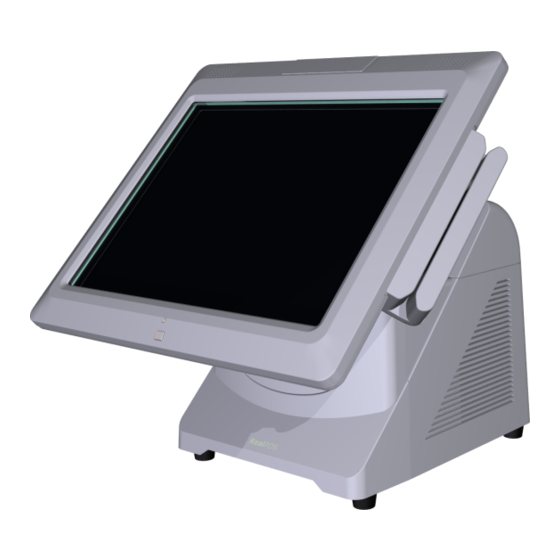
The terminal has been enhanced to offer even better serviceability and scalability than previous generations. Engineered to thrive in the most demanding environments, the NCR RealPOS 72 offers retailers in Hospitality, Convenience Stores, and General Merchandise a POS platform that offers exceptional value for their POS investment. -
Page 14: Configurations
Product Overview Configurations There are field upgradeable kits for the NCR RealPOS 72 that provide for many configuration variations. This section illustrates each of these and lists the associated kits. GMS Integration Tray Kit (7403-K300) This kit provides the necessary components for integrating a printer and keyboard with the NCR RealPOS 72 terminal for a General Merchandise environment. -
Page 15: Hospitality Integration Tray Kit (7403-K301)
Product Overview Hospitality Integration Tray Kit (7403-K301) This kit provides the necessary components for integrating a printer with the NCR RealPOS 72 terminal for a Hospitality environment. It can be mounted on a flat surface or on a cash drawer. -
Page 16: Integrated Customer Displays
Product Overview Integrated Customer Displays There are various kits that are used for integrating VFD and LCD customer displays on the back of the NCR RealPOS 72 terminal. • 7403-K451: Integrated 2x20 Customer Display • 7403-K452: Rear Consumer Display Pole Mount (for 5975 Display) •... - Page 17 Product Overview There are four post options for the 5975 display, available in 4 inch increments...
-
Page 18: Display Wall Mount (7403-K321)
Product Overview Display Wall Mount (7403-K321) This kit is used in to install a 7616 Display Head remotely on a vertical surface. -
Page 19: Model And Serial Number Labels
Product Overview Model and Serial Number Labels The serial number and model number labels located on the back of the Display Head, on the top back edge of the Display Head, and on the bottom of the Base. If the terminal was shipped with an Operating System pre-installed then there is also a Certificate of Authenticity label on the bottom of the Base. -
Page 20: Features
Product Overview Features Key Features • Extreme performance with Intel® Core™ processor family • Fast and reliable capacitive touch screen with full-tilt capability • Integrated compact design with customizable customer-facing display system • Reduced power consumption with energy-efficient Intel processor technology and high-efficiency 80 PLUS power supply •... -
Page 21: Connectivity
The terminal has a protection diode on board to limit back EMF from the solenoid when the solenoid turns off. Third party cash drawers should also have a diode installed across the solenoid to further reduce potentially damaging overshoot from the solenoid. This diode is present on all NCR cash drawers. -
Page 22: Display
1-10 Product Overview Display • 15” capacitive touchscreen • 17” capacitive touchscreen • High-brightness LCD • Full-tilt capability (0˚ - 90˚) • Integrated stereo speakers • Motion sensor Display Options • Integrated 3-track ISO MSR • Integrated biometric fingerprint reader Consumer Display Options •... - Page 23 Product Overview 1-11 • Lighted Logo to Indicate Power On / Suspend Mode • LAN Link Activity • Hard Drive Activity • Six Diagnostic LEDs...
-
Page 24: Base Model Comparison
1-12 Product Overview Base Model Comparison Performance Extreme Model RealPOS 72XRT Base (Class 7616) Standard Model 1200 Model 1300 1500 Processor Celeron G530T Core i3-2120T Core i5-2390T Clock Speed 2Ghz 2.6GHz 2.7GHz Cache CPU Cores Chipset Intel Q67 express Thermal Design Power 35 Watts AMT 8 * Memory... - Page 25 Product Overview 1-13 Performance Extreme Model RealPOS 72XRT Base (Class 7616) Standard Model 1200 Model 1300 1500 USB, 5V (dedicated – rear consumer 1(consumer touch display) display system) Dual Independent Display Support Standard Video Interface – Consumer 1 – VGA(supports Hi-definition) Ethernet LAN 10/100/1000Mb Cash Drawer Ports...
-
Page 26: Msr
ISO format cards. The MSR is by default an OPOS device but can be reprogrammed for use with keyboard stream applications. Note: See the NCR MSR Configuration User Guide (B005-0000-2031) Issue D (or later) for details on how to configure the MSR for keyboard stream applications. -
Page 27: Rear Signage
Product Overview 1-15 Rear Signage Customer provided signage information (7.25" x 5.5") can be displayed on the back of the 7616. Plastic covers are required to hold the sign in place. The Signage Kit (7403-K455) contains 5 plastic inserts for this purpose. -
Page 28: Port Security
1-16 Product Overview Port Security The NCR RealPOS 72 provides communication port security by protecting all connections via a key lock or a cover requiring tools to open. This keeps the terminal safe from users that might try to remove data or inject a virus via a USB port or other connection. -
Page 29: I/O Board
Product Overview 1-17 I/O Board The I/O Board is used to provide external connections for the motherboard. It slides into position in the terminal below the motherboard. -
Page 30: I/O Board Connectors
1-18 Product Overview I/O Board Connectors • Ethernet • One 10/100/1000 MDI port • USB • Four High Speed Ports. Each port is capable of supplying 5 V at 0.5 A max. Self healing polyfuses are used to provide current protection. •... - Page 31 Product Overview 1-19 Additional peripheral connectors are located under the Customer Display.
-
Page 32: Power Management
1-20 Product Overview Power Management Power management is implemented on the 7616 terminal using the Advanced Configuration and Power Interface (ACPI) 3.0b specification. A key feature of ACPI is that the operating system, not the BIOS, configures and implements power management. -
Page 33: G0 Working
S1 sleeping state except that the CPU and system cache context is lost (the OS is responsible for maintaining the caches and CPU context). Control starts from the processor's reset vector after the wake event. In NCR systems, during S3, power is only provided to the on-board USB ports. - Page 34 1-22 Product Overview Requirements for S4 support: • O/S must be built on a system with S3 enabled in the BIOS • Some peripherals may not be S4 capable, which can prevent the system from entering S4 state. • S5 (Unit OFF) Reference the ACPI Specification for details.
-
Page 35: Acpi States For Windows
Product Overview 1-23 ACPI States for Windows **S3 Suspend **S5Soft S0Working S1Standby S4Hibernate Power State to RAM Supported: Y / N Description Fully • Video Back • Video Back • Video Back Functional Light Off Light Off Light Off • HDD Off •... -
Page 36: Enabling Wake On Lan
1-24 Product Overview Enabling Wake on LAN In order for Wake on LAN to function the Network driver must be enabled (factory default). The procedure for enabling the driver depends on which operating system you are using. Windows 7 1. Select Start Computer System... - Page 37 Product Overview 1-25 2. Expand Network adapters and then Right-mouse click the Intel(R) 82567V Gigabit Network Connection driver. Select Properties.
- Page 38 1-26 Product Overview 3. Under the Power Management tab the Wake on Magic Packet and Wake on Magic Packet from power off state option boxes should be checked as shown below. Select after making any changes.
-
Page 39: Windows Xp
Product Overview 1-27 Windows XP 1. Select Start Control Panel Hardware Tab → Device Manager button. → →... - Page 40 1-28 Product Overview 2. Select Network adapters and then Right-mouse click Intel(R) 82567V Gigabit Network Connection and select Properties.
- Page 41 Product Overview 1-29 3. Under the Power Management tab the option boxes as shown below should be checked. Select after making any changes.
-
Page 42: Remote Customer Displays
Remote Customer Displays NCR 5976 2x20 LCD Customer Display The NCR RealPOS 5976-1xxx Customer Display is a 2-line x 20-character LED backlit Liquid Crystal Display (LCD), which can display any downloadable codepage of single byte characters. It supports both RS-232 and USB interfaces. -
Page 43: Character Sets
• Table Mount, 4-in. Post • Table Mount, 8-in. Post • Table Mount, 12-in. Post • Table Mount, 16-in. Post • Integrated Mount for NCR 7456, 7457, 7458 Character Sets • Support for 19 character sets • 3 Character sets in base unit •... -
Page 44: Ncr Realpos 5943 12.1-Inch Lcd
Product Overview NCR RealPOS 5943 12.1-Inch LCD The NCR 5943 LCD is an LED backlit LCD display (XGA, 1024 x 768). The display is powered by the terminal from a +12V USB Plus Power port. The remote mount must be ordered separately. -
Page 45: Ncr Realpos 5943 15-Inch Lcd
1-33 NCR RealPOS 5943 15-Inch LCD The NCR 5943 LCD is an LED backlit LCD display (XGA, 1024 x 768). The display is powered by the terminal from a +12V USB Plus Power port. The remote mount must be ordered separately. -
Page 46: Ncr Realpos 5967 12.1-Inch Touch Lcd
Product Overview NCR RealPOS 5967 12.1-Inch Touch LCD The NCR 5967 Touch LCD is an LED backlit LCD display (XGA, 1024 x 768) with capacitive touch screen. The display is powered by the terminal from a +12V USB Plus Power port. The remote mount must be ordered separately. -
Page 47: Ncr Realpos 5967 15-Inch Touch Lcd
1-35 NCR RealPOS 5967 15-Inch Touch LCD The NCR 5967 Touch LCD is an LED backlit LCD display (XGA, 1024 x 768) with capacitive touch screen. The display is powered by the terminal from a +12V USB Plus Power port. The remote mount must be ordered separately. -
Page 48: Ncr 5982 6.5-Inch Lcd Display
1-36 Product Overview NCR 5982 6.5-Inch LCD Display The NCR 5982 LCD Display is a terminal-powered color 6.5-Inch VGA LCD. Features • 5-inch VGA Monochrome LCD (640 x 480 VGA) • Contrast Control • LED Back Light • Keyboard Mount •... -
Page 49: Transaction Printers
Transaction Printers NCR RealPOS 7167 Printer The NCR 7167 Printer is a fast, quiet, relatively small and very reliable multi function printer. It prints receipts, validates and prints checks, and prints on a variety of single or multiple part forms. There is not journal as it is kept electronically by the host terminal. -
Page 50: Ncr Realpos 7168 Printer
Product Overview NCR RealPOS 7168 Printer The NCR 7168 Printer is a fast, quiet, relatively small and very reliable multiple-function printer with front and back printing on the receipt paper capability. It prints receipts, validates and prints checks, and prints on a variety of single- or multiple-part forms. -
Page 51: Ncr Realpos 7198 2St Printer
1-39 NCR RealPOS 7198 2ST Printer The NCR 7198 Printer is a fast, quiet, relatively small and very reliable printer with front and back printing on the receipt paper capability. The printer can connect through a USB port or a serial port. It can receive power from a power supply or through a USB+ power cable. - Page 52 1-40...
-
Page 53: Chapter 2: Installing The Terminal
Kit Instructions for each. They can be downloaded from the Retail IP Web Sites: Internet: • http://www.info.ncr.com http://inforetail.ncr.com • NCR Intranet: To locate the installation guides on these sites: 1. Select General Search. 2. Select the Kit Instructions icon. -
Page 54: Installation Summary
Installation Restrictions "Before installing the terminal, read and follow the guidelines in the NCR RealPOS 72 Site Preparation Guide (B005 0000 2229) and the NCR Workstation and Peripheral AC Wiring Guide (BST0 2115 53). -
Page 55: Connecting The External Cables
Installing the Terminal 2-43 Connecting the External Cables Most external cables connect to the I/O Panel and route under the terminal, which is located behind the Front Base Cover. Others connect to the Backplane Board and are routed out the Base Rear Cover. This section shows how to gain access to the connectors and how to secure the cables. -
Page 56: Accessing The I/O Panel
2-44 Installing the Terminal Accessing the I/O Panel 1. Tilt the Display Module. 2. Remove the Front Base Cover. a. Insert the Security Key and turn it 90 degrees clockwise. - Page 57 Installing the Terminal 2-45 b. Pivot the top of the Front Base Cover toward the front of the unit and remove it from the terminal.
-
Page 58: Powered Serial Port Jumper Settings And Fuses
2-46 Installing the Terminal Powered Serial Port Jumper Settings and Fuses The four serial ports have jumper options for either Ring Indicator (RI), fused +12 V, or fused +5 V on pin 9. When set to powered each port is capable of supporting up to 1.5 A (Max.) and is protected with self-healing Poly-Fuse. -
Page 59: Accessing The Backplane Connectors
Installing the Terminal 2-47 Accessing the Backplane Connectors 1. Remove the screws (2) from the rear of the unit. 2. Loosen the Captive Screws (2) and remove the Remote Display Base. -
Page 60: Ac Power Cord Connection
2-48 Installing the Terminal AC Power Cord Connection 1. Connect the Power Cord to the system and to an AC power source. 2. Secure the cable in the Cable Clamp. -
Page 61: Cable Routing
Installing the Terminal 2-49 Cable Routing The cables from the I/O Board are routed under the base and out the bottom of the unit. Cables from the Backplane Board are routed out an opening in the Cover and down the back of the terminal. -
Page 62: Cable Routing From The I/O Board
2-50 Installing the Terminal Cable Routing from the I/O Board There are two ways to secure the cables from the I/O Board. • With DVD-ROM Drive • Without DVD-ROM Drive Terminal Configured with a DVD-ROM Drive If configured with a DVD the cables are routed in the two channels in the bottom of the Base. -
Page 63: Terminal Without A Dvd-Rom Drive
Installing the Terminal 2-51 Terminal without a DVD-ROM Drive If there is no DVD present then there is a Cable Clamp on the front of the Base chassis that is used to secure the cables. 1. Loosen the Cable Clamp Thumbscrew 2. - Page 64 2-52 Installing the Terminal 3. Route the cable between the clamp and base. 4. Route the cables in the two channels in the bottom of the Base (as shown on the previous page) and secure them with Tie Wraps as necessary. 5.
-
Page 65: Cable Routing From The Backplane Board
Installing the Terminal 2-53 Cable Routing from the Backplane Board 1. Remove the Remote Display Base 2. Connect the cable(s) to the Backplane Board. 3. Route the cable(s) through the opening in the rear of the cabinet and down the back of the terminal to the peripheral device. -
Page 66: Optional Vga Extension Cable
2-54 Installing the Terminal Optional VGA Extension Cable There is an optional short VGA Extension Cable that can be used to provide a VGA connection from the Backplane Board to the front of the terminal. 1. Remove the Remote Display Base. 2. - Page 67 Installing the Terminal 2-55 3. Connect the VGA Extension Cable to the Backplane Board. 4. Route the cable down the back and then under the terminal to the front. 5. Locate the end of the cable in the area of the I/O Board connectors.
-
Page 68: Removing The Storage Media
2-56 Installing the Terminal Removing the Storage Media Squeeze the latch on the green Storage Media Bracket and pull the assembly out of the chassis, which also disconnects it from the Backplane Board. There are three Storage Media options available for the 7616. Some devices are a large format (3.5") and some are a small format (2.5"). -
Page 69: Powering Up The Terminal
Installing the Terminal 2-57 Powering Up the Terminal Terminal On/Off Switch The Terminal On/Off Switch is located on the Front Base Cover. This is a logic switch only and does not remove power to the system. After AC power is applied, it can take several seconds for the unit to respond when the Terminal On/Off Switch is pressed. -
Page 70: Default Boot Order
Third-Party Product website http://www.rsg.ncr.com/tpp/ Keyboard support The RealPOS 72 does not support legacy NCR keyboards and DynaKeys that require PS/2 connections. USB keyboards are supported Connecting peripherals All peripheral ports are color-coded and labeled. All feature self-healing fuses. If they become shorted functionality is restored when the terminal is rebooted. -
Page 71: Out-Of-Box Failures
During installation if there is an Out of Box failure, the defective component will be replaced. The defective part number must be identified by trained service personnel. If required, contact your Equipment Provider, NCR Customer Service or your Service Provider to diagnose the failure to the component level. - Page 72 2-60...
-
Page 73: Chapter 3: Post Diagnostics
POST Diagnostics Chapter 3: Diagnostic LEDs The system power switch and a series of Diagnostic and Status LEDS are visible on the Front Base Cover. - Page 74 3-62 POST Diagnostics • Power Status LED - This White LED is used to illuminate the NCR Logo on the bezel to indicate that the system is on. In addition, this LED blinks when the system is in S3 suspend mode.
-
Page 75: Beep Codes
POST Diagnostics 3-63 Beep Codes Boot Block Beep Codes Number of Description Beeps No media present. (Insert diskette in floppy drive A:) 'AMIBOOT.ROM' file not found in root directory of diskette in A: Insert next diskette if multiple diskettes are used for recovery Flash Programming successful File read error No Flash EPROM detected... - Page 76 3-64 POST Diagnostics Troubleshooting POST BIOS Beep Codes Number Troubleshooting Action Beeps 1, 3 Reseat the memory, or replace with known good modules. 6, 7 Fatal error indicating a serious problem with the system. Before declaring the motherboard beyond all hope, eliminate the possibility of interference by a malfunctioning add-in card.
-
Page 77: Chapter 4: Touch Screen Calibration
• A keyboard may be required to start the calibration if the screen is too much out of calibration. However, most of the time you can reach the Start button or Touch icon with your fingertip/stylus. • The latest calibration software can be downloaded from the NCR website. http://www.ncr.com 1. At this site, select the Support tab. -
Page 78: Installing The Driver
4-66 Touch Screen Calibration Installing the Driver Note: If you have a previous version of another touch screen driver loaded on your system you must completely remove it using the Control Panel Add/Remove program before continuing with this installation process. 1. -
Page 79: Touch Methods
Touch Screen Calibration 4-67 Touch Methods Before performing the calibration procedure please observe the following guidelines for proper/improper methods of touching the screen. • Face the monitor directly. • Perform the calibration in the position (sitting or standing) that you normally expect to use the touch screen. - Page 80 4-68 Touch Screen Calibration • Do NOT touch the display or bezel with your other hand. • Do NOT get your body too close to the display.
- Page 81 Touch Screen Calibration 4-69 • Do NOT touch the bezel with your other fingers. • Do NOT spread your other fingers near the touch-screen surface.
- Page 82 4-70 Touch Screen Calibration • Do NOT get your hand and other fingers too close to the bezel.
-
Page 83: Calibration Procedures
Touch Screen Calibration 4-71 Calibration Procedures Note: In order to achieve an accurate calibration the touch display must in the normal operating position when AC power is applied to the terminal (45 degrees can be assumed if this not known). If this was NOT done properly then begin with Step 1. Otherwise skip to Step 2. - Page 84 4-72 Touch Screen Calibration 5. Touch the center of the target. Pull your finger a few inches away from the screen when you see the Release message. 6. Repeat the process for each target location as they appear. 7. After all targets have been touched a test screen displays. Touch the screen in various locations to verify the calibration results.
- Page 85 Touch Screen Calibration 4-73 8. After touching Accept you are warned to not touch the screen. Caution: Touching the screen during this time can cause the application to hang. This screen automatically closes after the touch controller has completed communicating. When complete, the system returns to the desktop with the TSHARC Control Panel displayed.
-
Page 86: Verifying The Calibration
4-74 Touch Screen Calibration Verifying the Calibration 1. Select the Tools tab. 2. Select the DrawingTest button. 3. Test the calibration on the draw screen. Touch the screen in various spots and trace each of the horizontal and vertical lines, including the border around the screen. -
Page 87: Optional Settings
Touch Screen Calibration 4-75 Optional Settings After the touch screen is calibrated, adjust the other features to meet your personal preferences. • Double-Click Option • Right-Mouse Click • Touch Modes • Touch Sounds 1. Touch the center of the target. Pull your finger a few inches away from the screen when you see the Release message. - Page 88 4-76 Touch Screen Calibration 3. After all targets have been touched a test screen displays. Touch the screen in various locations to verify the calibration results. Select Accept if you are satisfied with the results. If not, select Cancel and repeat the process. Note: Do not touch ESC to exit from this screen.
-
Page 89: Chapter 5: Configuring A Secondary Display
Configuring a Secondary Display Chapter 5: Introduction The Motherboard uses an integrated video controller. This controller provides a Notebook port (Primary LCD) and a Monitor port (VGA) on the Backplane connector row. These two ports can provide either a single display mode (Notebook or Monitor) or a dual display mode (Notebook and Monitor). -
Page 90: Setting The Display Mode
5-78 Configuring a Secondary Display Setting the Display Mode Note: Use this procedure for configuring displays that are connected to the Motherboard ports. The dual mode is configured with the Intel® Graphics and Media Control Panel. Right- click the Desktop. From the menu select Graphics Properties to display the panel. - Page 91 Configuring a Secondary Display 5-79 3. Select the display Configuration Mode Configuration Description Mode Single Display Single display (even if two displays are connected) Clone Displays Drives both displays with the same video content. Extended Drives the both displays with the desktop that spans from one display Desktop onto the other.
-
Page 92: Intel Graphics Controller Hot Keys
5-80 Configuring a Secondary Display 5. Select within 15 seconds to accept the new settings. Applications may behave differently in a multi-monitor configuration depending on their implementation: • Standard Windows applications that use the GDI (Graphics Device Interface) will clip the window to each display and accelerate the images separately using the display hardware. -
Page 93: Chapter 6: Configuring Amt
Configuring AMT Chapter 6: This chapter explains how to configure an NCR RealPOS 72 so it can be accessed remotely using Intel Management Technology (AMT). Configuring the Terminal 1. Re-boot the terminal. 2. When you see the message Press DEL to enter setup... - Page 94 6-82 Configuring AMT 3. Under the Advanced tab, select AMT Configuration and press [Enter]. Aptio Setup Utility - Copyright (C) 2011 American Megatrends, Inc. Main Advanced Chipset Boot Security Save & Exit AMT Parameters Legacy OpROM Support [Enabled] Network PXE Loading [Enabled] Mass Storage Option ROM Loading ►...
- Page 95 F10: Save and Exit ESC/Right Click: Exit 5. Press [Enter] to Save and Exit. 6. During re-boot watch for the following message: Press <CTRL-P> to enter Intel(R)ME Setup 7. This message occurs immediately after the NCR logo disappears. At that moment, press Ctrl-P.
- Page 96 9. Enter the new password (write it down to remember). The password must contain upper, lower, symbol, & numeric characters. Example: Ncr@2011 You must enter the password a second time for verification. Intel (R) Management Engine BIOS Extension v7.0.0.0056/Intel(R) ME v7.1.20.1119 Copyright (C) 2003-11 Intel Corporation.
- Page 97 Configuring AMT 6-85 Highlight Intel(R) Standard Manageability Configuration and press [Enter] Intel (R) Management Engine BIOS Extension v7.0.0.0056/Intel(R) ME v7.1.20.1119 Copyright (C) 2003-11 Intel Corporation. All Rights Reserved MAIN MENU ====================[ ]==================== Intel(R) ME General Settings ► Intel(R) Standard Manageability Configuration ► Exit ============================================================= [ESC]=Exit---------- [↑↓]=Select---------- [ENTER]=Access...
- Page 98 6-86 Configuring AMT Enter to activate the network interface. Intel (R) Management Engine BIOS Extension v7.0.0.0056/Intel(R) ME v7.1.20.1119 Copyright (C) 2003-11 Intel Corporation. All Rights Reserved ====================[MAIN MENU ]===================== Manageability Feature Selection SOL/IDER User Consent Password Policy Network Setup Activate Network Access Unconfigure Network Access Remote Setup and Configuration =============================================================...
-
Page 99: Logging Onto The Terminal Using Amt
Configuring AMT 6-87 Logging onto the Terminal Using AMT After configuring the 7616 you should now be able to log into it from a browser on a remote PC. 1. Determine the target terminal's IP address. Windows: Start → All Programs → Accessories → Command Prompt Enter ipconfig and press [Enter]. - Page 100 6-88 Configuring AMT 5. Enter the UserName and Password and then select OK. UserName: admin Password: <[your password]>...
- Page 101 Configuring AMT 6-89 The System Status Screen is displayed. You can now control the AMT functions.
-
Page 102: Function Definitions
Hardware Information System Displays the DMI for Type 0,1, and 2 (BIOS info - Class/model/serial). If NCR tools are used to flash the BIOS the NCR BIOS version and MAC addresses are displayed. Processor Displays the CPU information from DMI. -
Page 103: Removing The Hard Disks
Configuring AMT 6-91 Remote Control Used to perform immediate power down, reset, or power cycle off/on. Caution: This function is non-OS awareness, which can result in OS corruption. Also, the power loss can cause the AMT connection to be broken. Power Policies Used to change the Power Policy remotely. - Page 104 6-92...
-
Page 105: Chapter 7: Installing Optional Remote Peripherals
Installing Optional Remote Peripherals Chapter 7: Introduction This chapter discusses how to install optional remote peripheral devices. Cable Routing Peripheral cables connect to the I/O Panel behind the Base Front Cover or to the Backplane Board. See the Connecting the External Cables section in the Installing the Terminal chapter for instructions how to access the connectors and how to route the cables. -
Page 106: Installing A Transaction Printer
7-94 Installing Optional Remote Peripherals Installing a Transaction Printer Note: This section discusses how to connect a remote printer. The printers can also be integrated with the 7616 terminal using the Integration Trays. See the GMS Integration Tray (7616-K300) or Hospitality Integration Tray (7616-K301) Kit Installations for more information. -
Page 107: Rs-232 Installation W/Power From Powered Usb
Installing Optional Remote Peripherals 7-95 RS-232 Installation w/Power from Powered USB 1. Connect the RS-232 Printer Interface Cable to the RS-232 connector on the printer and to an RS-232 connector on the terminal. 2. Connect the Printer Power Cable to the Power connector on the printer and to the 24 V Powered USB connector on the terminal. -
Page 108: Installing A Remote Customer Display
7-96 Installing Optional Remote Peripherals Installing a Remote Customer Display The Standard Remote Mount (5964-K031) is used to mount the following NCR displays. • NCR RealPOS 5943 12.1-Inch Monitor • NCR RealPOS 5943 15-Inch Monitor • NCR RealPOS 5967 12.1-Inch Touch Monitor •... - Page 109 Installing Optional Remote Peripherals 7-97 2. Route the cable(s) down through the mount and out the back of the base. 3. Connect the cable to the proper connector on the host terminal.
-
Page 110: Ncr Realpos 5943 12-Inch Lcd Cable Connections
7-98 Installing Optional Remote Peripherals NCR RealPOS 5943 12-inch LCD Cable Connections The following illustrations show the cable connections for the 5943 LCD and the 7616 terminal. There are two cables required. • VGA cable for video • Powered Universal Serial Bus (USB) for data and power... -
Page 111: Vga Connections
Installing Optional Remote Peripherals 7-99 VGA Connections Connect the LCD Cable to the VGA connectors on both the 5943 LCD and 7616 terminal. -
Page 112: Powered Usb Cable Connections
Powered USB Cable Connections Connect the Powered USB Cable to the 5943 LCD and to one of the 12V Powered USB connectors on the 7616 terminal. For more information refer to the NCR RealPOS 5943 12-Inch LCD User's Guide (B005-- 0000-2043) -
Page 113: Ncr Realpos 5943 15-Inch Lcd Cable Connections
Installing Optional Remote Peripherals 7-101 NCR RealPOS 5943 15-inch LCD Cable Connections The following illustrations show the cable connections for the 5943 LCD and the 7616 terminal. There are two cables required. • VGA cable for video • Powered Universal Serial Bus (USB) for data and power... -
Page 114: Vga Connections
7-102 Installing Optional Remote Peripherals VGA Connections Connect the LCD Cable to the VGA connectors on both the 5943 LCD and 7616 terminal. -
Page 115: Powered Usb Cable Connections
Powered USB Cable Connections Connect the Powered USB Cable to the 5943 LCD and to one of the 12V Powered USB connectors on the 7616 terminal. For more information refer to the NCR RealPOS 5943 15-Inch LCD User's Guide (B005- 0000-2182). -
Page 116: Ncr Realpos 5967 12-Inch Touch Lcd Cable Connections
7-104 Installing Optional Remote Peripherals NCR RealPOS 5967 12-inch Touch LCD Cable Connections The following illustrations show the cable connections for the 5967 LCD and the 7616 terminal. There are two cables required. • VGA cable for video • Powered Universal Serial Bus (USB) for data and power... -
Page 117: Vga Connections
Installing Optional Remote Peripherals 7-105 VGA Connections Connect the LCD Cable to the VGA connectors on both the 5967 LCD and 7616 terminal. -
Page 118: Powered Usb Cable Connections
Powered USB Cable Connections Connect the Powered USB Cable to the 5967 LCD and to one of the 12V Powered USB connectors on the 7616 terminal. For more information refer to the NCR RealPOS 5943 12-Inch Touch LCD User's Guide (B005--0000-2045). -
Page 119: Ncr Realpos 5967 15-Inch Touch Lcd Cable Connections
Installing Optional Remote Peripherals 7-107 NCR RealPOS 5967 15-inch Touch LCD Cable Connections The following illustrations show the cable connections for the 5967 LCD and the 7616 terminal. There are two cables required. • VGA cable for video • Powered Universal Serial Bus (USB) for data and power... -
Page 120: Vga Connections
7-108 Installing Optional Remote Peripherals VGA Connections Connect the LCD Cable to the VGA connectors on both the 5967 LCD and 7616 terminal. -
Page 121: Powered Usb Cable Connections
Powered USB Cable Connections Connect the Powered USB Cable to the 5967 LCD and to one of the 12V Powered USB connectors on the 7616 terminal. For more information refer to the NCR RealPOS 5943 15-Inch Touch LCD User's Guide (B005-0000-2193). -
Page 122: Installing An Ncr 5975/5976 Remote Customer Display
7-110 Installing Optional Remote Peripherals Installing an NCR 5975/5976 Remote Customer Display There are two models of the NCR 5975/5976 Remote Customer Displays: • 5976-1xxx - 2x20 VFD • 5975-2xxx - Graphical VFD... - Page 123 Installing Optional Remote Peripherals 7-111 There are four different length posts available, in four inch increments. 1. Locate the Display Mount within 4 meters (13 ft.) of the host terminal. 2. Determine if the cable should be routed down through the mounting surface or if it should be run on top of the surface.
- Page 124 7-112 Installing Optional Remote Peripherals a. Remove the screws (2) from the Display Back. b. Remove the Display Back. c. Route the Interface Cable though the opening in the Display Back. d. Connect the cable to the proper connector on the Display Module. e.
- Page 125 Installing Optional Remote Peripherals 7-113 5. Route the Interface Cable through the Post and assemble the Post components. 6. Connect the Display Cable to the terminal, based on the type of interface you are using.
-
Page 126: Usb Interface (Powered)
Connect the I/F cable to a powered RS-232 connector on the terminal. Note: The factory settings for the COM ports are non-powered by default. To change a port to powered see the Circuit Boards chapter in the NCR RealPOS 72 Service Guide, B005-0000-2230. -
Page 127: Installing A Cash Drawer
Installing Optional Remote Peripherals 7-115 Installing a Cash Drawer The Cash Drawer can be connected to the Cash Drawer connector or to the transaction printer. -
Page 128: Installing A Second Cash Drawer
7-116 Installing Optional Remote Peripherals Installing a Second Cash Drawer The terminal also supports a 2-drawer configuration using a Y-cable (1416-C372-0006) connected to terminal or to the printer. 1. Place the cash drawer in the desired location, within cable's length of the printer. 2. -
Page 129: Chapter 8: Configuring A Second Hdd For Raid
Configuring a Second HDD for RAID Chapter 8: Introduction This chapter discusses how to add a second hard drive and configure a RAID system using the Intel® Rapid Storage Technology. Note: For information about how to install disk images on a system that is already configured as a RAID system see the Installing Disk Images on a RAID System chapter. -
Page 130: Installation Procedures
Configuring a Second HDD for RAID Installation Procedures 1. Install the primary HDD. 2. Load the NCR Gold Drive. 3. Install the second hard disk drive in the terminal (hot plug). 4. Run the Intel® Rapid Storage Technology Manager. Start... - Page 131 Configuring a Second HDD for RAID 8-119 6. Select the type of RAID volume you want to install. NCR supports RAID 1 and RAID 0 volume types. RAID 1: Combines two disks to create a volume where each disk stores an exact copy of the data and provides real-time redundancy.
- Page 132 8-120 Configuring a Second HDD for RAID 8. Enter a Volume Name (user preference). 9. Select the check boxes for both disks. RAID 0 Only: Specify the amount of space to be used by the new RAID volume. Use the slider to enter a percentage. Note: If you create a volume that uses less than 100% of the hard drive space, you may create a second RAID volume to use the remaining space.
- Page 133 Configuring a Second HDD for RAID 8-121 10. Select Next. 11. Select Create Volume to start the volume migration. 12. Select to confirm the action.
- Page 134 8-122 Configuring a Second HDD for RAID 13. A window is displayed indicating the volume was created successfully. Select close the window. The status of the migration is displayed, showing the progress. This can take 1 - 3 hours to complete.
-
Page 135: Replacing A Failed Raid 1 (Mirrored) Hdd
Configuring a Second HDD for RAID 8-123 Replacing a Failed RAID 1 (Mirrored) HDD If a hard drives fails there is no indication except for a RAID volume status that is displayed during boot. This may be a Failed, Degraded, or Rebuild status. You are advised to press CTRL-I to enter the Configuration Utility to correct the condition. -
Page 136: Failed Disk Replacement Procedure
8-124 Configuring a Second HDD for RAID Failed Disk Replacement Procedure 1. Replace the defective HDD (hot plug). 2. Run the Intel® Rapid Storage Technology Manager. Start All Programs Intel Intel® Rapid Storage Technology → → → 3. The Status screen indicates the failed disk. Select Rebuild to another disk. - Page 137 Configuring a Second HDD for RAID 8-125 5. The status of the disk rebuild is displayed, showing the progress. This can take 1 - 3 hours to complete.
- Page 138 8-126...
-
Page 139: Chapter 9: 2X20 Customer Display Interface
2x20 Customer Display Interface Chapter 9: Introduction The 2x20 Customer Display consists of a Vacuum Florescent Display (VFD) with two rows of twenty 5x8 dot matrix characters, an RS-232 serial interface, driver circuitry, DC to DC/AC converter, and a character generator. General Specifications Item Value... -
Page 140: Command Codes
9-128 2x20 Customer Display Interface Command Codes User Defined Character Definition (08h, CODE, Byte1…Byte5) This command defines a user defined character (UDC). The UDC character code is set by the CODE byte and must be 00H to 07H. All other values for CODE will be ignored by this command. -
Page 141: Character Table Select (09H, Table Code)
2x20 Customer Display Interface 9-129 Character Table Select (09h, TABLE CODE) This command selects which character table to display. The TABLE CODE byte determines the character set as defined in the table below. If bits 0 to 3 are all zero then this command is ignored. -
Page 142: Cursor Position (10H, Position)
9-130 2x20 Customer Display Interface Cursor Position (10h, POSITION) This command sets the cursor position. The POSITION byte moves the cursor position according to the table below. The next character byte writes to the new position and the cursor auto-increments to the next position. This command is ignored if the POSITION byte value is greater than 27h. -
Page 143: Character Tables And Codes
2x20 Customer Display Interface 9-131 Character Tables and Codes Data is written to the display one byte at a time. If the byte received is greater than 1Fh it is considered as 5x8 dot matrix character data. This character is written to the current cursor position and the cursor position is then incremented by one. -
Page 144: Cp437
9-132 2x20 Customer Display Interface CP437... -
Page 145: Cp858
2x20 Customer Display Interface 9-133 CP858... -
Page 146: Cp866
9-134 2x20 Customer Display Interface CP866... -
Page 147: Cp932
2x20 Customer Display Interface 9-135 CP932... - Page 148 9-136...
-
Page 149: Chapter 10: Bios Setup
1. Connect an alphanumeric USB keyboard to the terminal. 2. Apply power to the terminal. 3. When you see the NCR logo displayed press [Del]. How to Select Menu Options The following keyboard controls are used to select the various menu options and to make changes to their values. -
Page 150: Keyboard Shortcuts
10-138 BIOS Setup Keyboard Shortcuts Function Keystroke Notes Enter SETUP Load AMIBIOS “failsafe” CMOS SETUP values Display extra AMIBIOS information at boot Switch between AMIBIOS “Silent Boot” graphical logo 2, 6 and standard text boot screen Boot from Network Device 1, 2 Enter SETUP after system error Load CMOS SETUP defaults after system error... - Page 151 BIOS Setup 10-139 7. These BIOS functions are only available during the very early stages of system initialization, also known as "boot block code". To initiate these functions, please hold down the keys immediately after powering on the system. 8. After AMIBIOS recognizes this keystroke, the BIOS will wait and display the following message: Press <F1>...
-
Page 152: Bios Default Values
10-140 BIOS Setup BIOS Default Values BIOS Version: 8.0.4.0 Main Menu System Time (variable) System Date (variable) Advanced Menu Network PXE Loading [Enabled] Mass Storage Option ROM Loading [Enabled] PCI Subsystem Settings PCI ROM Priority PCI ROM Priority [EFI Compatible ROM] PCIbit Resources Handling Above 4G Decoding [Disabled]... - Page 153 BIOS Setup 10-141 Link Training Retry Link Training Timeout (uS) Unpopulated Links [Keep Link ON] ACPI Settings Enable ACPI Auto Configuration [Disabled] Enable Hibernation [Enabled] ACPI Sleep State [S3 (Suspend to RAM)] Lock Legacy Resources [Disabled] S3 Video Repost [Disabled] ACPI S5 Shutdown [Enabled] Trusted Computing...
- Page 154 10-142 BIOS Setup SATA Controller Speed [Gen3] Software Feature Mask Config RAID0 [Enabled] RAID1 [Enabled] RAID10 [Enabled] Intel Rapid Recover Tech [Enabled] OROM UI and Banner [Enabled] HDD Unlock [Enabled] LED Locate [Enabled] IRRT Only on eSATA [Enabled] Smart Response Technology [Enabled] OROM UI Delay [2 Seconds]...
- Page 155 BIOS Setup 10-143 Software Preserve Unknown Port 2 [Enabled] Hot Plug [Enabled] Mechanical Presence Switch [Disabled] External SATA [Disabled] SATA Device Type [Disabled] Spin Up Device [Disabled] Serial SATA Port 3 Empty Software Preserve Unknown Port 3 [Enabled] Hot Plug [Enabled] Mechanical Presence Switch [Disabled]...
- Page 156 10-144 BIOS Setup USB Configuration Legacy USB Support [Enabled] USB3.0 Support [Enabled] EHCI Hand-off [Disabled] Port 60/64 Emulation [Enabled] USB transfer time-out [20 sec] USB reset time-out [20 sec] Device power-up delay [Auto] Generic Storage Device 1.25 [Auto] Info Report Configuration Summary Screen [Disabled] SMART Settings...
- Page 157 BIOS Setup 10-145 Serial Port 4/D Configuration Serial Port [Enabled] I/O Base Address [0x2E8] [IRQ10] Device Mode [Standard Serial Po...] Serial Port 6/F Configuration Serial Port [Enabled] I/O Base Address [0x2E0] [IRQ6] Device Mode [Standard Serial Po...] Parallel Port Configuration Parallel Port [Disabled] H/W Monitor...
- Page 158 10-146 BIOS Setup +12V +12.096 V (11.2 - 12.8 V) VCC5 +5.004 V (4.6 - 5.4 V) VAXG +0.416 V (0.25 - 1.52 V) +24V +24.960 V (22.2 - 27.6 V) 3.3AUX +3.312 V (3.04 - 3.57 V) Serial Port Console Redirection COMO (Disabled) Console Redirection Port Is Disabled...
-
Page 159: Chipset Menu
BIOS Setup 10-147 Chipset Menu PCH-IO Configuration PCI Express Configuration PCI Express Clock Gating [Enabled] DMI Link ASPM Control [Enabled] DMI Link Extended Synch Cntr [Disabled] PCIe-USB Glitch W/A [Disabled] Subtractive Decode [Disabled] PCI Express Root Port 1,2,4,5,6 ASPM Support [Auto] [Disabled] [Disabled]... - Page 160 10-148 BIOS Setup SEFE [Disabled] PMI SCI [Enabled] Hot Plug [Disabled] PCIe Speed [Auto] Extra Bus Reserved Reserved Memory Reserved I/O USB Configuration EHCI1 [Enabled] EHCI2 [Enabled] PCH Azalia Configuration Azalia Docking Support [Disabled] Azalia PMI [Disabled] Azalia Internal HDMI Codec [Disabled] BIOS Security Configuration SMI Lock...
- Page 161 BIOS Setup 10-149 CHAP Device (B0:D7:F0) [Disabled] Thermal Device (B0:D4:F0) [Disabled] Enable NB CRID [Disabled] BDAT ACPI Table Support [Disabled] Graphics Configuration Graphics Turbo IMON Current Primary Display [Auto] Internal Graphics [Auto] GTT Size [2MB] Aperture Size [256MB] DVM Pre-Allocated [64MB] DVMT Total Gfx Mem [256MB]...
- Page 162 10-150 BIOS Setup DMI Vc1 Control [Enabled] DMI Vcp Control [Enabled] DMI Vcm Control [Enabled] DMI Link ASPM Control [L0sL1] DMI Extended Synch Control [Disabled] DMI Gen 2 [Auto] NB PCIe Configuration PEGO Not Present PEGO - Gen X [Auto] PEGO ASPM [Auto] Enable PEG...
- Page 163 BIOS Setup 10-151 Max TOLUD [Dynamic] NMode Support [Auto] Memory Scrambler [Enabled] MRC Fast Boot [Enabled] Force Cold Reset [Enabled] DIMM Exit Mode [Fast Exit] Power Down Mode [PPD] Scrambler Seed Generation Off [Disabled] Memory Remap [Enabled] Memory Alias Check [Disabled] Channel A DIMM Control [Enable Both DIMMs]...
-
Page 164: Boot Menu
10-152 BIOS Setup Boot Menu Setup Prompt Time-out Bootup NumLock State [On] Quiet Boot [Enabled] Logo Display [Logo] Enable F8 BBS Boot Menu [Enabled] Boot Type [Cold Boot] Fast Boot [Disabled] Video Delay in Seconds GateA20 Active [Upon Request] Option ROM Messages [Force BIOS] Interrupt 19 Capture [Disabled]... -
Page 165: Chapter 11: Bios Updating Procedure
NCR Website. The BIOS update can be performed using the following methods: • Bootable USB Memory Device • Network - Refer to the NCR Retail Systems Manager (RSM) Software User's Guide, (B005-0000-1518) for information about this procedure. Prerequisites The following are required to perform a SPI/BIOS update. -
Page 166: Creating A Bootable Usb Drive
11-154 BIOS Updating Procedure Creating a Bootable USB Drive The downloaded file contains the files necessary to create a bootable USB Memory Drive. 1. Insert a USB drive that is formatted as FAT (or FAT32). 2. Unzip the downloaded files. 3. - Page 167 This method permits you to input/replace the Class/Model/Serial information that is stored in the BIOS. Note: DMI information that is currently stored in the BIOS is displayed during power up. Press [Tab] at the NCR Logo to remove the logo. Press [Pause] to freeze the screen. Press [Esc] to continue.
- Page 168 11-156 BIOS Updating Procedure 3. The Manageability Engine (ME) is programmed and a message is displayed indicating power must be removed before continuing. Press to perform a 20 second AC power removal (automatically executes in 10 seconds if no keys are pressed).
- Page 169 BIOS Updating Procedure 11-157 5. A message is displayed indicating power must be removed before continuing. Press to perform a 20 second AC power removal (automatically executes in 2 minutes if no keys are pressed). 6. Remove the USB device before the system boots. Option 5 - Update of BIOS only - Always prompts for Serial/Model/Class This option prompts for Class/Model/Serial information at the beginning of the program and then updates the BIOS only.
-
Page 170: Manually Updating The Mac Address
11-158 BIOS Updating Procedure Manually Updating the MAC Address The SPI/BIOS Updating Utility can be used to replace a lost or corrupted Motherboard MAC address. Make note of the terminal MAC address before performing this procedure. Note: The MAC address is located on a printed label on the front of the Motherboard. 1. -
Page 171: Chapter 12: Operating System Recovery
There are two methods that can be used. • Bootable USB DVD Drive • USB Flash Drive (64-Bit Operating Systems) • Network - Refer to the NCR Retail Systems Manager (RSM) Software User's Guide, (B005-0000-1518) for information about this procedure. Prerequisites The following are required in order to perform an OS recovery from a CD. - Page 172 12-160 Operating System Recovery 8. At the prompt, insert the CD containing the operating system image (disk 1 if OS occupies more than one disk). Wait until the LED on the DVD drive stops blinking and then press [Enter]. 9. Press at the following prompt to accept the arguments and to begin the restore process.
-
Page 173: Os Recovery Procedures For Windows 7/Posready 7
2. Insert the imaging utility DVD into the DVD drive (USB Flash Drive for 64-Bit) 3. Apply power to the terminal. 4. Press [F8] during boot (when you see the NCR logo) to enter the Boot Select menu. 5. Select USB:[name of device]. - Page 174 12-162 Operating System Recovery 8. Select the destination where the image should be deployed from the drop down menu. Also select the radio button to reboot the terminal after the image has been installed. Select Accept.
- Page 175 Operating System Recovery 12-163 9. As the image is deployed a progress bar indicates the status. 10. After the image has been put on to your terminal, you are given the message “Press OK to Reboot”. Select OK. 11. Remove the DVD before the system reboots. 12.
- Page 176 12-164...
-
Page 177: Chapter 13: Solid State Drive Optimization
The Intel SSD Optimizer runs on Intel SSDs only. All Intel SSDs are supported except first-generation (G1 50nm) Intel SSDs. To identify your Intel SSD, see Identifying NAND Lithography of an Intel SSD. The X-25V and Series 320 SSDs released on NCR products are also supported. - Page 178 13-166 Solid State Drive Optimization Notes: Microsoft Windows* 7 and the Standard Microsoft AHCI Driver If your computer uses this configuration (the default setup for normal configurations without RAID), you do not need to run the Intel SSD Optimizer because Windows 7 natively implements Trim functionality.
-
Page 179: Installation And Startup
Solid State Drive Optimization 13-167 Installation and Startup ® This section describes how to install the Intel Solid-State Drive Toolbox. Requirements • Supported operating system: • Microsoft Windows 7 (all service packs) • Windows XP (all service packs) • Windows Vista •... -
Page 180: Starting The Intel Ssd Toolbox
13-168 Solid State Drive Optimization Starting the Intel SSD Toolbox If Intel SSD Toolbox does not start immediately after installation, start the application one of two ways: 1. Double-click the Intel SSD Toolbox icon on your desktop. 2. Open the Windows Start menu and click >... -
Page 181: Manually Running The Intel® Ssd Optimizer
Solid State Drive Optimization 13-169 ® Manually Running the Intel SSD Optimizer Note the following before manually running the Intel SSD Optimizer: • Do not run the Intel SSD Optimizer when a backup is in progress. • Do not run the Intel SSD Optimizer if the Intel SSDs are in a RAID configuration. To run the Intel SSD Optimizer: 1. - Page 182 13-170 Solid State Drive Optimization 2. Click Run. 3. Review the text describing the Intel SSD Optimizer requirements, and then click Start.
- Page 183 Solid State Drive Optimization 13-171 If you receive a warning message stating the Intel SSD Optimizer has detected the presence of either RAID or encryption on the selected Intel SSD, review the following: • If the Intel SSD is not in a RAID configuration but is encrypted, click Accept continue running the Intel SSD Optimizer on the selected SSD.
-
Page 184: Scheduling The Intel® Ssd Optimizer
13-172 Solid State Drive Optimization ® Scheduling the Intel SSD Optimizer Note the following before setting a schedule: • Make sure Intel SSD Optimizer sessions are scheduled to run when the computer is on. The Intel SSD Optimizer does not wake up or turn on the computer to run a scheduled session. - Page 185 Solid State Drive Optimization 13-173 4. Click Schedule. If your computer contains more than one Intel SSD, you can apply the schedule to all supported Intel SSDs by clicking All Supported Intel SSDs.
- Page 186 13-174 Solid State Drive Optimization 5. Set the schedule (including day, time, and frequency). 6. Click Add. 7. Review the requirement text and click Schedule.
- Page 187 Solid State Drive Optimization 13-175 The schedule appears on the screen. If you receive a warning message stating the Intel SSD Optimizer has detected the presence of either RAID or encryption on the selected Intel SSD: • If the Intel SSD is not in a RAID configuration but is encrypted, click Accept continue running the Intel SSD Optimizer on the selected SSD.
-
Page 188: Removing A Scheduled Intel® Ssd Optimizer Session
13-176 Solid State Drive Optimization ® Removing a Scheduled Intel SSD Optimizer Session To remove a scheduled Intel SSD Optimizer session: 1. Click IntelSSD Optimizer. 2. Click Schedule. 3. Click Remove next to the schedule you want to delete Additional Information www.intel.com/go/ssd For additional information about SSDs go to . -
Page 189: Known Limitations
Solid State Drive Optimization 13-177 Known Limitations RAID or Dynamic Disk Configurations Intel SSD Toolbox works with single solid-state drives (SSDs), SSDs in a simple Dynamic ® ® Disk configuration, and SSDs that are part of Intel Matrix Storage Manager or Intel ®... -
Page 190: Known Issues
13-178 Solid State Drive Optimization 2. Click Drive Details. 3. View the Model Number (Word 27-46). If the number contains G1, the Intel SSD is 50nm. Running System Tuner with specific drivers Intel SSD Toolbox System Tuner can configure Device Initiated Power Management (DIPM) settings for the following configurations only: ®... - Page 191 Solid State Drive Optimization 13-179 Intel SSD Optimizer fails to complete and temporary files remain on system On New Technology File System (NTFS) partitions with allocation sizes of 32K or 64K, the Intel SSD Optimizer fails to complete and leaves temporary files on the target SSD. There is no workaround for this issue;...
- Page 192 13-180...
-
Page 193: Chapter 14: Touch Screen Operation
Touch Screen Operation Chapter 14: Introduction This chapter contains considerations for touch operations. Topics include: • Touch Mode of operation • Turning off the mouse pointer • Terminal placement when there are multiple terminals in close proximity Touch Mode of Operation There are three modes of touch operation available. -
Page 194: Changing The Touch Mode
14-182 Touch Screen Operation Changing the Touch Mode The default touch mode setting is Normal. You can switch modes in the Windows Control Panel. 1. Select Start > Programs > Microchip TSHARC Control Panel. 2. Select the Touch Settings tab. 3. -
Page 195: Turning Off The Mouse Pointer
Certain applications prefer NOT to display a pointer during operations. Use the following procedure to turn the pointer off. 1. Download the file containing the mouse pointers from the NCR website. http://www.ncr.com a. At this site, select the Support tab. - Page 196 14-184 Touch Screen Operation 6. Select Normal Select from the Customize list. 7. Select Browse. 8. Navigate to the empty.cur file.
- Page 197 Touch Screen Operation 14-185 9. Select Open >> Apply. The pointer should now be changed to none in the Mouse Properties. Note: To change back to the original settings select Use Default ? Apply ? OK.
-
Page 198: Terminal Placement
If multiple touch terminals are installed within 254 mm (10 in.) of each other it may be necessary to change the touch operating frequency on one or more of the units to prevent interference when they are operated simultaneously. Please contact NCR Services for software tools to accomplish this change. -
Page 199: Chapter 15: Maintenance
Maintenance Chapter 15: Cabinet and Touch Screen Cleaning Procedures 1. Disconnect the unit from the power outlet before cleaning. 2. Use a soft cloth dampened lightly with a mild non-abrasive soap & water solution or 70% Isopropyl Alcohol. 3. Gently wipe the subject area clean. 4. -
Page 200: Cooling Vent Cleaning
15-188 Maintenance Cooling Vent Cleaning The air vents on the side of the terminal should be cleaned periodically to maintain optimum cooling for the CPU. Procedure 1. Shut the system down and disconnect the AC power cord. 2. Use the hose attachment on a standard household vacuum cleaner to remove the dust from the vents. -
Page 201: Msr Cleaning Procedures
Maintenance 15-189 MSR Cleaning Procedures MSR Cleaning Cards and MSR Treatment Cards may be purchased from NCR or KIC http://www.ncr-direct.com http://www.kicproducts.com Products. For details, see MSR Cleaning and Treatment Cards Part Part Number NCR Part Number MSR Cleaning Card, Dry... -
Page 202: Cleaning/Treatment Frequency
15-190 Maintenance Cleaning/Treatment Frequency New MSR: Prior to placing in operation, the MSR device should be swiped with the MSR Treatment Card. Existing MSR: An existing MSR should be cleaned using an MSR Cleaning Card before treating it with a MSR Treatment Card. For low use retail establishments, the cleaning and treatment procedures should be followed at least once per month.