Table of Contents
Advertisement
Advertisement
Table of Contents

Related Manuals for NCR RealPOS 60


Summary of Contents for NCR RealPOS 60
- Page 1 NCR RealPOS 60 (7601) Release 1.1 Hardware Service Guide B005‐0000‐1976 Issue B...
- Page 2 The product described in this book is a licensed product of NCR Corporation. NCR is a registered trademark of NCR Corporation. NCR RealPOS is a trademark of NCR Corporation in the United States and/or other countries. Other product names mentioned in this publication may be trademarks or registered trademarks of their respective companies and are hereby acknowledged. Where creation of derivative works, modifications or copies of this NCR copyrighted documentation is permitted under the terms and conditions of an agreement you have with NCR, NCRʹs copyright notice must be included. It is the policy of NCR Corporation (NCR) to improve products as new technology, components, software, and firmware become available. NCR, therefore, reserves the right to change specifications without prior notice. All features, functions, and operations described herein may not be marketed by NCR in all parts of the world. In some instances, photographs are of equipment prototypes. Therefore, before using this document, consult with your NCR representative or NCR office for information that is applicable and current. To maintain the quality of our publications, we need your comments on the accuracy, clarity, organization, and value of this book. Address correspondence to: Manager, Information Solutions Group NCR Corporation Discovery Centre, 3 Fulton Road Dundee, DD2 4SW Scotland Internet Address: http://www.info.ncr.com/eFeedback.cfm Copyright © 2012 By NCR Corporation Duluth, GA U.S.A. All Rights Reserved...
- Page 3 Preface Audience This book is written for hardware installer/service personnel, system integrators, and field engineers. Notice: This document is NCR proprietary information and is not to be disclosed or reproduced without consent. Safety Requirements The NCR RealPOS 80 conforms to all applicable legal requirements. To view the compliance statements see the NCR RealPOS Terminals Safety and Regulatory Statements (B005‐0000‐1589). The on/off switch is a logic switch only. The AC line voltage primaries are live at all times when the power cord is connected. Therefore, disconnect the AC power cord before opening the unit to install features or service this terminal. Caution: This product does not contain user serviceable parts. Servicing should only be performed by a qualified service technician. Fuse Replacement Warning: For continued protection against risk of fire, replace only with the same type and ratings of fuse. Attention: Pour prévenir et vous protéger contre un risque de feu, remplacer la fusible avec une autre fusible de même type, seulement. Lithium Battery Warning Danger of explosion if battery is incorrectly replaced. Replace only with Warning: the same or equivalent type as recommended by the manufacturer. Discard used batteries according to the manufacturerʹs instructions. Attention: Il y a danger dʹexplosion sʹil y a remplacement incorrect de la batterie. Remplacer uniquement avec une batterie du même type ou dʹun type recommandé par le constructeur. Mettre au rébut les batteries usagées conformément aux instructions du fabricant. Battery Disposal (Switzerland) Refer to Annex 4.10 of SR814.013 for battery disposal.
- Page 4 DO NOT connect or disconnect the transaction printer while the terminal is connected to AC power. This can result in system or printer damage. Warning: DO NOT connect or disconnect any serial peripherals while the terminal is connected to AC power. This can result in system or printer damage. Grounding Instructions In the event of a malfunction or breakdown, grounding provides a path of least resistance for electric current to reduce the risk of electric shock. This product is equipped with an electric cord having an equipment‐grounding conductor and a grounding plug. The plug must be plugged into a matching outlet that is properly installed and grounded in accordance with all local codes and ordinances. Do not modify the plug provided – if it will not fit the outlet, have the proper outlet installed by a qualified electrician. Improper connection of the equipment‐grounding conductor can result in a risk of electric shock. The conductor with insulation having an outer surface that is green with or without yellow stripes is the equipment‐grounding conductor. If repair or replacement of the electric cord or plug is necessary, do not connect the equipment‐grounding conductor to a live terminal. Check with a qualified electrician or service personnel if the grounding instructions are not completely understood, or if you are in doubt as to whether the product is properly grounded. Use only 3‐wire extension cords that have 3‐prong grounding plugs and 3‐pole receptacles that accept the product’s plug. Repair or replace damaged or worn cords immediately. References • NCR RealPOS 60 Site User Guide (B005‐0000‐2011) • NCR RealPOS 60 Site Preparation Guide (B005‐0000‐2012) • NCR RealPOS 60 Parts Identification Manual (B005‐0000‐2014) Revision Record Issue Date Remarks Oct 2010 First Issue Aug 2012 Release 1.1...
-
Page 5: Table Of Contents
Table of Contents Chapter 1: Product Overview Product IDs . . . . . . . . . . . . . . . . . . . . . . . . . . . . . . . . . . . . . . . . . . . . . 1‐1 Operator Controls. . . . . . . . . . . . . . . . . . . . . . . . . . . . . . . . . . . . . . . . . . . 1‐2 Cabinet Security . . . . . . . . . . . . . . . . . . . . . . . . . . . . . . . . . . . . . . . . . 1‐2 Serial Number/Model Number Label . . . . . . . . . . . . . . . . . . . . . . 1‐3 Chapter 2: Diagnostics LED Diagnostic Indicators . . . . . . . . . . . . . . . . . . . . . . . . . . . . . . . . . . . 2‐1 Loadable Diagnostics . . . . . . . . . . . . . . . . . . . . . . . . . . . . . . . . . . . . . . . . 2‐4 Loading the Diagnostics . . . . . . . . . . . . . . . . . . . . . . . . . . . . . . . . . . 2‐4 Connecting an External USB CD‐ROM Drive . . . . . . . . . . . . . 2‐5 Running the Terminal Diagnostics . . . . . . . . . . . . . . . . . . . . . . . . . 2‐6 Storage/IDE Drives Test . . . . . . . . . . . . . . . . . . . . . . . . . . . . . . . 2‐7 Serial Ports Test . . . . . . . . . . . . . . . . . . . . . . . . . . . . . . . . . . . . . . 2‐8 System Information (CPU, DMI, etc.) Test . . . . . . . . . . . . . . . 2‐8 System Memory Test. . . . . . . . . . . . . . . . . . . . . . . . . . . . . . . . . . 2‐9 Running the Peripheral Diagnostics . . . . . . . . . . . . . . . . . . . . . . . 2‐10 Navigation . . . . . . . . . . . . . . . . . . . . . . . . . . . . . . . . . . . . . . . . . ... - Page 6 Chapter 4: Circuit Boards Motherboard . . . . . . . . . . . . . . . . . . . . . . . . . . . . . . . . . . . . . . . . . . . . . . . 4‐1 Connectors . . . . . . . . . . . . . . . . . . . . . . . . . . . . . . . . . . . . . . . . . . . . . 4‐1 Serial Port Jumpers . . . . . . . . . . . . . . . . . . . . . . . . . . . . . . . . . . . . . . 4‐2 Fuses. . . . . . . . . . . . . . . . . . . . . . . . . . . . . . . . . . . . . . . . . . . . . . . . . . . 4‐3 A_ON and RSD/FSD Jumpers . . . . . . . . . . . . . . . . . . . . . . . . . . . . . 4‐4 Connector Pinouts . . . . . . . . . . . . . . . . . . . . . . . . . . . . . . . . . . . . . . . 4‐5 Chapter 5: Power Supply AC Input . . . . . . . . . . . . . . . . . . . . . . . . . . . . . . . . . . . . . . . . . . . . . . . 5‐2 Input Frequency Range . . . . . . . . . . . . . . . . . . . . . . . . . . . . . . . 5‐2 DC Output. . . . . . . . . . . . . . . . . . . . . . . . . . . . . . . . . . . . . . . . . . . . . . 5‐2 Maximum Rated Output Power . . . . . . . . . . . . . . . . . . . . . . . . . . . 5‐2 Chapter 6: Clearing the CMOS/Password Appendix A: IRQ Assignments...
-
Page 7: Chapter 1: Product Overview
Product Overview Chapter 1: The NCR RealPOS 60 (also known as NCR 7601) is a compact POS solution that combines the reliability and security of a retail‐hardened POS terminal with the performance and flexibility of industry‐standard PC technology. With an open architecture and Mobile Intel® processor, the NCR RealPOS 60 supports the latest POS applications for Windows® to help you service your customers quickly and efficiently. And, it all fits in a small footprint that helps conserve valuable space at the Checkstand. To complete your POS solution, choose from NCRʹs extensive line of peripherals, including printers, displays, keyboards and scanners. The NCR RealPOS 60 enables you to protect your investment in legacy serial devices or choose from the growing list of USB peripherals. The powered peripheral ports and 24V printer interface simplify cable management and reduce potential points of failure. Product IDs Major Model 7601‐1001 RealPOS 60, Intel Celeron Processor 900, 2.2 GHz, 1 GB DDR3 1066 MHz, 2.5ʺ 250GB SATA HDD 7601‐1010 RealPOS 60, Intel Celeron Processor 900, 2.2 GHz, 1 GB DDR3 1066 MHz, 2.5ʺ 40GB SATA SSD 7601‐2001 RealPOS 60, Intel Celeron Dual Core T3100, 2 GB DDR3 1066 MHz, 2.5ʺ 250GB SATA HDD 7601‐2010 RealPOS 60, Intel Celeron Dual Core T3100, 2 GB DDR3 1066 MHz, 2.5ʺ 40GB SATA Solid State Drive... -
Page 8: Operator Controls
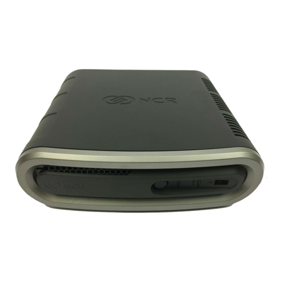
Product Overview Operator Controls Disk Activity LED Power Switch USB Port Power LED 28561 Cabinet Security The 7601 has easy access to the internal components. However, the case can be secured to a fixed object (desk, pole, etc) by attaching a standard Kensington lock to the Security Hasp. In addition a small padlock can be attached to the hasp to prevent the unit from being opened. Security Hasp 28569... -
Page 9: Serial Number/Model Number Label
Product Overview Serial Number/Model Number Label The serial number and model number are included on a label located on the bottom of the unit. A Certificate of Authenticity label is also included if the terminal is shipped with a pre‐installed Operating System. Model/Serial Number Label Certificate of Authenticity Label 28563... - Page 10 Product Overview...
-
Page 11: Chapter 2: Diagnostics
Diagnostics Chapter 2: LED Diagnostic Indicators The two front panel LEDs also function as diagnostic indicators, defined as follows. Note: The cell colors indicate the color of the LED at that particular time. Disk Activity LED Power Switch USB Port Power LED 28561 Current System Disk Activity Suspect Component System State Power LED Corrective Action Operation Normal Operation System ON Normal Operation System ON with Flashing HDD Activity (HDD... - Page 12 Diagnostics Current System Disk Activity Suspect Component System State Power LED Corrective Action Operation • OFF Power System • OFF 1. Check AC power to • AC Present • Not in Standby 2. Check P/S • External P/S 3. Check connection between unit and P/S 4. Check power connection from Back Panel to Motherboard and Motherboard to Front Panel 5.
- Page 13 Diagnostics Current System Disk Activity Suspect Component System State Power LED Corrective Action Operation POST • Display Stopped Prior to Flashing No Display: 1. Check for power to Boot (1/Sec) • Motherboard display if no display • Peripheral 2. Check cable connection between Motherboard and display 3. Check for properly functioning display 4.
-
Page 14: Loadable Diagnostics
Diagnostics Loadable Diagnostics The Loadable Diagnostics provide a means to test terminal hardware and the RS 232/ USB connected peripherals, independent of system software. The software is available on CD ROM: NCR Loadable Diagnostics LPIN: D370‐0746‐0100 The diagnostics consists of two Linux‐based bootable CD ROMs: • E‐Box Tests • Peripheral Tests ‐ A minimum of 512 MB of memory is required to run the Peripheral Tests. The following sections provide instructions about how to load the diagnostics and a few sample tests to familiarize you with how the software functions. Loading the Diagnostics You can load the software using the following devices. • Internal DVD/CDROM Drive (Peripheral Tests only) • TEAC External USB CD ROM Drive (2336‐K208) • NCR Services: External CDR/W DVD‐ROM Drive (603‐9014774) -
Page 15: Connecting An External Usb Cd-Rom Drive
Diagnostics Connecting an External USB CD-ROM Drive The Peripheral Tests can be run from an external CD ROM drive. 1. Connect the external USB CD‐ROM drive to a USB connector on the terminal. E 12V F 12V C 24V USB 2.0 DC Power DC Power AC Power 29840 2. Connect the Power Supply to the DC Power connector on the CD ROM and to an AC outlet. -
Page 16: Running The Terminal Diagnostics
8. If you are using the integrated CD/DVD Drive select CD/DVD:P1-DV-28S-V. If you are using the external USB CD Drive select USB:TEAC CD-W552E. Running the Terminal Diagnostics Insert the E‐Box Tests CD in the CD‐ROM drive and boot the system. When the system is boots the Main Menu is displayed. ################################################### NCR Loadable E-Box Diagnostics (CD Version) Linux Base: NSPOS9 Copyright © 2007, 2008 NCR Corporation ################################################### NCR Loadable Diagnostics 1) Perform Terminal Diagnostics 2) View Loadable Diagnostic Documentation on CD... -
Page 17: Storage/Ide Drives Test
Diagnostics Storage/IDE Drives Test Select Storage/IDE Drives (3) and press [Enter]. Select the device you want to test. Storage/IDE/SATA Device Information 1) Primary Master:[NOT DETECTED] 2) Primary Slave:[NOT DETECTED] 3) Primary Master:[NOT DETECTED] 4) Primary Slave:[NOT DETECTED] 5) SATA 1:[SATA Hard Disk] 6)SATA 2:[NOT DETECTED] 7)SATA 3:[NOT DETECTED] 8)SATA 4:[NOT DETECTED] 0) Exit Storage/IDE Device Information Select: 2. -
Page 18: Serial Ports Test
0)Exit RS-232 Serial Ports Select: From this menu you can change the serial port configuration for diagnostic purposes or test a serial port (Serial Turnaround Plug required). System Information (CPU, DMI, etc.) Test Select System Information (CPU, DMI, etc.) (5) and press [Enter]. The terminal information is displayed. For example: Terminal Information Terminal:7601-1000-8800 Serial Num:50-12345678 UUID: 00020003-0004-0006-000700080009 BIOS Version:NCR BIOS 6.2.2.0 CPU Version:Genuine Intel(R) CPU 575 @ 2.00GHz CPU Speed:1995.109 MHz 0) Exit Terminal Information Select:... -
Page 19: System Memory Test
Diagnostics System Memory Test Select System Memory (6) and press [Enter]. The system memory information is displayed. For example: Terminal System Memory System Memory is reported by the OS as: 984252 KB Estimate of physical memory present is: 1024 MB 0) Exit Terminal System Memory Select:... -
Page 20: Running The Peripheral Diagnostics
Diagnostics Running the Peripheral Diagnostics Navigation Navigation around the peripheral screens is done using the keyboard. The arrow keys are used to move to the menu items. The [Enter] key is used to select the item. Running the Tests Insert the Peripheral Tests CD in the CD‐ROM drive and boot the system. When the system is boots the Main Menu is displayed. This may take a minute or so to load into RAM. At the Main Menu, highlight Peripherals and press [Enter]. FitClient Manager LE + Peripherals + Platform The Peripheral Diagnostics Menu contains the options available for you to test. FitClient Manager LE - Peripherals Hard Totals Keylock Line Display MICR POS Printer Scale Scanner Tone Indicator + Platform MSR Test 1. -
Page 21: Printer Test
Diagnostics Printer Test Using the arrow keys, highlight POS Printer and then press [Enter]. 2. Press [->] to move to the right side window. Select the Logical Name field and then press [Enter]. 4. Select the correct printer profile. Note: If your Printer is not listed you can modify the parameters of the current one or create a new one by selecting Create a New Name. Press [F8] to save all changes. Keep in mind that all changes are lost when you end this session. 5. Make any necessary changes to the profile. Example: If your printer is connected to a different COM port than what is shown in the profile you can change the setting. Press [F8] to save the changes to the current profile. Highlight Run Interactive Diagnostic and then press [Enter]. 7. Exit the test by pressing [Esc]. Scanner Test 1. Using the arrow keys, highlight Scanner and then press [Enter]. 2. Press [->] to move to the right side window. 3. Select the correct Scanner profile. Note: If your Scanner is not listed you can modify the parameters of the current one or create a new one by selecting Create a New Name. Keep in mind that all changes are lost when you end this session. -
Page 22: Tone Indicator Test
Diagnostics Tone Indicator Test Using the arrow keys, highlight Tone Indicator and then press [Enter]. 2. Press [->] to move to the right side window. 3. Select the correct keyboard profile. Note: If your keyboard is not listed you can modify the parameters of the current one or create a new one by selecting Create a New Name. Press [F8] to save all changes. Keep in mind that all changes are lost when you end this session. Highlight Run Interactive Diagnostics and then press [Enter]. 5. A audible tone is heard if the test is successful. 6. Exit the test by pressing [Esc]. -
Page 23: Chapter 3: Hardware Disassembly
Caution: This product does not contain user serviceable parts. Servicing should only be performed by a qualified service technician. Fuse Replacement Caution: For continued protection against risk of fire, replace only with the same type and ratings of fuse. Attention: Pour prévenir et vous protéger contre un risque de feu, remplacer la fusible avec une autre fusible de même type, seulement. Lithium Battery Warning Caution: Danger of explosion if battery is incorrectly replaced. Replace only with the same or equivalent type as recommended by the manufacturer. Discard used batteries according to the manufacturerʹs instructions. Attention: Il y a danger dʹexplosion sʹil y a remplacement incorrect de la batterie. Remplacer uniquement avec une batterie du même type ou dʹun type recommandé par le constructeur. Mettre au rébut les batteries usagées conformément aux instructions du fabricant. Battery Disposal (Switzerland) Refer to Annex 4.10 of SR814.013 for battery disposal. IT Power System This product is suitable for connection to an IT power system with a phase‐to‐phase voltage not exceeding 240 V. Peripheral Usage This terminal should only be used with peripheral devices that are certified by the appropriate safety agency for the country of installation (UL, CSA, TUV, VDE) or those which are recommended by NCR Corporation. Caution: DO NOT connect or disconnect a printer, keyboard, or any other terminal‐ powered peripheral while the terminal is powered on. Doing so may result in peripheral or system damage. - Page 24 Hardware Disassembly Grounding Instructions In the event of a malfunction or breakdown, grounding provides a path of least resistance for electric current to reduce the risk of electric shock. This product is equipped with an electric cord having an equipment‐grounding conductor and a grounding plug. The plug must be plugged into a matching outlet that is properly installed and grounded in accordance with all local codes and ordinances. Do not modify the plug provided ‐ if it will not fit the outlet, have the proper outlet installed by a qualified electrician. Improper connection of the equipment‐grounding conductor can result in a risk of electric shock. The conductor with insulation having an outer surface that is green with or without yellow stripes is the equipment‐grounding conductor. If repair or replacement of the electric cord or plug is necessary, do not connect the equipment‐grounding conductor to a live terminal. Check with a qualified electrician or service personnel if the grounding instructions are not completely understood, or if you are in doubt as to whether the product is properly grounded. Use only 3‐wire extension cords that have 3‐prong grounding plugs and 3‐pole receptacles that accept the productʹs plug. Repair or replace damaged or worn cords immediately.
-
Page 25: Cable Connectors
Hardware Disassembly Cable Connectors The following illustrations identify the peripheral cable connectors. For convenience there is a USB connector located on the front of the unit. E 12V F 12V C 24V 28047... -
Page 26: Terminal Disassembly Procedures
Hardware Disassembly Terminal Disassembly Procedures This section explains how to disassemble the 7601 for service purposes. Warning: Disconnect the AC power before disassembling the Terminal. Removing the Rear Cable Cover Note: The Rear Cable Cover is optional. 1. 1.Loosen the Captive Screws (2) that secure the cover to the rear of the terminal. Display Cable (If located on top of terminal) Captive Screws Power/LAN Cables Rear Cable Cover 28679 2. Pivot the cover as shown below to disengage the hinges to remove it from the terminal. 28680... -
Page 27: Opening The Top Cover
Hardware Disassembly Opening the Top Cover 1. Slide the Cover Latch located on the bottom of the unit forward to unlock the Top Cover. Note: First remove the Security Lock on the rear of the unit if present. Cover Latch 28591 2. Pivot the Top Cover open and gently rest it on the table surface. Caution: When opening the cover, do not allow it to drop onto the table surface. The mechanical shock can damage the HDD. 28747... -
Page 28: Removing The Hard Disk Drive
Hardware Disassembly Removing the Hard Disk Drive The Hard Disk Drive (HDD) is mounted on the inside of the Top Cover. 1. Squeeze the latches on the HDD Bracket as shown to unlock the bracket from the Top Cover and slide the HDD Bracket as shown until you see Unlocked displayed in the opening in the HDD Bracket. HDD Bracket 28593 2. Tilt the HDD on one edge to remove it from the Top Cover Bracket and disconnect the HDD Data/Power Connector. HDD Data/Power Connector 28596... -
Page 29: Replacing The Motherboard
Hardware Disassembly Replacing the Motherboard Removing the Motherboard 1. Disconnect any external cables on the back of the terminal. 2. Open the Top Cover. 3. Remove the Daughter Card. a. Disconnect the Data Cable and Power Cable from the Daughter Card Assembly. Power Cable Data Cable Daughter Card Assemby 28748... - Page 30 Hardware Disassembly b. Remove the screws (2) from the back of the terminal that secure the Daughter Card Assembly. Screws 28682 4. Remove the Cooling Solution Assembly a. Remove the screws (2) that secures the Cooling Solution Assembly to the chassis. b. Loosen the spring‐loaded captive screws (6) that secure the Cooling Solution Assembly to the Motherboard. Note: Use a sequential rotating pattern when loosening the spring‐loaded screws. Loosen each screw a little at a time to evenly raise the Heatsink from the CPU. Screws Captive Screws (6) 28749...
- Page 31 Hardware Disassembly c. Remove the Cooling Solution Assembly from the Motherboard. 28751 5. Disconnect the Power Switch Ribbon Cable from the Motherboard. Power Switch Ribbon Cable 28750...
- Page 32 Hardware Disassembly 6. Disconnect the COMMC and COMD Cables from the Motherboard. COMD COMC 28752 7. Disconnect the remaining cables from the Motherboard. COMD DC Power In COMC Line Out PS/2 SATA Power HDD SATA Front Panel Board 28753...
- Page 33 Hardware Disassembly 8. Remove the screws (4) that secure the Motherboard to the chassis base. Power Switch Ribbon Cable 28754 9. Tilt the Motherboard as shown below and shift it toward the front of the cabinet to remove the connectors from the rear of the chassis. 28769...
- Page 34 Hardware Disassembly Use care in handling the Processor Board. Solder joints can be broken if the board is allowed to be flexed. Use two hands to handle the board. 28760 10. Remove the Memory Module(s) from the Motherboard. See the Replacing a Memory Module section. 11. Remove the CPU Module from the Motherboard.
- Page 35 Hardware Disassembly a. Using a small flat‐blade screwdriver, turn the ZIFF connector locking screw one half turn counter‐clockwise to release the CPU. CPU Socket Latch 28761 b. Note the orientation of the CPU Module (gold triangle location). c. Carefully remove the CPU and place it in an anti‐static packing, which protects the CPU pins from becoming damaged.
-
Page 36: Installing The New Motherboard
Hardware Disassembly Installing the New Motherboard 12. Install the CPU Module. a. Make sure the ZIFF Locking Screw is in the unlocked position (fully counter clockwise). b. Correctly position the new CPU over the CPU Socket, with the gold triangle located as shown below. Caution: Do not touch the CPU contacts. c. Do not insert the CPU at an angle or force the CPU into the socket. d. Drop it in by its own weight. Gold Triangle 28762 Incorrect Pin 1 Markers Pins Correct 26158... - Page 37 Hardware Disassembly e. Using a small flat‐blade screwdriver, turn the ZIFF connector locking screw one half turn clockwise to lock the CPU. Note: Make sure the CPU remains flat and fully seated while locking the socket. CPU Socket Latch 28761a Verify the boardʹs jumper settings match the old Motherboard. 13. Install the Memory Module(s). 14. Install the new Motherboard in the terminal chassis. 15. Connect all of the Motherboard cables. ...
-
Page 38: Installing The Cooling Solution Assembly
Hardware Disassembly Installing the Cooling Solution Assembly Before you install the Cooling Solution Assembly replace the Thermal Pads with Thermal Grease. 16. Remove the Thermal Pads from the Cooling Solution Assembly surfaces. 17. Apply thermal grease to the CPU and Northbridge Modules. Use approximately one quarter of the contents of the grease syringe to the top of the both as shown below. Do not use the entire contents of the syringe. Too much grease can block the airflow around the CPU heat spreader. The goal is for the processor chip to be evenly covered with grease once the heatsink is installed. Thermal Grease 26164 • Do not apply the grease with a bare finger tip or talc‐coated glove. Oils on skin and particulate on the glove can contaminate the grease. • Make sure none of the grease gets on the circuit board. Heatsink grease is a strong electrical conductor and can short signals on the board if it crosses trace paths. • Recheck to make sure no foreign contaminants are present on either the bottom of the heat sink or the top of the CPU. - Page 39 Hardware Disassembly 18. Install the Cooling Solution Assembly on the Motherboard. a. Position the assembly over the CPU and tighten the six spring‐loaded screws. Note: Use a sequential rotating pattern when loosening the spring‐loaded screws. Tighten each screw a little at a time to evenly raise the Heatsink from the CPU. 28751a b. Secure the assembly to the chassis (2 screws). Screws 28749a Note: After powering up the terminal, re‐flash the BIOS to ensure the latest version is installed and verify that the terminal is fully functional (see the BIOS Updating Procedures chapter in the NCR RealPOS 60 User Guide (B005 0000 2011).
-
Page 40: Removing The Front Panel Board
Hardware Disassembly Removing the Front Panel Board 1. Open the Top Cover. 2. Disconnect the Front Panel USB Cable and Power Switch Ribbon Cable from the Front Panel. Power Switch Ribbon Cable Front Panel USB Cable Front Panel Board 28755 3. Remove the screws (2) that secure the Front Panel Board to the Front Panel. -
Page 41: Replacing The Memory Module
Hardware Disassembly Replacing the Memory Module 1. Remove power from the terminal. 2. Open the Top Cover. 3. Open the latches at the ends of the memory socket to release the module. Memory Module Latches 28756 4. To install the module, align it with the socket and push it straight down, applying down pressure on the ends smoothly with both hands as indicated by the arrows below. (Note that the connector is keyed.) 28757... - Page 42 Hardware Disassembly 5. Ensure that the edges of the module engage the latches and that the latches are completely closed. 28758...
-
Page 43: Replacing The Lithium Battery
Hardware Disassembly Replacing the Lithium Battery Caution: Danger of explosion if battery is incorrectly replaced. Replace only with the same or equivalent type as recommended by the manufacturer. Discard used batteries according to the manufacturerʹs instructions. 1. Remove power from the terminal. 2. Open the Top Cover. 3. Note the batteryʹs polarity before removing it so that you can replace the battery correctly. 4. Press the Retaining Clip to the side as shown and then remove the battery from of the socket. Lithium Battery Retaining Clip 28759 5. Insert the new battery by pushing it straight down until it is tightly locked. Battery polarity is indicated on the Motherboard next to the battery connector. 6. Close the Top Cover. 7. Apply AC Power to the Terminal. 8. Run Setup and set defaults. Set the Date/Time and make any desired special settings. - Page 44 Hardware Disassembly...
-
Page 45: Chapter 4: Circuit Boards
Circuit Boards Chapter 4: Motherboard Connectors DVI-D COMB COMA 12 V USB+ Power 24 V USB+ Power Cash Drawer DC Power In DC Power Front Panel COMC SATA_1 (Power) SATA0 SATA1 COMD SATA_2 (Power) Not Used SATA_3 (Power) SATA2 PS/2 Line Out Mic In 28763... -
Page 46: Serial Port Jumpers
Circuit Boards Serial Port Jumpers There are four serial ports available. The default setting for all is 12V. COMA COMB COMC COMD 12 V * Default setting Ring Indicator 28764... -
Page 47: Fuses
Circuit Boards Fuses F5, 10 A, 125 V Littelfuse P/N: 0154010.DRT NCR P/N: 006-8616904 (Motherboard DC Power In) F1, 3 A, 125 V Littelfuse P/N: 0154003.DTR NCR P/N: 006-8610783 (Printer & Cash Drawer +24V) 29434... -
Page 48: A_On And Rsd/Fsd Jumpers
Circuit Boards A_ON and RSD/FSD Jumpers The 7601 Motherboard is used in both Retail and Financial environments. These two jumpers are used to configure the board properly for these environments. The A_ON jumper is used to cause the terminal to turn on automatically whenever AC power is applied. It should always be set to Pins 2 ‐ 3 for the 7601. The RSD/FSD jumper should always be set to the Retail setting (RSD) for the 7601. A_ON 7601 Position Used RSD/FSD 7601 Position Used 28767... -
Page 49: Connector Pinouts
Circuit Boards Connector Pinouts The LED on the right is yellow and indicates Link/Activity when lit/flashing. The LED on the left is Bi‐color and indicates the following when the yellow LED on the right side is lit: • Unlit ‐ 10M speed • Green: 100M speed Ethernet RJ‐45 & USB 1/2 Connector • 10/100 Base T Ethernet. • RJ Jack • Color: None specified. PIN No. Signal Description PIN No. Signal Description TD0+ TDO‐ TD1+ TD1‐ TD2+ TD2‐ TD3+ TD3‐ USB1, USB2 PIN No. Signal Description +5 V DATA0‐... - Page 50 Circuit Boards VGA Connector Protected by a self‐healing polyfuse: Protectronics EZ Fuse P/N SMD1812P160TF or NCR Approved Equivalent. Fuse can supply 1.1 A over the temperature range. • 15 pin D‐shell • VGA, SVGA or XGA • Color: Blue PIN No. Signal Description PIN No. Signal Description GREEN BLUE Ground Analog Ground Analog Ground Analog Ground Ground VID_SDA HSYNC VSYNC CON_DDCCL...
- Page 51 Circuit Boards Serial Port Connectors (A, B, C, D) The Motherboard includes four external RS‐232 ports with the following characteristics: • Standard 9 pin D‐shell • Ports have a shunt to select between +12 V and normal RI functionality. The default is 12 V. These ports are marked with the lightning bolt symbol to signify its powered capability. • Maximum power capability is 1.5 A from any one port with a maximum combined capability of 3.0 A for all ports. Total +12 V power peripheral current (RS‐232 and USB) must NOT exceed 3.0 A. • The +12 V outputs from the powered ports are protected by a self healing fuse. • If a port does not have +12 V connected to pin 9, that port can be used to wake up the terminal from Standby via activity on the RI pin. • COMA and COMMB ports are provided in a DB9 dual stack configuration. Color: Teal or Turquoise • COMC and COMD are individually mounted on the Back Panel and connected to the Motherboard with cables. Color: Black PIN No. Signal Description DCD (Data Carrier Detect) RXD (Receive Data) TXD (Transmit Data) DTR (Data Terminal Ready) GND (Ground) DSR (Data Set Ready) RTS (Request to Send)
- Page 52 Circuit Boards +24 V USB +Power Port (G) • The 24V Powered USB port is capable of supplying 24V at 0.5A continuous and 3.0A peak. The 24V is fused with a socketed fuse: Littelfuse P/N 154003TDR or NCR P/N 006‐8610783. • 24 V at 2.3A (max) Note: This port may also be used to provide power only for a printer that uses an RS 232 I/F to connect to the 7601. • Color: Warm Red (Pantone 032C) PIN No. Signal Description PIN No. Signal Description USB+5V 24V_RET USBDATA‐ +24V USBDATA+ +24V Ground +24V_RET...
- Page 53 Circuit Boards +12 V USB +Power port There are four external +12 V USB +Power ports, one standard on the Motherboard (C) and three on the optional Daughter Card (E, F, G). • The 12V Powered USB ports are capable of supplying 12V at 2.0A max. Each port is fused with a self healing poly‐fuse: Polytronics Everfuse P/N: SMD2920P300TF/15 or NCR approved equivalent. • A single self‐healing polyfuse protects the +5V of both ports (12V and 24V USB + Power ports): Polytronics Everfuse P/N: SMD1812P160TF or NCR approved equivalent. • Color: Teal (Pantone 3262C) • Connector: Foxconn P/N UB11123‐GHT2‐4F or NCR approved equivalent • 12 V at 1.5 A (max) • Color: Teal PIN No. Signal Description PIN No. Signal Description Ground USBDATA‐ +12V USBDATA+ +12V Ground Ground SATA PIN No.
- Page 54 Circuit Boards Cash Drawer Kickout The 7601 Motherboard provides support for two 24V Cash Drawers on a single connector. The two cash drawers share a common switch status signal. The 24V is the same fused +24V used for the +24V USB plus power port. • Color: None specified • 6‐position RJ45 connector PIN No. Signal Description Frame GND Solenoid A Drawer A/B Open/Close Status +24 V Solenoid B Logic GND...
-
Page 55: Chapter 5: Power Supply
Power Supply Chapter 5: The 7601 uses an external power brick to power the terminal and its powered peripherals. Caution: The 7601 requires the NCR 24 V power supply that is shipped with the terminal. Use of other power bricks may cause damage to the unit. • 24 V, 150 W Continuous Output power • MEPS Level V mark (efficiency 87% minimum), Energy Star 5.0 capable • Auto Detection to switch between 115VAC or 230VAC • PFC per EN61000‐3‐2 (120VAC / 240VAC operation ) • Fanless, sealed case • 300,000 hour Mean Time Between Failures (MTBF) • RoHS and WEEE Compliant • Supports 24V retail printers at 55W maximum when connected to 7601 1416-C325-0032 006-1009037 - U.S. Standard International power cables: 1416-C320-0030 006-8601011 - SEV 1416-C321-0030 006-8601012 - U.K. -
Page 56: Ac Input
Power Supply AC Input Input Current Max. Range Nominal Vrms Minimum Vrms Maximum Vrms Arms Low (115) 100‐127 2.2 A High (230) 200‐240 1.2 A Input Frequency Range 47 Hz – 63 Hz DC Output Output Voltage Minimum Maximum Regulation 24 V 0 A 6.25 A 10% / ‐5% Maximum Rated Output Power The maximum rated output power as defined as the continuous load is 150W. -
Page 57: Chapter 6: Clearing The Cmos/Password
Clearing the CMOS/Password Chapter 6: The CMOS/Password can be cleared as follows. 1. Turn the power off and disconnect power from the Terminal. 2. Open the Top Cover. 3. Temporarily move the shunt from the Normal position (Pins 1‐2) to Pins 2‐3. 4. Move the shunt back to the Normal position. 5. Close the Top Cover. 6. Connect power and turn on the terminal. CMOS/Password is cleared when power is applied. CMOS Clear Jumper (CLR_CMOS1) Normal Temporarily move Position Jumper to this position 28766... - Page 58 Clearing the CMOS/Password...
-
Page 59: Appendix A: Irq Assignments
IRQ Assignments Appendix A: Priority Default Function System Timer Keyboard Controller Programmable Interrupt Communication Port (COM1) Communication Port (COM2) Printer Port (LPT2) Floppy Disk Drive Controller Printer Port (LPT1) System CMOS/Real Time Clock ACPI Controller IRQ Holder for PCI Steering IRQ Holder for PCI Steering PS/2 Compatible Mouse Port Numeric Data Processor Primary IDE Channel Secondary IDE Channel * IRQ that is usually available for ISA or PCI devices.