
Related Manuals for NCR RealPOS 70XRT 7403


Summary of Contents for NCR RealPOS 70XRT 7403
- Page 1 NCR RealPOS 70 (7403) POS Workstation Release 1.2 Site Preparation Guide B005‐0000‐1873 Issue C...
- Page 2 The product described in this book is a licensed product of NCR Corporation. NCR is a registered trademark of NCR Corporation. NCR RealPOS is either a registered trademark or a trademark of NCR Corporation in the United States and/or other countries. UniWinDriver, TSHARC and Hampshire are trade names of Hampshire Company, Inc. Copyright 1995 ‐ 2008 Hampshire Company, Inc. It is the policy of NCR Corporation (NCR) to improve products as new technology, components, software, and firmware become available. NCR, therefore, reserves the right to change specifications without prior notice. All features, functions, and operations described herein may not be marketed by NCR in all parts of the world. In some instances, photographs are of equipment prototypes. Therefore, before using this document, consult with your NCR representative or NCR office for information that is applicable and current. To maintain the quality of our publications, we need your comments on the accuracy, clarity, organization, and value of this book. Address correspondence to: Manager, Information Solutions NCR Corporation Discovery Centre 3 Fulton Road DD2 4SW Internet Address: http://www.info.ncr.com/eFeedback.cfm Copyright © 2009 By NCR Corporation Duluth, GA U.S.A. All Rights Reserved...
- Page 3 Preface This is a contractual document. It contains important warnings and confers important legal rights and obligations. You are advised to read it carefully. It is the responsibility of the customer to ensure that all installation preparations are complete and in compliance with NCR specifications and requirements and all applicable national, state, or local codes, regulations, and laws. Safety Requirements The NCR 7403 Terminal must be connected to an AC outlet that is near the terminal and is easily accessible by the operator. Warning: This unit contains hazardous voltages and should only be serviced by qualified service personnel. The on/off switch is a logic switch only. The AC line voltage primaries are live at all times when the power cord is connected. Therefore, disconnect the AC power cord before opening the unit to install features or service this terminal. Peripheral Usage The 7403 should be used only with peripheral devices that are recommended by NCR Corporation and are certified by the appropriate safety agency for the country of installation (UL, CSA, TUV, VDE). Safety and Regulatory Information The NCR RealPOS 70 conforms to all applicable legal requirements. To view the compliance statements see the NCR RealPOS Terminals Safety and Regulatory Statements (B005‐0000‐1589). ...
-
Page 4: About This Book
About this Book This book provides site preparation information for NCR 7403 Terminal components. Peripheral component and AC wiring site preparation information is NOT provided in this book. The associated reference documents are listed in the Related Site Preparation Data section. This book contains the information necessary for the preparation of a site conforming to the NCR specifications. It is very important that the site complies with the requirements specified in the document because, once the equipment has been installed, deficiencies in site preparation or the problems caused by these deficiencies are much more difficult to detect and correct. Further, failure to comply with these requirements or to take proper steps to protect equipment against risks identified in this document may cause serious damage to the equipment and to the customer ʹ s business. In addition to the need to comply with the requirements specified, electrical wiring, and mechanical systems must also comply with all relevant codes, laws, and regulations. It is important that the site be prepared by a customer or his agent who is fully conversant with the special requirements of electronic equipment. The responsibility of ensuring that the site is prepared in compliance with this document remains with the customer. For information and guidance purposes only, a list is provided, in general terms, of those matters for which the customer is responsible. This list is not intended to be comprehensive, and in no way modifies, alters, or limits the responsibility of the customer for all aspects of adequate site preparation. NCR staff will be available to answer questions relating to the contents of this document except where: • a customer has been notified that a full or partial consultancy service is available and/or that NCR will be willing to undertake a preliminary or final site survey and • the customer shall have entered into a formal contract with NCR for provision of the same. No comment, suggestion, or advice offered or not offered about preparation of the site nor any inspection of the site whether before or after preparation is to be taken as approval of the location of the site and equipment or its preparation and NCR will not be liable in respect of any comment, suggestion, or advice given by its staff or in ... -
Page 5: Table Of Contents
Table of Contents Introduction Model Numbers Customer Responsibilities Third Party Peripheral Certification LAN Communications Dimensions 7403 Terminal (15”) w/Base..................5 7403 Terminal (17”) w/Base..................6 7403 Terminal (15”, Modular Configuration)............7 7403 Terminal (17”, Modular Configuration)............8 Integrated VFD Customer Display (7403‐K451) ........... 8 Integrated 12.1” 5942 Customer Display ............... 9 Integrated 15” 5942 Customer Display ..............10 Integrated 15” 5965 Customer Display ..............11 Integrated 15” 5966 Customer Display ..............12 Integrated 6.5” 5982 Customer Display ............... 13 Integrated 5975 Customer Display ............... 14 Wall Mount (7403‐K320)..................16 Wall Mount (7403‐K321).................. - Page 6 Tall Pole Mount ....................25 Base Plate Mounting Hole Dimensions ............26 Cash Drawers......................27 NCR 2181 Cash Drawer ................... 27 NCR 2186 Compact Cash Drawer ..............27 NCR 2189......................28 Component Weights Service Clearance Requirements Electrical Requirements 7403 Electrical Requirements ................. 30 Peripheral Power Requirements ................30 Store AC Wiring Requirements................30 Environmental Requirements Barometric Pressure ....................31 Temperature......................31 Humidity ........................31 Airflow Requirements External Cable Routing External Peripheral System Cables Printer Cables......................35 Powered USB .....................
- Page 7 Powered RS‐232 (5975)..................38 Power (5942 12”) ....................38 Ethernet, 10/100/1000BaseT..................39 Dual Cash Drawer, Y‐Cable................... 39 Power Cables......................39 Revision Record Issue Date Remarks A Nov 2008 First issue B July 2009 Release 1.1 C Dec 2009 Release 1.2 ...
- Page 9 NCR RealPOS 70 Site Preparation Introduction This document provides the information necessary to prepare a site to NCR specifications prior to installing an NCR RealPOS 70 (also referred to as NCR 7403). The site must be properly prepared before the terminal is installed, because site preparation deficiencies may be difficult to detect and correct after installation. The NCR 7403 consists of separate pieces that may be combined in a variety of configurations. The System Configuration Diagram section identifies the individual components. Certain combinations are mutually exclusive. You must determine the equipment that will actually be installed before proceeding with the site preparation. 26026 ...
-
Page 10: Model Numbers
NCR RealPOS 70XRT Site Preparation Model Numbers Major Model Description 7403‐1000 Intel Celeron processor, 1GB DDR2, No Hard Disk 7403‐1001 Intel Celeron processor, 512MB DDR2, Hard Disk 7403‐1200 Intel Dual Core T1600 processor, 1GB DDR2, No Hard Disk 7403‐1300 Intel Core2 Duo T7500 processor, 2GB DDR2, No Hard Disk 7403‐F011 LCD Touch Display, 15”, Capacitive (Used with 7403 Base only) 7403‐F015 LCD Touch Display, 15”, Capacitive (7403 Base or remote mount) 7403‐F017 LCD Touch Display, 17”, Capacitive (7403 Base or remote mount) 7403‐F025 LCD Touch Display, 15”, Resistive (7403 Base or remote mount) ... -
Page 11: Customer Responsibilities
NCR RealPOS 70XRT Site Preparation Customer Responsibilities Before the system can be installed, the customer must perform or provide the following: • When required by NCR, provide the NCR Customer Services representative with appropriate drawings that indicate: • Equipment location • Site wiring (power and communications, paths and lengths) • Location of other equipment that may generate electrical noise, electromagnetic interference, or heat • Make building alterations necessary to meet wiring and other site requirements • Provide and install all communications cables, wall jacks, special connectors, and associated hardware • Provide and install necessary power distribution boxes, conduits, grounds, lightning protection devices, and associated hardware • Ensure all applicable codes, regulations, and laws (including, but not limited to, electrical, building, safety, and health) are met • Provide and install auxiliary power or other equipment as required • Provide storage or service areas as required • Meet all system/unit environmental requirements • Provide and install floor coverings and environment systems that limit or control static electricity build‐up and discharge In general, keep the NCR equipment area free from dust, smoke, lint, and other ... -
Page 12: Lan Communications
NCR RealPOS 70XRT Site Preparation Third Party Peripheral Certification Third party peripherals must be certified with the POS terminal or a potential ESD issue can occur. Third party peripherals include any electrically powered devices connected to the POS terminal that is not an NCR branded product or a certified solution advocated by NCR. Examples of third party products include printers, external CD‐ROM drives, cash drawers, cigarette boxes, pin pad devices, etc. Peripherals tend to be less sensitive to electrostatic damage when directly grounded through their power cords. If the peripheral is powered by the terminal and has no dedicated ground, then all of the ESD energy is coupled into the port connection. Some devices may require the use of an in‐line galvanic isolator/surge protector in order to prevent problems. The NCR TPP/SCER process is designed to evaluate third party peripherals and determine whether additional protective devices are needed. The NCR Workstation and Peripherals AC Wiring Guide (BST0‐2115‐53) contains additional information on this subject. LAN Communications The NCR 7403 Terminal supports Ethernet 10/100/1000baseT Local Area Network (LAN) communication protocol. For Ethernet communications wiring specifications, refer to the NCR Ethernet Communication Wiring Guide (BST0‐2118‐82). ... -
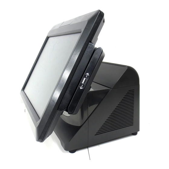
Page 13: Dimensions
NCR RealPOS 70XRT Site Preparation Dimensions 7403 Terminal (15”) w/Base 394 mm (15.5 in.) 368 mm (14.5 in.) 394 mm (15.5 in.) 193 mm (7.6 in.) 375 mm 240 mm (14.75 in.) (9.4 in.) 318 mm (12.25 in.) 381 mm (15.0 in.) -
Page 14: 7403 Terminal (17") W/Base
NCR RealPOS 70XRT Site Preparation 7403 Terminal (17”) w/Base 427 mm (16.8 in.) 400 mm (15.8 in.) 404 mm (15.9 in.) 193 mm (7.6 in.) 240 mm 396 mm (9.4 in.) (15.6 in.) 318 mm (12.25 in.) 427 mm (16.5 in.) 27697 ... -
Page 15: 7403 Terminal (15", Modular Configuration)
NCR RealPOS 70XRT Site Preparation 7403 Terminal (15”, Modular Configuration) 70 mm 394 mm (2.8 in.) (15.5 in.) 368 mm (14.5 in.) 328 mm (12.9 in.) 203 mm (8.0 in.) 240 mm 282 mm (9.4 in.) (11.1 in.) 26410 ... -
Page 16: 7403 Terminal (17", Modular Configuration)
NCR RealPOS 70XRT Site Preparation 7403 Terminal (17”, Modular Configuration) 77 mm 427 mm (3.3 in.) (16.8 in.) 400 mm (15.8 in.) 376 mm (14.8 in.) 203 mm (8.0 in.) 240 mm 282 mm (9.4 in.) (11.1 in.) 27698 ... -
Page 17: Integrated 12.1" 5942 Customer Display
NCR RealPOS 70XRT Site Preparation Integrated 12.1” 5942 Customer Display 305 mm 127 mm (12.0 in.) (5.0 in.) 337 mm (13.25 in.) 114 mm (4.5 in.) 26262 ... -
Page 18: Integrated 15" 5942 Customer Display
NCR RealPOS 70XRT Site Preparation Integrated 15” 5942 Customer Display 140 mm 350 mm (5.5 in.) (13.9 in.) 375 mm (14.75 in.) 107 mm (4.2 in.) 26263 ... -
Page 19: Integrated 15" 5965 Customer Display
NCR RealPOS 70XRT Site Preparation Integrated 15” 5965 Customer Display 140 mm 368 mm (5.5 in.) (14.5 in.) 394 mm (15.5 in.) 107 mm 26267 (4.2 in.) ... -
Page 20: Integrated 15" 5966 Customer Display
NCR RealPOS 70XRT Site Preparation Integrated 15” 5966 Customer Display 152 mm (6.0 in.) 394 mm (15.5 in.) 394 mm (15.5 in.) 107 mm (4.2 in.) 26268 ... -
Page 21: Integrated 6.5" 5982 Customer Display
NCR RealPOS 70XRT Site Preparation Integrated 6.5” 5982 Customer Display 89 mm (3.5 in.) 175 mm (6.9 in.) 315 mm (12.4 in.) 165 mm (6.5 in.) 27715 ... -
Page 22: Integrated 5975 Customer Display
NCR RealPOS 70XRT Site Preparation Integrated 5975 Customer Display 180 mm (7.1 in.) 5975-1xxx 5975-2xxx 224 mm (8.9 in.) 394 mm (15.5 in.) 26335 ... - Page 23 NCR RealPOS 70XRT Site Preparation There are four different length posts available for the display, in four inch increments. • 5975‐K834: 102 mm (4 in.) and 203 mm (8 in.) poles • 5975‐K836: 305 mm (12 in.) and 406 mm (16 in.) poles Note: The Rear Consumer Display Mount (7403‐K452) is also required. 800 mm (27.5 in.) 600 mm (23.5 in.) 500 mm (19.5 in.) 400 mm (15.5 in.) 26336 ...
-
Page 24: Wall Mount (7403-K320)
NCR RealPOS 70XRT Site Preparation Wall Mount (7403-K320) 244 mm 287 mm (9.6 in.) (11.3 in.) 26301 ... - Page 25 NCR RealPOS 70XRT Site Preparation 7.1 mm (0.28 in.) Use 6.4 mm (0.25 in) bolts. 102 mm 213 mm (4.0 in.) (8.4 in.) 178 mm (7.0 in.) 244 mm (9.6 in.) 26300 ...
-
Page 26: Wall Mount (7403-K321)
NCR RealPOS 70XRT Site Preparation Wall Mount (7403-K321) 73 mm (2.9 in.) 7.1 mm (0.28 in.) 178 mm Use 6.4 mm (7.0 in.) (0.25 in) bolts. 102 mm 258 mm (4.0 in.) (10.2 in.) 204 mm (8.0 in.) 45 mm (1.8 in.) -
Page 27: Printers
NCR RealPOS 70XRT Site Preparation Printers 7167 Thermal Receipt and Impact Slip Printer 174 mm (7.0 in.) 275 mm 10.8 in. 262 mm 190 mm (10.3 in.) (7.5 in.) 316 mm (12.5 in.) 19711g 7168 Thermal Receipt and Impact Slip Printer 181 mm (7.1 in.) -
Page 28: 7198 Thermal Receipt Printer
NCR RealPOS 70XRT Site Preparation 7198 Thermal Receipt Printer 139 mm 256 mm (5.5 in.) (10.1 in.) 145 mm 220 mm (8.7 in.) (5.7 in.) 23834c... -
Page 29: Remote Displays
NCR RealPOS 70XRT Site Preparation Remote Displays 5964 15-Inch Touch LCD 350 mm (13.75 in.) 353 mm 280 mm (13.9 in.) (11.0 in.) 21525 5942 12.1-Inch LCD Monitor 306 mm (12.0 in.) 304 mm (11.9 in.) 47 mm (1.9 in.) -
Page 30: 5942 15-Inch Lcd Monitor
NCR RealPOS 70XRT Site Preparation 5942 15-Inch LCD Monitor 353 mm (13.9 in.) 356 mm (14.0 in.) 228 mm (9.0 in.) 21524 5965 15-Inch LCD Monitor 394 mm (15.5 in.) 350 mm (13.75 in.) 273 mm 25820 (10.75 in.) -
Page 31: 5966 15-Inch Lcd Monitor
NCR RealPOS 70XRT Site Preparation 5966 15-Inch LCD Monitor 400 mm (15.7 in.) 220 mm 358 mm (8.7 in.) (14.1 in.) 26472 ... -
Page 32: 5975 Remote Customer Displays
NCR RealPOS 70XRT Site Preparation 5975 Remote Customer Displays There are two versions of the 5975. they have the same appearance and dimensions. • 5975‐1xxx 2x20 Remote Customer Display • 5975‐2xxx Graphical Remote Customer Display 224 mm (8.9 in.) 93 mm (3.7 in.) 229 mm (9.0 in.) 151 mm 123 mm (5.9 in.) (4.8 in.) 22916... -
Page 33: Tall Pole Mount
NCR RealPOS 70XRT Site Preparation Tall Pole Mount There are four different length posts available for the 5975 display, in four inch increments. 520 mm (20.5 in.) 420 mm (16.5 in.) 320 mm (12.5 in.) 215 mm (8.5 in.) 22917 Note: Heights greater than 215 mm (8.5 in.) should be screwed to the counter top. ... -
Page 34: Base Plate Mounting Hole Dimensions
NCR RealPOS 70XRT Site Preparation Base Plate Mounting Hole Dimensions 76 mm (3.0 in.) 76 mm (3.0 in.) 22912 ... -
Page 35: Cash Drawers
NCR RealPOS 70XRT Site Preparation Cash Drawers NCR 2181 Cash Drawer 442 mm (17.4 in.) 117 mm (4.6 in.) w/feet: 127 mm (5.0 in.) 467 mm (18.7 in.) 762 mm (30.0 in.) 24799 NCR 2186 Compact Cash Drawer 411 mm (16.2 in.) -
Page 36: Ncr 2189
NCR RealPOS 70XRT Site Preparation NCR 2189 464 mm (18.25 in.) 133 mm (5.25 in.) 527 mm (20.5 in.") Operating and Service Clearance for Drawer 330 mm (13.0 in.) 20434a ... -
Page 37: Component Weights
NCR RealPOS 70XRT Site Preparation Component Weights Terminal Component Weight kg (lbs.) 7403 Terminal 11.2 (24.6) 7403 Base 7.4 (16.3) 7403 Display 3.8 (8.3) 2181 Cash drawer 6.0 (13.3) 2186 Cash drawer 12.3 (27.0) 2189 Cash drawer 9.5 (20.9) 5942 12.1” Touch Monitor 2.8 (6.2) 5942 15” Touch Monitor 3.0 (6.6) 5965 Touch LCD 4.0 ... -
Page 38: Electrical Requirements
NCR RealPOS 70XRT Site Preparation Electrical Requirements 7403 Electrical Requirements The terminalʹs power cord plugs into the bottom of the terminal into a three‐wire, single‐phase, 120 or 240 VAC receptacle. The available power cords are described in the System Cables section. The terminalʹs internal power supply has a maximum output of 300 Watts and provides power to the terminal, one printer, and peripherals. 120 volt 240 volt Voltage Ranges 100 ‐ 127 VAC 200 ‐ 240 VAC Frequency 50/60 Hz 50/60 Hz Current (A) (Max.) 6.3 3.0 Current (A) (Typical) 3.0 1.5 Peripheral Power Requirements The number of peripherals that the terminal can support is dependent upon which peripherals are connected. For planning purposes, use the RealPOS 70 Power Matrix (B005‐0000‐1876) to calculate the power requirements for your specific system configuration. Note: This file requires Microsoft Excel to run. ... -
Page 39: Environmental Requirements Barometric Pressure
NCR RealPOS 70XRT Site Preparation Environmental Requirements Barometric Pressure The terminal operates within the following barometric pressure conditions: • Maximum operating altitude: 3,000 m (9,843 ft.) • Operating range of pressure: 105 to 69 kPa (15.2 to 10.0 lb./in.) Temperature The terminal operates over the temperature ranges shown below. Continuous operation must be avoided at or near the indicated temperature extremes or in locations where the temperature changes beyond the restrictions. Temperature Parameter Restriction Operating 5°C to 40°C (40°F to 104°F), dry bulb Storage ‐10°C to 50°C (14°F to 122°F), three months Shipping ‐40°C to 60°C (‐40°F to 140°F), one week Dew Point 26°C (79°F) maximum Humidity The terminal operates within the humidity ranges shown below. Continuous operation must be avoided at or near the indicated humidity extremes or in locations where the humidity changes beyond the restrictions. Never expose the terminal to condensation. Humidity Type Restriction Relative 10% to 90% Maximum change rate 10%/60 minutes ... -
Page 40: Airflow Requirements
NCR RealPOS 70XRT Site Preparation Airflow Requirements The ambient temperature must not exceed 40°C (104°F). Do not block the air vents on the terminal. These vents are necessary for cooling. 26294 Do not place the terminal in an enclosed area where sufficient ventilation is not available. Leave at least 100 mm (4 inches) of clearance on sides where air vents are located. ... - Page 41 NCR RealPOS 70XRT Site Preparation Minimum Clearances 100 mm (4 in.) 26954 ...
-
Page 42: External Cable Routing
NCR RealPOS 70XRT Site Preparation External Cable Routing The cables from the I/O Board are routed under the base and out the bottom of the unit. Cables from the Backplane Board are routed out an opening in the Cover and down the back of the terminal. Backplane Cable Routing I/O Board Cable Routing 26222 ... -
Page 43: External Peripheral System Cables
NCR RealPOS 70XRT Site Preparation External Peripheral System Cables Printer Cables Powered USB 497-0441177 - 1 m (1416-C088-0010) 497-0441178 - 4 m (1416-C088-0040) USB (Printer) 24V USB+ Power (Printer) (Terminal) 19.0 mm 23.0 mm Access Hole Diameters (0.75 in.) (0.9 in.) 19307 ... -
Page 44: Display Cables
NCR RealPOS 70XRT Site Preparation Display Cables 5975 Remote Customer Display (Powered RS-232) 497-0439734 - 1.0 m (1432-C043-0010) D-Shell Modular 9-Pin 10-Pin 497-0439735 - 4.0 m Receptacle Plug (1432-C045-0040) RS-232 Display (Terminal) 38.0 mm 19.0 mm Access Hole Diameters (1.5 in.) (0.75 in.) -
Page 45: Vga (5942, 5964, 5965, 5975)
NCR RealPOS 70XRT Site Preparation VGA (5942, 5964, 5965, 5975) 497-0435044 - 1m (1416-C972-0009) Sub Miniature D-Shell Sub Miniature D-Shell 15-Pin Plug 15-Pin Plug 497-0435045 - 4m (1416-C972-0040) (Display) (Host Terminal) 38.0 mm 38.0 mm Access Hole Diameters (1.5 in.) (1.5 in.) -
Page 46: Usb +Power (5942, 5964, 5965, 5975)
NCR RealPOS 70XRT Site Preparation USB +Power (5942, 5964, 5965, 5975) 497-0445076 - 1 m (1432-C156-0010) 497-0445077 - 4 m (1432-C156-0040) Powered USB Powered USB (Display) (Host Terminal) 19.0 mm 23.0 mm Access Hole Diameters (0.75 in.) (0.9 in.) 23434a ... - Page 47 NCR RealPOS 70XRT Site Preparation Ethernet, 10/100/1000BaseT 497-0433667 - 3.0 m Modular Modular 1432-C046-0030 8-Pin 8-Pin Plug Plug 19.0 mm 19.0 mm Access Hole Diameters (0.75 in.) (0.75 in.) 22584 Dual Cash Drawer, Y-Cable 497-0409394 - 0.6 m Cash (1416-C372-0006) DWR.
- Page 48 NCR RealPOS 70XRT Site Preparation...
-
Page 49: Ac Power Line Transient Protection
Transient Protection Appendix A: AC Power Line Transient Protection In the process of power distribution, transient electrical energy (including, but not limited to, lightning strikes, intermittent short circuits, and switching transients) can be introduced onto power lines. Such transient energy can be very damaging to electronic hardware, and can also cause data corruption. Under these circumstances, NCR recommends the use of AC power transient suppressors. Such protection devices are intended to guard against power line transients that can result in hardware damage and various system or program errors. Improvement of any deficiencies in power quality is a customer responsibility. Malfunction and/or component failure as a result of power quality problems are/is not covered by the NCR Maintenance Agreement. NCR accepts no liability for any such occurrence nor for its consequences. When power transient suppression is required, the suppressors used should meet the following minimum requirements: • Dissipate energy to match the appropriate application categories as defined by IEEE Standard 587. • Be of the voltage limiting (clipping), or tracking filter type. The suppressor must not clamp the voltage to zero, and must self‐recover after the passage of the transient. The suppressor may be of the hybrid type construction that makes use of various technologies in order to meet speed and dissipation requirements. • Upon failure, exhibit a positive indication of its failure such as a blown fuse or tripped breaker. • Be listed by the accepted safety organization for the country involved (UL, CSA, VDE, ETL, and so on) and the installation must conform to local, state, and national electrical codes and regulations. ... -
Page 50: Data Line Transient Protection
Appendix A: Transient Protection Data Line Transient Protection The nature of the transient phenomenon may extend to the data communication lines connected to this equipment. It is the responsibility of the customer to install and connect a data line transient suppression system to correct or prevent any deficiencies. Such systems must meet the following minimum requirements: • Be of the voltage limiting type and must self‐recover after passage of the transient. • Must be designed to avoid signal degradation for the given interface they are attached to. • Be installed in accordance with all applicable local, state, and national electrical codes and regulation. Note: NCR provides a full line of both AC power and data line transient surge suppressors to protect your RealPOS system and reduce downtime and extend the life of the RealPOS Retail Solution. For sizing and product information, please call NCR Site Preparation Services at 800‐257‐0458. The following product offerings are available from NCR Site Preparation Services: • UPS ‐Uninterruptible Power Systems – Provides battery backup for power outages and brownouts. – Includes AC and data line surge protection. – If needed, certain models provide basic voltage regulation. – Small size provides easy installation. • Line Conditioners / Filters – Incorporates an Isolation transformer or filter that provides 100% isolation ...