NCR 7601 User Manual
Hide thumbs
Also See for 7601:
- Hardware service manual (60 pages) ,
- Site preparation manual (50 pages)
Table of Contents
Advertisement
Quick Links
Advertisement
Table of Contents

Related Manuals for NCR 7601


Summary of Contents for NCR 7601
- Page 1 USER GUIDE NCR RealPOS 60 (7601) Release 2.0 B005-0000-2011 Issue E...
- Page 2 NCR, therefore, reserves the right to change specifications without prior notice. All features, functions, and operations described herein may not be marketed by NCR in all parts of the world. In some instances, photographs are of equipment prototypes. Therefore, before using this document, consult with your NCR representative or NCR office for information that is applicable and current.
- Page 3 Audience This book is written for hardware installer/service personnel, system integrators, and field engineers. Notice: This document is NCR proprietary information and is not to be disclosed or reproduced without consent. Safety Requirements The NCR RealPOS 60 conforms to all applicable legal requirements. To view the compliance statements see the NCR RealPOS Terminals Safety and Regulatory Statements (B005-0000-1589).
- Page 4 Use only 3-wire extension cords that have 3-prong grounding plugs and 3-pole receptacles that accept the product’s plug. Repair or replace damaged or worn cords immediately. References • NCR RealPOS 60 Site Preparation Guide (B005-0000-2011) • NCR RealPOS 60 Hardware Service Manual (B005-0000-2013) • NCR RealPOS 60 Parts Identification Manual (B005-0000-2014)
-
Page 5: Table Of Contents
ACPI Processor C-States Operator Displays NCR 5943 12.1-Inch LCD NCR 5943 15-Inch LCD NCR 5967 12-Inch Touch LCD NCR 5967 15-Inch Touch LCD NCR 5954 15-Inch DynaKey NCR 5982 6.5-Inch LCD Display NCR 5976 2x20 LCD Customer Display Keyboards NCR 5932 Keyboards... - Page 6 Keyboard Power NCR 5932-222x 64-Key PS/2 POS Keyboard NCR 5932-5xxx USB Alphanumeric Big Ticket Keyboard Features NCR 5932-65xx PS/2 Programmable POS Keyboard NCR 5932-66xx USB Programmable POS Keyboard Printers NCR 7167 Printer NCR 7168 Printer NCR RealPOS 7197 Printer NCR 7198 Printer...
- Page 7 Replacing the Hard Disk Drive Chapter 3: BIOS Setup Entering Setup How to Select Menu Options Restoring Factory Settings BIOS Default Values Main Menu Advanced Menu Chipset Menu Boot Menu Chapter 4: BIOS Updating Procedure Introduction Prerequisites Creating the Bootable Media Creating a Bootable CD Creating a Bootable USB Memory Drive BIOS Updating Procedures...
- Page 8 viii Revision Record Issue Date Remarks Oct 2010 First Issue Aug 2012 Release 1.1 Jul 2012 Updated Solid State Optimization chapter Jun 2013 Release 2.0...
-
Page 9: Chapter 1: Product Overview
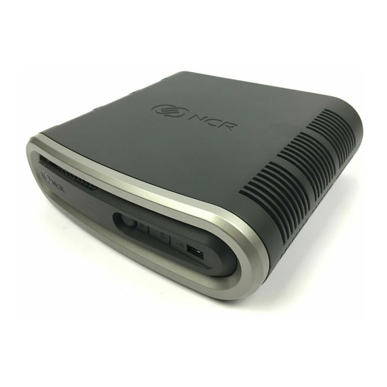
Chapter 1: Introduction The NCR RealPOS 60 (also known as NCR 7601) is a compact POS solution that combines the reliability and security of a retail-hardened POS terminal with the performance and flexibility of industry-standard PC technology. With an open architecture and Intel®... - Page 10 Product Overview Modular Configuration Stacked Configuration...
- Page 11 Product Overview An optional stand is available to mount the terminal vertically. Vertical Stand Configuration Flush Wall Mount (7409-K502)
-
Page 12: Operator Controls
LED Diagnostic Indicators. Cabinet Security The 7601 has easy access to the internal components. However, the case can be secured to a fixed object (desk, pole, etc) by attaching a standard Kensington lock to the Security Hasp. In addition a small padlock can be attached to the hasp to prevent the unit from... -
Page 13: Serial Number/Model Number Label
Product Overview Serial Number/Model Number Label The serial number and model number are included on the Certification Label located on bottom of the terminal. A Microsoft Certificate of Authenticity (COA) label is included if the terminal is ordered and shipped with a pre-installed Microsoft Operating System. There are two types of Microsoft COA stickers. -
Page 14: Features
• Intel Celeron G1610T (7601-3xxx) • Intel Core-i3 CPU (7601-4xxx) • Up to 4GB DDR3 Memory, 1333 MHz, 2 Memory Sockets (7601-3xxx) • Up to 8GB DDR3 Memory, 1333 MHz, 2 Memory Sockets (7601-4xxx) • Serial ATA (SATA) Hard Drive Interface •... -
Page 15: Operating Systems
Output ports Dual independent displays in Concurrent (Clone) and Extended Desktop modes are supported by the 7601. Analog display signals for legacy monitors. Standard DB-15 connector on rear IO. Standard DVI-D connector on rear IO, Foxconn QH11121-DBGH-4F or equivalent. -
Page 16: Power Management
The BIOS supports the Advanced Configuration and Power Management Interface (ACPI) 3.0 specification. A key feature of ACPI is that the operating system, not the BIOS, configures and implements power management. The 7601 terminal supports the Global system power states defined by ACPI: G3 Mechanical Off A computer state that is entered and left by a mechanical means. -
Page 17: Acpi Sleep States (S0 - S5)
Product Overview ACPI Sleep States (S0 - S5) Under the G1 sleeping state ACPI defines levels of system sleep state support. The 7601 supports the following sleeping states: • S0: Normal Powered-On state • S1 (Standby): The S1 sleeping state is a low wake latency sleeping state. In this state, no system context is lost (CPU or chip set) and hardware maintains all system contexts. - Page 18 1-10 Product Overview Power State **S3 Suspend S0Working S1Standby S4Hibernate **S5Soft Off to RAM Supported Description Fully • Video Back • Video Back • Video Back Functional Light Off Light Off Light Off • HDD Off • HDD Off • HDD Off •...
-
Page 19: Enabling Wake On Lan
Product Overview 1-11 Enabling Wake on LAN In order for Wake on LAN to function the Network driver must be enabled (factory default). The procedure for enabling the driver depends on which operating system you are using. Windows 7 Computer >>... - Page 20 1-12 Product Overview 2. Select Network adapters. 3. Right-click Intel(R) Ethernet Connection J217-LM >> Properties. 4. Under the Power Management tab, Wake on Magic Packet and Wake on Pattern Match and Wake on Magic Packet from power off state option boxes should be checked. Select after making any changes.
-
Page 21: Acpi Processor C-States
"throttling" process and through transitions into multiple performance states (P-states). Note: The 7601 Atom D2550 Processor supports C0 and C1 states. Support of deeper sleep states is not required due to its inherently low power consumption. -
Page 22: Operator Displays
Operator Displays NCR 5943 12.1-Inch LCD The NCR 5943 LCD is an LED backlit LCD display (XGA, 1024 x 768). The display is powered by the terminal from a +12V USB Plus Power port. The remote mount must be ordered separately. -
Page 23: Ncr 5943 15-Inch Lcd
1-15 NCR 5943 15-Inch LCD The NCR 5943 LCD is an LED backlit LCD display (XGA, 1024 x 768). The display is powered by the terminal from a +12V USB Plus Power port. The remote mount must be ordered separately. -
Page 24: Ncr 5967 12-Inch Touch Lcd
Product Overview NCR 5967 12-Inch Touch LCD The NCR 5967 Touch LCD is an LED backlit LCD display (XGA, 1024 x 768) with capacitive touch screen. The display is powered by the terminal from a +12V USB Plus Power port. The remote mount must be ordered separately. -
Page 25: Ncr 5967 15-Inch Touch Lcd
1-17 NCR 5967 15-Inch Touch LCD The NCR 5967 Touch LCD is an LED backlit LCD display (XGA, 1024 x 768) with capacitive touch screen. The display is powered by the terminal from a +12V USB Plus Power port. The remote mount must be ordered separately. -
Page 26: Ncr 5954 15-Inch Dynakey
Product Overview NCR 5954 15-Inch DynaKey The NCR RealPOS 5954 USB DynaKey is a Point-of-Sale (POS) keypad with a built-in 15- inch flat panel Liquid Crystal Display (LCD). Unique to the DynaKey is a set of ATM- style keys (DynaKeys), which are located beside the display. The functions of these keys change depending on the software application appearing on the LCD. -
Page 27: Ncr 5982 6.5-Inch Lcd Display
Product Overview 1-19 NCR 5982 6.5-Inch LCD Display The 5982 LCD Display is a terminal-powered color 6.5 Inch VGA LCD. Features • 5-inch VGA Monochrome LCD (640 x 480 VGA) • Contrast Control • LED Back Light • Keyboard Mount •... -
Page 28: Ncr 5976 2X20 Lcd Customer Display
Product Overview NCR 5976 2x20 LCD Customer Display The NCR RealPOS 5976-1xxx Customer Display is a 2-line x 20-character LED backlit Liquid Crystal Display (LCD), which can display any downloadable codepage of single byte characters. It supports both RS-232 and USB interfaces. -
Page 29: Mounting Options
• Table Mount, 4-in. Post • Table Mount, 8-in. Post • Table Mount, 12-in. Post • Table Mount, 16-in. Post • Integrated Mount for NCR 7456, 7457, 7458 Character Sets • Support for 19 character sets • 3 Character sets in base unit •... -
Page 30: Keyboards
Keyboards NCR 5932 Keyboards The NCR 5932 Keyboards are intended for harsh retail environments and contain an internal membrane to protect against objects such as paper clips, staple wires, pins, and so forth, from falling between the keys and damaging the electronics. This technology improves overall reliability not typically found in standard PC keyboards or many retail keyboards. -
Page 31: Ncr 5932-222X 64-Key Ps/2 Pos Keyboard
Product Overview 1-23 NCR 5932-222x 64-Key PS/2 POS Keyboard The NCR 64-Key POS Keyboard, designed for checkout environments where alpha entry is not required, includes 55 assignable function keys and a numeric keypad with 11 keys. Keylock Status Indicator 19746 Features •... - Page 32 1-24 Product Overview Keylock The Big Ticket and 64-key keyboards have a four-position keylock switch. The table following explains the keylock positions. Abbreviation Position Description Exception Used by the customer or service representative to perform low-level programming such as terminal diagnostics, configuring the terminal, or loading the terminal.
- Page 33 Product Overview 1-25 MSR (Magnetic Stripe Reader) The MSR is an optional feature that provides support for reading magnetically coded data cards. The keyboards support two different types of MSR: • ISO Tracks 1, 2, and 3 • JIS-II and ISO Track 2 (Big Ticket and full-featured 64-key keyboards only) Note: MSR signals are routed to the Wedge controller and passed into the system keyboard data stream.
-
Page 34: Ncr 5932-5Xxx Usb Alphanumeric Big Ticket Keyboard
Product Overview NCR 5932-5xxx USB Alphanumeric Big Ticket Keyboard Keylock 19586 The NCR USB Alphanumeric Big Ticket Keyboard is a multifunction keyboard that is two keyboards built into one. The keyboard consists of two major sections: • 38-key POS keyboard •... -
Page 35: Ncr 5932-65Xx Ps/2 Programmable Pos Keyboard
Product Overview 1-27 NCR 5932-65xx PS/2 Programmable POS Keyboard The NCR 5932 PS/2 Programmable POS Keyboard is a multifunctional keyboard that is two keyboards built into one. The keyboard consists of two major sections: • 32-key Point-Of-Sale Keyboard • PC type Alphanumeric Keyboard... -
Page 36: Ncr 5932-66Xx Usb Programmable Pos Keyboard
1-28 Product Overview NCR 5932-66xx USB Programmable POS Keyboard The NCR 5932 PS/2 Programmable POS Keyboard is a multifunctional keyboard that is two keyboards built into one. The keyboard consists of two major sections: • 32-key Point-Of-Sale Keyboard • PC type Alphanumeric Keyboard The keyboard includes the following features: •... -
Page 37: Printers
Printers NCR 7167 Printer The NCR 7167 Printer is a fast, quiet, relatively small and very reliable multi function printer. It prints receipts, validates and prints checks, and prints on a variety of single or multiple part forms. There is not journal as it is kept electronically by the host terminal. -
Page 38: Ncr 7168 Printer
Product Overview NCR 7168 Printer The NCR 7168 Printer is a fast, quiet, relatively small and very reliable multiple-function printer with front and back printing on the receipt paper capability. It prints receipts, validates and prints checks, and prints on a variety of single- or multiple-part forms. -
Page 39: Ncr Realpos 7197 Printer
1-31 NCR RealPOS 7197 Printer The NCR 7197 Printer is a fast, quiet, relatively small and very reliable printer. The printer can connect through a USB port or a serial port. It receives power from the 24V connector on the terminal or from an external power supply. -
Page 40: Ncr 7198 Printer
Product Overview NCR 7198 Printer The NCR 7198 printer is a fast, quiet, relatively small and very reliable printer with front and back printing on the receipt paper capability. The printer can connect through a USB port or a serial port. It can receive power from a power supply or through a USB+ power cable. -
Page 41: Chapter 2: Hardware Installation
Chapter 2: This chapter explains how to install the RealPOS 60 hardware, including out-of-box installation and how to install the optional peripheral devices. The 7601 is very flexible to install. This document discusses a typical configuration. Your configuration may require adjustments to the procedures. -
Page 42: Led Diagnostic Indicators
2-34 Hardware Installation LED Diagnostic Indicators The two front panel LEDs also function as diagnostic indicators, defined as follows. Note: The cell colors indicate the color of the LED at that particular time. Current Disk Suspect System System Power LED Activity Corrective Action Component... - Page 43 Hardware Installation 2-35 Current Disk Suspect System System Power LED Activity Corrective Action Component State Operation • OFF Power System • OFF 1. Check AC power to • AC Present • Not in Standby 2. Check P/S • External 3. Check connection P/S ON between unit and 4.
- Page 44 2-36 Hardware Installation Current Disk Suspect System System Power LED Activity Corrective Action Component State Operation POST Memory Memory Flashing 1. Check for properly Issue (1/Sec) installed memory 2. Replace memory 3. Replace Motherboard POST Motherboard No Display Flashing Replace Motherboard 1/4 Sec) POST Display...
- Page 45 Hardware Installation 2-37 Current Disk Suspect System System Power LED Activity Corrective Action Component State Operation Boot Time Boot Media (HDD, HDD is Boot Device: LAN) 1. Check HDD status in BIOS Setup 2. Check connections between HDD and Motherboard 3.
-
Page 46: Installing The Terminal
2-38 Hardware Installation Installing the Terminal 1. Connecting the External Cables 2. Connect the external cables to the connectors located on the rear of the unit. There is also a USB connector on the Front Panel. See the following sections for each component. -
Page 47: Installing The Keyboard And Mouse
Hardware Installation 2-39 Installing the Keyboard and Mouse The 7601 supports USB and PS/2 type keyboards. Only USB mice are supported. See the following examples of supported configurations. USB Keyboard and USB Mouse PS/2 Keyboard and USB Mouse Note: PS/2 Extension Cables cannot be used on PS/2 Keyboards with a Glide Pad. - Page 48 2-40 Hardware Installation USB Keyboard w/Glide Pad...
-
Page 49: Connecting Ac Power
The 7601 power supply is an external 24 V power brick. Caution: The 7601 requires the NCR 24 V power supply that is shipped with the terminal. Use of other power bricks may cause damage to the unit. 1. Connect the Power Supply cable to the DC Power connector on the terminal. -
Page 50: Disconnecting The Power Cable
2-42 Hardware Installation Disconnecting the Power Cable The Power Cable connector locks into position when connected to the terminal and cannot be removed by simply pulling on the cable. You must grasp the connector and slide the outside housing out from the terminal to unlock it from the terminal connector. -
Page 51: Ps/2 Cable Connection
Hardware Installation 2-43 PS/2 Cable Connection The PS/2 Cable should be secured with a Tie Wrap. On units configured with an Extended I/O Daughter Card the Tie Wrap Holder is used to secure the Cable. If the Daughter Card is not present the cable is secured to the hook located on the Rear Panel Knockout. -
Page 52: Installing A Transaction Printer
2-44 Hardware Installation Installing a Transaction Printer The printers can connect through a USB connector or an RS-232 connector. USB Installation Connect the Powered USB Printer Interface Cable to the USB Connector and Power Connector on the printer and to the 24 V Powered USB Connector on the terminal. -
Page 53: Rs-232 Installation
Hardware Installation 2-45 RS-232 Installation 1. Connect the RS-232 Printer Interface Cable to the RS-232 connector on the printer and to a non-poweredRS-232 connector on the terminal. Note: The factory default setting for the RS-232 ports is powered. See the Appendix: Powered Serial Port Settings. -
Page 54: Installing A Remote Display
2-46 Hardware Installation Installing a Remote Display The Standard Remote Mount (5964-K031) is used to mount the following NCR displays. • NCR RealPOS 5943 12.1-Inch Monitor • NCR RealPOS 5943 15-Inch Monitor • NCR RealPOS 5967 12.1-Inch Touch Monitor • NCR RealPOS 5967 15-Inch Touch Monitor 21151b 1. - Page 55 Hardware Installation 2-47 2. Route the cable(s) down through the mount and out the back of the base. 26474 3. Connect the cable to the proper connector on the host terminal. See the following sections for cable connections to the host terminal.
-
Page 56: Ncr 5943/5967 12-Inch Lcd Cable Connections
2-48 Hardware Installation NCR 5943/5967 12-inch LCD Cable Connections The following illustrations show the cable connections for the 5943 LCD and the 7601 terminal. There are two cables required. • VGA or DVI cable for video • Powered Universal Serial Bus (USB) for data and power VGA/DVI Connections Connect either a VGA or a HDMI to DVI cable. - Page 57 Connect the Powered USB Cable to the 5943 LCD and to one of the 12V Powered USB connectors on the 7601 terminal. For more information see: • the NCR RealPOS 5943 12" LCD User Guide (B005-0000-2043) • the NCR RealPOS 5967 12" LCD User Guide (B005-0000-2182)
-
Page 58: Ncr 5943/5967 15-Inch Lcd Cable Connections
2-50 Hardware Installation NCR 5943/5967 15-inch LCD Cable Connections The following illustrations show the cable connections for the 5943 LCD and the 7601 terminal. There are two cables required. • VGA or DVI cable for video • Powered Universal Serial Bus (USB) for data and power VGA/DVI Connections Connect either a VGA or an HDMI to DVI cable. - Page 59 Connect the Powered USB Cable to the 5943 LCD and to one of the 12V Powered USB connectors on the 7601 terminal. For more information see: • the NCR RealPOS 5943 15" LCD User Guide (B005-0000-2182) • the NCR RealPOS 5967 15" LCD User Guide (B005-0000-2193)
-
Page 60: Ncr 5954 Usb Dynakey Cable Connections
2-52 Hardware Installation NCR 5954 USB DynaKey Cable Connections The DynaKey connects to the terminal via two cables. • DVI or VGA cable for video • Powered Universal Serial Bus (USB) for data and power DVI Cable Connections Connect the cable to the DVI connectors on the DynaKey and terminal. -
Page 61: Vga Cable Connections
Hardware Installation 2-53 VGA Cable Connections Connect the cable to the VGA connectors on the DynaKey and terminal. - Page 62 2-54 Hardware Installation Powered USB Cable Connections Connect the Powered USB Cable to the DynaKey and to one of the Powered USB connectors on the terminal.
-
Page 63: Installing An Ncr 5982 6.5-Inch Lcd
Hardware Installation 2-55 Installing an NCR 5982 6.5-Inch LCD 1. Remove the Base from the Display (2 screws). Screws 23162... - Page 64 2-56 Hardware Installation 2. Route the VGA and Power cables up through the bottom of the Base and connect them to the Display. Note: The power cable can be either an External Power Supply or a Powered USB cable. Power 23435 ‘...
- Page 65 Hardware Installation 2-57 5. Connect the Power Cable: External Power Supply a. Connect the VGA cable to the VGA port on the host terminal. b. Connect the AC Cord to the Power Supply and to an AC source.
- Page 66 2-58 Hardware Installation Terminal Powered (7446-30303131) a. Connect the VGA cable to the VGA port on the host terminal. b. Connect the Power Cable to the Powered 12V USB port on the host terminal.
-
Page 67: Installing A 5975/5976 Customer Display
Hardware Installation 2-59 Installing a 5975/5976 Customer Display The terminal supports two customer displays. • NCR 5975 Graphical Customer Display (VFD) • NCR 5976 Remote Customer Display (LCD) There are four different length posts available, in four inch increments. 515.6 mm 20.30 in... - Page 68 2-60 Hardware Installation 1. Locate the Display Mount within 4 meters (13 ft.) of the host terminal. 2. Determine if the cable should be routed down through the mounting surface or if it should be run on top of the surface. Drill a hole if necessary. 3.
- Page 69 Hardware Installation 2-61 5. Route the Interface Cable through the Post and assemble the Post components. Raised extension faces the front of the display Display Swivel 29354 6. Connect the Display Cable to the terminal. RS-232 Interface Connect the I/F cable to a powered RS-232 connector on the terminal. Note: The factory default settings for the COM1 and COM2 ports are powered by default.
- Page 70 2-62 Hardware Installation Connect the I/F cable to the powered 12V Powered USB connector on the terminal.
-
Page 71: Installing A Secondary Display (Dual Display)
Hardware Installation 2-63 Installing a Secondary Display (Dual Display) The Motherboard uses an integrated video controller. This controller supports a Monitor port (VGA) and a Digital Display port (DVI) on the motherboard connector row. These two ports provide a single display mode (DVI or VGA) or a dual display mode (DVI and VGA). -
Page 72: Extended Desktop Dual Display
2-64 Hardware Installation Extended Desktop Dual Display 1. Select Multiple Displays. 2. From the Operating Mode drop-down menu select Extended Desktop. 3. Select PrimaryDevice: Monitor or Digital Display. (This display has the Start button and Taskbar) 4. Select SecondaryDevice: Digital Display or Monitor. (This display is the desktop extension) You can re-position the displays as desired by dragging the 1 or 2 icons in the Position box. - Page 73 Hardware Installation 2-65 5. Select Apply. 6. Select within 15 seconds to accept the new settings. 6. Select to close the Control Panel.
-
Page 74: Dual Display Clone
2-66 Hardware Installation Dual Display Clone 1. Select Multiple Displays. - Page 75 Hardware Installation 2-67 2. From the Operating Mode drop-down menu select Clone Display. 3. Select the Primary Device: Monitor or DigitalDisplay. 4. Select the Secondary Device: DigitalDisplay or Monitor. 5. Select Apply. 6. Select within 15 seconds to accept the new settings. 7.
-
Page 76: Single Display Mode
2-68 Hardware Installation Single Display Mode 1. Select Multiple Displays. 1. From the Operating Mode drop-down menu select Single Display 2. Select Monitor (or DigitalDisplay). 3. Select Apply. 4. Select within 15 seconds to accept the new settings. 5. Select to close the Control Panel. -
Page 77: Intel Graphics Controller Hot Keys
Hardware Installation 2-69 Intel Graphics Controller Hot Keys Hot Keys provide the same functionality as the Intel Graphics Control Panel with specific keystrokes on the keyboard. These hotkeys are listed in the Intel Control Panel under the Hot Keys tab. The most useful Hot Keys are: [CTRL][ALT][F1] - Monitor in single display mode [CTRL][ALT][F4] - Digital Display in single display mode Note:... -
Page 78: Installing A Cash Drawer
• 2181 Full-Size Cash Drawer • 2183 Mid-Range Cash Drawer • 2186 Compact Cash Drawer • 2189 Full-size Cash Drawer The Cash Drawer can be connected to the Back Panel on the 7601 or to the Cash Drawer Connector on the transaction printer. -
Page 79: Installing Two Cash Drawers
Hardware Installation 2-71 Installing Two Cash Drawers The 7601 supports a 2-drawer configuration with a Y-cable (1416 C372 0006). -
Page 80: Replacing The Hard Disk Drive
2-72 Hardware Installation Replacing the Hard Disk Drive The Hard Disk Drive (HDD) is mounted on the inside of the Top Cover. 1. Slide the Cover Latch on the bottom of the unit forward to unlock the Top Cover. Note: First remove the Security Lock on the rear if present. - Page 81 Hardware Installation 2-73 3. Squeeze the latches on the HDD Bracket as shown to unlock the bracket from the Top Cover and slide the HDD Bracket as shown until you see Unlocked displayed in the opening in the HDD Bracket. 4.
- Page 82 2-74 Hardware Installation 5. Install the new HDD using the reverse procedure.
-
Page 83: Chapter 3: Bios Setup
1. Connect an alphanumeric USB keyboard to the terminal. 2. Apply power to the terminal. 3. When you see the NCR logo displayed press [Del]. How to Select Menu Options The following keyboard controls are used to select the various menu options and to make changes to their values. -
Page 84: Bios Default Values
3-76 BIOS Setup BIOS Default Values NCR BIOS Version: 8.5.6.0 Main Menu System Time (variable) System Date (variable) System Information (Displays System Information) Boot Features NumLock [On] Error Manager View Error Manager Log [Enter] Clear Error Manger Log [Enter] Advanced Menu... - Page 85 BIOS Setup 3-77 . ► PCI Express Settings . PCI Express Device Register Settings . Relaxed Ordering [Disabled] . Extended Tag [Disabled] . No Snoop [Enabled] . Maximum Payload [Auto] . Maximum Read Request [Auto] . PCI Express Link Register Settings .
- Page 86 3-78 BIOS Setup Adjacent Cache Line Prefetch [Enabled] TCC Activation offset PrimaryPlane Current value Secondary Plane Current value ► SATA Configuration SATA Controller(s) [Enabled] SATA Mode Selection [IDE] SATA Test Mode [Disabled] IDE Legacy / Native Mode Selection [Legacy] ► ASF Configuration ASF Support [Enabled] ►...
- Page 87 BIOS Setup 3-79 . OS Timer . BIOS Timer ► HDD S.M.A.R.T. Status SATA Port0 (SATA 3-1) ST250VT000-1BS (250.0) SMART Status Supported /OK SATA Port1 (SATA 3-2) Not Present SMART Status SATA Port1 (SATA 2-1) Not Present SMART Status SATA Port1 (SATA 2-2) Not Present SMART Status ►...
- Page 88 3-80 BIOS Setup . IRQ [IRQ4] . Device Mode [Standard Serial Po. . .] . ►Serial Port 2/B Configuration . Serial Port [Enabled] . Device Settings IO=2F8h; IRQ=3; . I/O Base Address [0x2F8] . IRQ [IRQ3] . Device Mode [Standard Serial Po. . .] .
- Page 89 BIOS Setup 3-81 CPU Die Temperature +46°C (less than 55°C) CPU VRM Temperature +51°C (less than 55°C) System Temperature +51°C (less than 55°C) CPU Fan Speed [ 5192] (min 2500) System Fan Speed [ N/A] VDIMM +1.488 V (1.4 - 1.6 V) VCORE +1.088 V (0.25 - 1.52 V) VCC3...
- Page 90 3-82 BIOS Setup ► CPU PPM Configuration EIST [Enabled] CPU C3 Report [Enabled] CPU C6 Report [Enabled] CPU C7 report [Enabled] Config TDP LOCK [Disabled] Long duration power limit Long duration maintained Short duration power limit ACPI T State [Disabled] ►...
-
Page 91: Chipset Menu
BIOS Setup 3-83 Chipset Menu ► PCH-IO Configuration . ► PCI Express Configuration . PCI Express Clock Gating [Enabled] . DMI Link ASPM Control [Disabled] . DMI Link Extended Synch Control [Disabled] . PCIe-USB Glitch W/A [Disabled] . Subtractive Decode [Disabled] . - Page 92 3-84 BIOS Setup . Azalia [Auto] . Azalia Docking Support [Disabled] . Azalia PME [Disabled] . Azalia Internal HDMI Codec [Disabled] . ► BIOS Security Configuration . SMI Lock [Disabled] . BIOS Lock [Disabled] . GPIO Lock [Disabled] . BIOS Interface Lock [Enabled] .
- Page 93 BIOS Setup 3-85 . GTT Size [2MB] . Aperture Size [256M] . DVMT Pre-Allocated [64MB] . DVMT Total Gfx Mem [256MB] . Gfx Low Power Mode [Enabled] . ►LCD Control . . Primary IGFX Boot Display [VBIOS Default] . . LCD Panel Type [VBIOS Default] .
- Page 94 3-86 BIOS Setup . . Enable PEG [Auto] . . De-emphasis Control [-3.5 dB] . . PEG Sampler Calibrate [Auto] . . Swing Control [Full] . . Gen3 Equalization [Enabled] . . . Gen3 Eq Phase 2 [Auto] . . ► PEG Gen3 Root Port Preset Value for eash Lane .
-
Page 95: Boot Menu
BIOS Setup 3-87 Boot Menu Boot Configuration Setup Prompt Timeout Bootup NumLock State [On] Quiet Boot [Disabled] Enable F8 BBS Boot Menu [Disabled] Boot Type [Cold Boot] Power Button 4 sec. Operation [Power OFF] Fast Boot [Disabled] Video Delay in Seconds CSM16 Module Version 07.68 GateA20 Active... - Page 96 3-88...
-
Page 97: Chapter 4: Bios Updating Procedure
There are two methods that can be used. • Bootable USB DVD Drive • USB Flash Drive (64-Bit Operating Systems) • Network - Refer to the NCR Retail Systems Manager (RSM) Software User's Guide, (B005-0000-1518) for information about this procedure. Prerequisites The following are required in order to perform an OS recovery from a CD. -
Page 98: Creating The Bootable Media
4-90 BIOS Updating Procedure Creating the Bootable Media Creating a Bootable CD The downloaded file is a CD image file (ISO) containing the files necessary to create a bootable CD. A system with a CD/DVD burner is required to perform this function. 1. -
Page 99: Bios Updating Procedures
1. Insert the media containing the BIOS update software into the terminal. 2. Connect a USB keyboard. 3. Press [F8] during boot (when you see the NCR logo) to enter the Boot Select menu. 4. Select USB:[name of device]. 5. The terminal boots and displays the BIOS Update main menu. - Page 100 4-92 BIOS Updating Procedure Option 2 - Update of BIOS - Always enter Serial/Model/Class This option prompts for Class/Model/Serial information at the beginning of the program and then updates the BIOS only. 1. Highlight Option 2 and press [ENTER]. 2. At the prompt press [ENTER] to enter the Class/Model/Serial Number information (DMI).
-
Page 101: Chapter 5: Operating System Recovery
There are two methods that can be used. • Bootable USB DVD Drive • USB Flash Drive (64-Bit Operating Systems) • Network - Refer to the NCR Retail Systems Manager (RSM) Software User's Guide, (B005-0000-1518) for information about this procedure. Prerequisites The following are required in order to perform an OS recovery from a CD. - Page 102 5-94 Operating System Recovery 8. At the prompt, insert the CD containing the operating system image (disk 1 if OS occupies more than one disk). Wait until the LED on the DVD drive stops blinking and then press [Enter]. 9. Press at the following prompt to accept the arguments and to begin the restore process.
-
Page 103: Windows 7/Posready
2. Insert the imaging utility DVD into the DVD drive (USB Flash Drive for 64-Bit) 3. Apply power to the terminal. 4. Press [F8] during boot (when you see the NCR logo) to enter the Boot Select menu. 5. Select USB:[name of device]. - Page 104 5-96 Operating System Recovery 8. Select the destination where the image should be deployed from the drop down menu. Also select the radio button to reboot the terminal after the image has been installed. Select Accept.
- Page 105 Operating System Recovery 5-97 9. As the image is deployed a progress bar indicates the status. 10. After the image has been put on to your terminal, you are given the message “Press OK to Reboot”. Select OK. 11. Remove the DVD before the system reboots. 12.
- Page 106 5-98...
-
Page 107: Chapter 6: Maintenance
3. Make sure the glass and screen edges dry completely before using the unit. 4. Do not use sharp objects to clean around the edges of the touch screen MSR Cleaning Procedures MSR Cleaning Cards and MSR Treatment Cards may be purchased from NCR or KIC http://www.ncr-direct.com http://www.kicproducts.com Products. -
Page 108: Msr Treatment Card
6-100 Maintenance MSR Treatment Card The MSR Treatment Card is used to assist in protecting Magnetic Stripe Readers from Electrostatic Discharge (ESD), which can cause failures when swiping cards that have metallic hologram stripes. Swipe the card through the MSR in a smooth motion. Only swipe it down ONCE and up ONCE. -
Page 109: Appendix A: Powered Serial Port Settings
Powered Serial Port Settings Appendix A: The serial ports on the 7601 can be configured as powered or not. The default setting for all the ports is 12 V powered. To change the settings open the Top cover and change the jumpers on the Motherboard using the illustrations below. - Page 110 Powered Serial Port Settings...
- Page 111 Powered Serial Port Settings Motherboard 2.x...