
Related Manuals for Omron Sysmac NYB-0 Series


Summary of Contents for Omron Sysmac NYB-0 Series
- Page 1 Industrial PC Platform NY-series Industrial Box PC Hardware User's Manual NYB££-££0 NYB££-££1 NYB££-££2 NYB££-££3 NYB££-££4 Industrial Box PC W553-E2-09...
- Page 2 Every precaution has been taken in the preparation of this manual. Nevertheless, OMRON assumes no responsibility for errors or omissions. Neither is any liability assumed for damages resulting from the use of the information contained in this publica- tion.
-
Page 3: Intended Audience
Introduction Introduction Thank you for purchasing the Industrial Box PC. This manual contains information that is necessary to use the Industrial Box PC (hereafter also named as Box PC). Please read this manual and make sure you understand the functionality and perform- ance of the Box PC before attempting to use it. - Page 4 Introduction NY-series Industrial Box PC Hardware User's Manual (W553)
-
Page 5: Sections In This Manual
Sections in this Manual Sections in this Manual Overview System Configurations Hardware Specifications Installation Operating Procedures Maintenance Appendices NY-series Industrial Box PC Hardware User's Manual (W553) -
Page 6: Table Of Contents
CONTENTS CONTENTS Introduction ......................1 Intended Audience............................1 Applicable Products ............................1 Sections in this Manual ................... 3 Manual Information....................9 Page Structure..............................9 Special Information ............................10 Terms and Conditions Agreement................ 11 Warranty, Limitations of Liability ........................11 Application Considerations ..........................12 Disclaimers ..............................13 Safety Precautions.................... - Page 7 CONTENTS Section 1 Overview Intended Use .........................1-2 Hardware Features.........................1-3 ID Information Label ......................1-4 Product Configuration Box PC .....................1-5 Industrial PC Platform Overview ..................1-7 1-5-1 Industrial Monitor ........................1-7 1-5-2 Industrial Box PC ........................1-8 1-5-3 Industrial Panel PC ........................1-8 Section 2 System Configurations Configuration for NYB and NYP ...................2-2 Section 3 Hardware...
- Page 8 CONTENTS 3-10-8 NY Monitor Link Cables ......................3-27 3-10-9 Industrial Monitor ........................3-30 3-10-10 Power Supply ..........................3-30 3-10-11 UPS ............................3-31 3-10-12 UPS Communication Cable ......................3-31 Section 4 Specifications General Specifications ......................4-2 4-1-1 Dimensions and Weight ......................4-2 4-1-2 General Electrical Specifications....................4-3 4-1-3 Power Consumption Specifications.....................4-4 4-1-4 Power Supply Specifications .......................4-5 4-1-5...
- Page 9 CONTENTS 5-5-1 Connector Identification ......................5-39 5-5-2 Connection Procedure ......................5-40 Initial Power ON ........................5-42 5-6-1 Initial Power ON Procedure.......................5-42 5-6-2 Windows Startup First Time ......................5-44 Install Software ........................5-46 Connect UPS ........................5-47 5-8-1 Connect UPS Using the USB Connector ..................5-48 5-8-2 Connect UPS Using the I/O Connector ..................5-50 Create Backup and Repair Data ..................5-53 Section 6 Operating Procedures...
- Page 10 CONTENTS Index NY-series Industrial Box PC Hardware User's Manual (W553)
-
Page 11: Manual Information
Manual Information Manual Information This section provides information about this manual. Page Structure The following page structure is used in this manual. 5 Installation Unpack This section provides details on how to unpack the Industrial Panel PC. 5-1-1 Unpack Procedure Check the package for damage. -
Page 12: Special Information
Manual Information Special Information Special information in this manual is classified as follows: Precautions for Safe Use Precautions on what to do and what not to do to ensure safe usage of the product. Precautions for Correct Use Precautions on what to do and what not to do to ensure proper operation and performance. Additional Information Additional information to read as required. -
Page 13: Terms And Conditions Agreement
Omron’s exclusive warranty is that the Products will be free from defects in materials and workmanship for a period of twelve months from the date of sale by Omron (or such other period expressed in writing by Omron). Omron disclaims all other warranties, express or implied. -
Page 14: Application Considerations
ANY WAY CONNECTED WITH THE PRODUCTS, WHETHER SUCH CLAIM IS BASED IN CONTRACT, WARRANTY, NEGLIGENCE OR STRICT LIABILITY. Further, in no event shall liability of Omron Companies exceed the individual price of the Product on which liability is asserted. Application Considerations... -
Page 15: Disclaimers
Disclaimers Performance Data Data presented in Omron Company websites, catalogs and other materials is provided as a guide for the user in determining suitability and does not constitute a warranty. It may represent the result of Omron’s test conditions, and the user must correlate it to actual application requirements. Actual performance is subject to the Omron’s Warranty and Limitations of Liability. -
Page 16: Safety Precautions
Safety Precautions Safety Precautions Definition of Precautionary Information The following notation is used in this manual to provide precautions required to ensure safe usage of the Industrial Box PC. The safety precautions that are provided are extremely important to safety. Always read and heed the information provided in all safety precautions. -
Page 17: Warnings
Safety Precautions Warnings WARNING Disassembly and Dropping Do not attempt to disassemble, repair, or modify the product in any way. Doing so may result in malfunction or fire. Installation Always connect to a ground of 100 Ω or less when installing the product. Ensure that installation and post-installation checks of the product are performed by per- sonnel in charge who possess a thorough understanding of the machinery to be instal- led. - Page 18 Safety Precautions Actual Operation Security setting adjustments should only be performed by the engineer in charge that possesses a thorough understanding of the security settings. Selecting non-recommend- ed security settings can put your system at risk. Changing BIOS information is only allowed for the engineer in charge that possesses a thorough understanding of the BIOS settings because it can change the behavior of the product.
-
Page 19: Cautions
Safety Precautions Cautions Caution Installation When installing or removing a PCIe card, ensure to grip the Card Clip on the sides to prevent contact with the sharp edges of the sheet metal frame tab. Injury may result. Wiring The product has an internal non-isolated DC power supply. Circuit ground (0 VDC) and frame ground are connected together. -
Page 20: Precautions For Safe Use
Precautions for Safe Use Precautions for Safe Use Disassembly, Dropping, Mounting, Installation and Storage • Do not drop the product or subject it to abnormal vibration or shock. Doing so may result in product malfunction or burning. • When unpacking, check carefully for any external scratches or other damages. Also, shake the product gently and check for any abnormal sound. -
Page 21: Power Supply Design And Turning On/Off The Power Supply
• Correctly perform wiring and setting, and ensure that the shutdown by the UPS can be executed. • Always use the SMART monitoring feature for storage devices that do not comply to the Omron Storage Device Specifications. Monitor the operating temperature and vibrations to ensure they stay within the environmental specifications of the storage device. -
Page 22: General Communications
Precautions for Safe Use • Do not attempt to remove or touch the fan unit while the product is powered ON or immediately after the power supply is turned OFF. If you attempt to replace the fan unit then, there is a risk of personal injury due to hot or rotating parts. -
Page 23: Precautions For Correct Use
OS boot failure or crash. • Ensure the selected operating system supports ACPI to enable operating system shutdown using the power button. • Download the enhanced Video Driver from the OMRON Download Center and install it on the Indus- trial PC. Wiring •... -
Page 24: Actual Operation And Operation
Precautions for Correct Use • Do not weld the conductors. Doing so may cause the wires to break with vibration. Actual Operation and Operation • After an OS update or a peripheral device driver update for the product is executed, the product be- havior might be different. -
Page 25: Regulations And Standards
EMC Directive EMC Directive OMRON devices that comply with EU Directives also conform to the related EMC standards so that they can be more easily built into other devices or the overall machine. The actual products have been checked for conformity to EMC standards. -
Page 26: Conformance To Kc Certification
Software Licenses and Copyrights This product incorporates certain third party software. The license and copyright information associat- ed with this software is available at http://www.fa.omron.co.jp/nj_info_e/. NY-series Industrial Box PC Hardware User's Manual (W553) -
Page 27: Related Manuals
Related Manuals Related Manuals The following manuals are related. Use these manuals for reference. Related Box PC Manual Model Cat. Manual name num- Application Description bers NY-series Oper- W616 Learning all software related informa- An introduction to the Box PC is ating Systems tion about the Industrial Box PC. -
Page 28: Industrial Monitor Manual
Related Manuals Industrial Monitor Manual This table contains the related manual of the Industrial Monitor. Cat. Manual name Model numbers Application Description Industrial Monitor Us- W554 NYM12W-C1£££ Learning all basic infor- An introduction to the er’s Manual NYM15W-C1£££ mation about the Indus- Industrial Monitor is NYM19W-C1£££... -
Page 29: Terminology And Abbreviations
Term / Abbreviation Description Industrial PC Platform An integrated range of OMRON products designed for use in any industrial applica- tion that will benefit from advanced PC technology Industrial Monitor An industrial monitor with a touchscreen as the user interface designed to work in... -
Page 30: Software
Terminology and Abbreviations Software Term / Abbreviation Description ACPI Advanced Configuration and Power Interface protocol for operating systems Application Programming Interface BIOS Basic Input Output System. The first software run by a PC when powered on. Developer Any person involved with the development of software Daylight Saving Time Enhanced Write Filter FBWF... -
Page 31: Revision History
Revision History Revision History A manual revision code appears as a suffix to the catalog number on the front and back covers of the manual. W553-E2-09 Cat. No. Revision code Revision Date Revised content code July 2019 Updated Conformance to KC certification •... - Page 32 Revision History NY-series Industrial Box PC Hardware User's Manual (W553)
- Page 33 Overview This section provides general information about the Industrial Box PC. Intended Use ....................1-2 Hardware Features ..................1-3 ID Information Label..................1-4 Product Configuration Box PC ..............1-5 Industrial PC Platform Overview ..............1-7 1-5-1 Industrial Monitor ................... 1-7 1-5-2 Industrial Box PC ...................
-
Page 34: Overview
1 Overview Intended Use The Industrial Box PC is an industrial-grade PC intended for use within factory automation environ- ments. This Industrial Box PC simultaneously uses the standard Windows operating system and pro- grams as well as third-party software to serve as a powerful PC platform. The Industrial Box PC can easily be integrated in manufacturing innovations like big data, NUI and IIoT. -
Page 35: Hardware Features
An extra (optional) DVI interface is available for connection to a second monitor. • NY Monitor Link interface The interface combines video signals and USB signals for a connection to an OMRON Industrial Monitor using a single NY Monitor Link cable up to 100 meter. -
Page 36: Id Information Label
Power rating details and optional UL related information Custom ID A custom ID [NYC£££-££££££££] (Optional) Only applicable for customized IPC platform products. Standards and QR The applicable standards and a QR code for OMRON internal use. code LOT number and Production details, consisting of: • serial number The lot number of the Industrial Box PC in the format DDMYY£. -
Page 37: Product Configuration Box Pc
1 Overview Product Configuration Box PC This section provides an overview of the product configurations available for the Industrial Box PC. The product configuration is visible in the model-ID that is mentioned on the ID information label of the product. The structure of the model-ID is: NYB££-£££££. - Page 38 1 Overview Item Description Option / Description Optional interface 0: None 1: RS-232C 2: DVI-D 6: NY Monitor Link 9: Gb Ethernet NY-series Industrial Box PC Hardware User's Manual (W553)
-
Page 39: Industrial Pc Platform Overview
In line with OMRON’s established quality standards, each element in the Industrial PC Platform, rang- ing from the standalone Industrial Box PC to the touchscreen Industrial Monitor, is engineered with long-life components and built to the most advanced design standards. -
Page 40: Industrial Box Pc
1 Overview 1-5-2 Industrial Box PC The Industrial Box PC is designed to meet the specific needs of the industrial environment. Design simplification and future-proof architecture minimize the risk of failure. In addition, new PC features can be seamlessly incorporated, without the need for wholesale redesign. 1-5-3 Industrial Panel PC The Industrial Panel PC intelligently combines the functionality of the Industrial Box PC and Industrial... -
Page 41: System Configurations
System Configurations This section provides an overview of the system configurations for the Industrial Box Configuration for NYB and NYP..............2-2 NY-series Industrial Box PC Hardware User's Manual (W553) -
Page 42: Configuration For Nyb And Nyp
2 System Configurations Configuration for NYB and NYP The Industrial PC supports the following hardware configurations. Ports Ethernet NYB and NYP-series IPC base layer expansion PCIe Card layer HDD / SSD Operating System & Software Utilities & APIs SD Memory Card RS-232C NYML... -
Page 43: Hardware
Hardware This section provides an overview of the hardware of the Industrial Box PC. Layers and Components ................3-3 3-1-1 Cooling Layer....................3-4 3-1-2 Base Layer...................... 3-5 3-1-3 Expansion Layer (Optional) ................3-6 LED Indicators ....................3-7 3-2-1 PWR LED Indicator..................3-7 3-2-2 ERR LED Indicator .................. - Page 44 3 Hardware 3-10-7 USB Type-A to USB Type-B Cables ............. 3-26 3-10-8 NY Monitor Link Cables ................3-27 3-10-9 Industrial Monitor ..................3-30 3-10-10 Power Supply....................3-30 3-10-11 UPS ......................3-31 3-10-12 UPS Communication Cable ................3-31 NY-series Industrial Box PC Hardware User's Manual (W553)
-
Page 45: Layers And Components
3 Hardware Layers and Components This section shows the layers of the Industrial Box PC. Item Name Description Cooling layer Layer to cool the base layer Depending on the product configuration fans can be present and the thick- ness can vary. Base layer The layer with the CPU and the main interfaces The connector layout and the installed option board depend on the product... -
Page 46: Cooling Layer
3 Hardware 3-1-1 Cooling Layer This section gives details on the cooling layer. The cooling layer will dissipate excessive heat from the Box PC. Thickness and design details of the cooling layer can vary, depending on the product configuration. Industrial Box PCs with a removable cover: Cooling layer with removable cover and active cooling Cooling layer with removable cover The cover provides access to:... -
Page 47: Base Layer
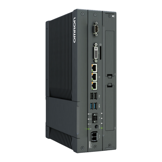
3 Hardware 3-1-2 Base Layer This section shows the component names and functions for the base layer. The base layer houses most of the functionality of the Box PC. Frontside Backside The connector layout and the available components can differ depending on the product configuration. Refer to 1-4 Product Configuration Box PC on page 1-5 for configuration details. -
Page 48: Expansion Layer (Optional)
3 Hardware Item Name Description ID information label Label containing Model ID., LOT No. and other product specific infor- mation. Refer to 1-3 ID Information Label on page 1-4 for label de- tails. Product key The product key for the operating system (optional). The product key is inside the cover of the cooling layer for lotnumbers before 22Z17. -
Page 49: Led Indicators
3 Hardware LED Indicators The Industrial Box PC has LED indicators located at the base layer. These LED indicators provide the current operating status of the Box PC. Models with an Expansion layer have a second row with four LED indicators that have the same func- tion. -
Page 50: Err Led Indicator
3 Hardware 3-2-2 ERR LED Indicator The Error LED (ERR) indicates the presence and type of an error within the Industrial Box PC. Color Status Meaning • Not lit The 24 VDC power is not supplied • No error is present •... -
Page 51: Power Button
3 Hardware Power Button The power button is located at the base layer. The power button is used to manually switch the Box PC ON and OFF. Additional Information • Refer to 6-1 Power ON on page 6-2 for ON details. •... -
Page 52: Connectors
3 Hardware Connectors This section gives an overview of the connectors located at the base layer of the Industrial Box PC. 3-4-1 Power Connector The power connector on the Box PC is used to supply 24 VDC power to the Box PC. The power connector is supplied with the Box PC. -
Page 53: Usb Connectors
3 Hardware Additional Information • Refer to 4-2-2 I/O Connector Specifications on page 4-19 for specifications. • Refer to 5-4-4 Wire the I/O Connector on page 5-36 for wiring details. • Refer to 5-5 Connect on page 5-39 for connection details. 3-4-3 USB Connectors Two USB connectors support USB 2.0 and two USB connectors support USB 3.0 specifications. -
Page 54: Ethernet Connectors
3 Hardware 3-4-4 Ethernet Connectors The Ethernet connectors provide 3 individual Ethernet ports on the Industrial Box PC. Each port offers 10BASE-T/100BASE-TX/1000BASE-T Ethernet speeds. Additional Information • Refer to 4-2-4 Ethernet Connector Specifications on page 4-24 for specifications. • Refer to 5-5 Connect on page 5-39 for connection details. 3-4-5 DVI Connector The DVI interfaces supported on this connector are dependent on the configuration of the Industrial... -
Page 55: Rs-232C Connector (Optional)
3 Hardware 3-4-6 RS-232C Connector (Optional) Depending on the product configuration an optional RS-232C connector is available. Additional Information • Refer to 1-4 Product Configuration Box PC on page 1-5 for configuration details. • Refer to 4-2-7 RS-232C Connector Specifications on page 4-28 for specifications. •... -
Page 56: Ny Monitor Link Connector (Optional)
3 Hardware 3-4-8 NY Monitor Link Connector (Optional) Depending on the product configuration an optional NY Monitor Link connector is available. The NY Monitor Link interface connector connects an OMRON Industrial PC to the OMRON Industrial Monitor. Industrial PC Industrial Monitor Additional Information •... -
Page 57: Ethernet Connector (Optional)
3 Hardware 3-4-9 Ethernet Connector (Optional) Depending on the product configuration an optional Ethernet connector is available. The port offers 10BASE-T/100BASE-TX/1000BASE-T Ethernet speeds. Additional Information • Refer to 1-4 Product Configuration Box PC on page 1-5 for configuration details. • Refer to 4-2-4 Ethernet Connector Specifications on page 4-24 for specifications. •... -
Page 58: Sd Memory Card Slot
3 Hardware SD Memory Card Slot The SD Memory Card slot is located at the base layer. The SD Memory Card slot on the Industrial Box PC accepts SD Memory Cards with the following specifications. • SDHC type (SD 2.0 specification) •... -
Page 59: Cfast Card Slot (Optional)
3 Hardware CFast Card Slot (Optional) Depending on the product configuration an optional CFast Card slot is located at the rear side of the base layer. The CFast Card slot accepts CFast Cards that comply with the CFast 2.0 specification. Additional Information Refer to 3-10-4 CFast Cards on page 3-24 for details. -
Page 60: Drive Bays
3 Hardware Drive Bays The drive bays are located in the expansion layer. The drive bays in the Industrial Box PC accept 2.5 inch Hard Disk Drives (HDD) or Solid State Drives (SSD). Depending on the model one or two drives are supported. Additional Information •... -
Page 61: Pcie Card Slot
3 Hardware PCIe Card Slot The PCI Express (PCIe) Card slot is located in the expansion layer. The PCI Express (PCIe) Card slot of the Industrial Box PC can accept various PCIe Cards for specific hardware needs. The PCIe Card connectors are available behind the cover A and the PCIe Card is mounted in the PCIe drawer B . -
Page 62: Spare Parts
3 Hardware Spare Parts The following spare parts for the Industrial Box PC are available. 3-9-1 Battery One battery is located inside the Box PC. The battery supplies power to the real-time clock. The battery is: • not replaceable for products with a cooling layer that has a non-removable cover. The non-replaceable battery has a lifetime for at least 10 years at 40°C. -
Page 63: Accessory Kit
3 Hardware 3-9-3 Accessory Kit The accessory kit for the Box PC. Model Appearance Specifications NY000-AK00 Accessory Kit containing all accessories sup- plied with the Box PC. • Power connector • I/O connector • Drive bracket for drive installation • 4 mounting screws for drive installation •... -
Page 64: 3-10 Optional Hardware
3 Hardware 3-10 Optional Hardware The following optional hardware is available for the Industrial Box PC. 3-10-1 Mounting Brackets Mounting brackets details are provided below. Model Appearance Bracket type NY000-AB00 Book mount For Model ID: • NYB1C-£1 • NYB1E-£1 • NYB17-£1 •... -
Page 65: Sd Memory Cards
For all Industrial Box PCs 3-10-2 SD Memory Cards SD Memory Card details are provided below. OMRON is not responsible for the operation, performance or write life of any other brand of SD Memo- ry Card. Model Appearance Card type... -
Page 66: Cfast Cards
3 Hardware 3-10-4 CFast Cards CFast Card details are provided below. OMRON is not responsible for the operation, performance, or write life of any other CFast Card. Storage Model Appearance Capacity Details type NY000-AT00 CFast 64 GB Innodisk DECFA-64GM41BW1DC Card... -
Page 67: Hdd And Ssd Storage Devices
Storage Device Considerations For a storage device that is not an OMRON NY000-A£££ consider the following: • OMRON is not responsible for the operation, performance or write life of any storage device other than those supplied by OMRON. • Test and measure the environmental performance of the intended storage device before actual op- eration, using the SMART monitoring feature of the selected storage device. -
Page 68: Dvi Cables
90 mm 3-10-7 USB Type-A to USB Type-B Cables USB Type-A to USB Type-B cable details are provided below. OMRON is not responsible for the operation or performance of any other brand of USB Type-A to USB Type-B cable. Model Appearance... -
Page 69: Ny Monitor Link Cables
3 Hardware 3-10-8 NY Monitor Link Cables Depending on the installation situation specific cables are recommended for an NY Monitor Link (NYML). Refer to: • NYML Recommendations up to 20 m on page 3-27 for details. • NYML Recommendations up to 100 m on page 3-28 for details. •... - Page 70 3 Hardware NYML Recommendations up to 100 m Patch Cables A with different lengths can be used. Use a DIN rail socket B when connecting patch cables to infrastructures. Use installation cable C inside infrastructures. Max 5 m Max 90 m Max 5 m Infrastructure Monitor...
- Page 71 3 Hardware NYML Recommendations for Custom Cables The following table lists the recommended cables and connectors for custom NY Monitor Link cables. Intra cabinet or Inter cabinet and Item light industrial en- Inter cabinet harsh industrial vironment environment Maximum length 25 m 100 m 100 m...
-
Page 72: Industrial Monitor
Additional Information Refer to the OMRON website for specifications and manuals. 3-10-10 Power Supply Details for the recommended power supply are provided below. OMRON is not responsible for the operation or performance of any other power supply. Model Appearance Specifications S8VK-G£££24... -
Page 73: 3-10-11 Ups
• Refer to 4-1-3 Power Consumption Specifications on page 4-4 for power consumption de- tails. • Refer to the OMRON website for S8BA specifications or to the UPS S8BA User's Manual (Cat. No. U702) for the UPS manual. Note that the power consumption details determine the output current/capacity of your UPS. - Page 74 3 Hardware 3-32 NY-series Industrial Box PC Hardware User's Manual (W553)
-
Page 75: Specifications
Specifications This section provides specifications of the Industrial Box PC. General Specifications ................. 4-2 4-1-1 Dimensions and Weight .................. 4-2 4-1-2 General Electrical Specifications ..............4-3 4-1-3 Power Consumption Specifications ..............4-4 4-1-4 Power Supply Specifications ................4-5 4-1-5 CPU Specifications ..................4-6 4-1-6 Memory Specifications.................. -
Page 76: General Specifications
4 Specifications General Specifications This section provides general specifications of the Industrial Box PC. 4-1-1 Dimensions and Weight The following table provides specification details on dimensions and weights. Model Specifications Model details Mount details Width X Height Z Weight *1 *2 Model ID Depth Y •... -
Page 77: General Electrical Specifications
4 Specifications Model Specifications Model details Mount details Width X Height Z Weight *1 *2 Model ID Depth Y • • NYB2A-£0 Without Expan- Not mounted 282 mm 200 mm 41 mm 2.1 kg • NYB2C-£0 sion layer Book mount 211 mm 2.3 kg 319 mm... -
Page 78: Power Consumption Specifications
46 W Installed drives Drives Power consumption Bay A Refer to 4-1-7 Storage Device Specifications on page 4-11 for Omron drive de- tails. For other drives refer to the applicable specifications for maximum power con- Bay B sumption details. CFast... -
Page 79: Power Supply Specifications
4 Specifications 4-1-4 Power Supply Specifications The minimum power supply requirements depend on the maximum power consumption of the Box PC. Refer to 4-1-3 Power Consumption Specifications on page 4-4 for details. With a UPS installed the minimum power requirements are: Minimum power requirements Model Power supply... -
Page 80: Cpu Specifications
4 Specifications 4-1-5 CPU Specifications This section gives the specifications of the CPUs that are available for the Industrial Box PC. Refer to 1-4 Product Configuration Box PC on page 1-5 for product configuration details. ® ® NY£1C Intel Celeron 2980U CPU Specifications ®... - Page 81 4 Specifications ® ® NY£2A Intel Atom x5-E3940 CPU Specifications ® ® CPU specifications for an Intel Atom x5-E3940 CPU. Item Specifications Cores / Threads 4 / 4 CPU base frequency 1.6 GHz Maximum turbo frequency 1.8 Ghz Cache 2 MB Cooling details Passive cooling (fanless) Graphics controller...
- Page 82 4 Specifications ® ™ NY£35 Intel Core i5-7300U CPU Specifications ® ™ CPU specifications for an Intel Core i5-7300U CPU. Item Specifications Cores / Threads 2 / 4 CPU base frequency 2.6 GHz Maximum turbo frequency 3.5 GHz Cache 3 MB Cooling details Passive cooling (fanless) Graphics controller...
-
Page 83: Memory Specifications
4 Specifications 4-1-6 Memory Specifications This section provides the memory specifications of the Industrial Box PC. DDR4 ECC The following table provides specification details of the DDR4 memory. Model Specifications Item 8 GB 16 GB Memory configuration 2 x 4 GB 2 x 8 GB Memory type DDR4 ECC... - Page 84 4 Specifications DDR3L Non-ECC The following table provides specification details of the DDR3L memory. Model Specifications Item 2 GB 4 GB 8 GB 16 GB Memory configuration 1 x 2 GB 1 x 4 GB 2 x 4 GB 2 x 8 GB Memory type DDR3L Non-ECC Package memory for-...
-
Page 85: Storage Device Specifications
4 Specifications 4-1-7 Storage Device Specifications This section provides the specifications of the storage devices. Hard Disk Drive Specifications Specifications for the Hard Disk Drive (HDD) are provided in the table below. Model Specifications Item 320 GB 500 GB 1 TB NY000-AH00 NY000-AH01 NY000-AH02... - Page 86 4 Specifications Solid State Drive Specifications Specifications for the Solid State Drive (SSD) are provided in the table below. Model Specifications Item 32 GB 64 GB 128 GB 500 GB NY000- NY000- NY000- NY000- NY000- NY000- NY000- Model AS00 AS01 AS03 AS06 AS02...
- Page 87 4 Specifications CFast Card Specifications Specifications for the CFast Drive are provided in the table below. Model Specifications Item 64 GB 128 GB 256 GB NY000-AT00 NY000-AT01 NY000-AT02 Model Type iMLC Max. power consumption 0.9 W Max. sequential 530 MB/s read speed Max.
-
Page 88: Pcie Card Specifications
4 Specifications 4-1-8 PCIe Card Specifications The PCI Express (PCIe) Card slot of the Industrial Box PC accepts various cards for specific hardware needs. Ensure that, according to the PCIe hardware specifications, the indent A is present in the PCIe Card. The PCIe Card specifications depend on the CPU and thus on the product configuration. - Page 89 4 Specifications NY£1E-£1 PCIe Card Slot Specifications ® ® The table below provides PCIe Card slot details for Industrial Box PCs with an Intel Xeon E3-1515M v5 CPU. Item Specifications Configuration X4 (4 lanes) up to Gen 3 Card height Standard height cards, 4.20 inches (106.7 mm) Card length Half-length cards, 6.6 inches (167.65 mm)
- Page 90 4 Specifications NY£25-£1 PCIe Card Slot Specifications ® ™ The table below provides PCIe Card slot details for Industrial Box PCs with an Intel Core i5-4300U CPU. Item Specifications Configuration X1 (1 lane) up to Gen 2 Card height Standard height cards, 4.20 inches (106.7 mm) Card length Half-length cards, 6.6 inches (167.65 mm) Power consumption...
-
Page 91: Bracket Specifications
4 Specifications 4-1-9 Bracket Specifications The metal mounting brackets mount your Box PC and they are the connection for the functional ground. Use metal screws with a diameter of 4 mm or 5 mm to mount the brackets. Mounting screw locations for book mount and wall mount orientation: Product Dimen- Model Drill Specifications... -
Page 92: Connector Specifications
4 Specifications Connector Specifications This section provides the Connector Specifications of the Industrial Box PC. 4-2-1 Power Connector Specifications The power supply connector is locked when inserted to prevent unintentional disconnection. The connector can only be inserted the correct way. The connector is a Phoenix Contact type SPC5/2-STCL-7.62 BK (1711708). -
Page 93: I/O Connector Specifications
4 Specifications Locking and Removing the Power Connector The power connector automatically locks into place when the black part of the connector is held and pushed in. Pushing both orange sliders B towards the end of the connector A will release the lock when remov- ing the connector. - Page 94 4 Specifications I/O Connector Pin Details The pin details of the I/O connector. The pin layout represents the I/O connector on the Box PC. The I/O signals connected must be powered from a power supply which conforms to the SELV stand- ards.
- Page 95 4 Specifications I/O Connector Power Status Output Details This section provides details of the Power Status Output relay. The Power Status Output is a relay between pin 1 and 2 of the I/O Connector. Power ON Power Status Output Operation This section provides power ON details of the Power Status Output operation.
- Page 96 4 Specifications Product ON Shutdown Shutdown Product OFF start finished Closed (ON) Relay Open (OFF) Power supply removed Closed (ON) Relay Open (OFF) Additional Information Refer to 5-4-4 Wire the I/O Connector on page 5-36 for I/O connector wiring details. Lock and Remove the I/O Connector The I/O connector locks into place when the black part of the connector is held and pushed in.
-
Page 97: Usb Connector Specifications
4 Specifications 4-2-3 USB Connector Specifications The Industrial Box PC includes four USB connectors. Two connectors provide version 2.0 perform- ance and two connectors provide version 3.0 performance. Details of the USB interface connectors are provided below. The connector layout represents the USB connectors on the Box PC. Interface Connector Details per Connector •... -
Page 98: Ethernet Connector Specifications
4 Specifications 4-2-4 Ethernet Connector Specifications Details of the RJ45 Ethernet connectors are provided below. The Ethernet connector locks automatically to prevent unintentional disconnection. The set of 3 RJ45 Ethernet connectors is available on all models, the single connector is optional. Ethernet Connector Specification Details Details of the RJ45 Ethernet connectors are provided below. - Page 99 4 Specifications Ethernet Connector LED Indicators Details of the RJ45 Ethernet connectors are provided below. Each connector has LED indicators for speed, link and activity. Item Indicator Color Status Description Link/Act Yellow Not lit No link Link Flashing Link and activity Speed Not lit Not lit...
-
Page 100: Dvi Connector Specifications
4 Specifications 4-2-5 DVI Connector Specifications DVI is the standard video interface for the Box PC. Additional Information • Refer to 4-1-5 CPU Specifications on page 4-6 for graphics controller details. • Refer to 5-4-2 Ground on page 5-26 for grounding details. •... -
Page 101: Dvi-D Connector Specifications
4 Specifications 4-2-6 DVI-D Connector Specifications The optional video interface on the Box PC uses a DVI dual link connector. Item Specification Video interface Digital only Resolution Up to 1920 x 1200 pixels at 60 Hz Type Dual link Maximum DVI cable length Dependent upon connected monitor type and resolution Additional Information •... -
Page 102: Rs-232C Connector Specifications
4-2-8 NY Monitor Link Connector Specifications The optional NY Monitor Link connector connects an OMRON Industrial Monitor with an OMRON In- dustrial PC that has an NY monitor link connector. The NY Monitor Link communication is a combination of video and USB information. - Page 103 4 Specifications Industrial PC Industrial Monitor NY Monitor Link Connector LED Indicators The connector has LED indicators Connected A and Video B . NYML Indica- Item Color Status Description Con- Yellow Not lit Not connected nected Connected USB communication active Video Green Not lit...
-
Page 104: Software Specifications
4 Specifications Software Specifications Refer to NY-series Operating Systems and Software Utilities Manual (Cat. No. W616) for details. 4-30 NY-series Industrial Box PC Hardware User's Manual (W553) -
Page 105: Environmental Specifications
4 Specifications Environmental Specifications This section provides environmental specifications of the Industrial Box PC. 4-4-1 Operation Environment Specifications The following table provides the general environmental specifications for the Industrial Box PC. Item Specifications Ambient operating temperature 0 to 55°C Ambient storage temperature -20 to 70°C Ambient operating humidity 10% to 90% with no condensation... -
Page 106: Temperature And Humidity Specifications
4 Specifications 4-4-2 Temperature and Humidity Specifications The allowed ambient operating temperature and ambient humidity depend on the model, mounting ori- entation, and storage device type. The following sections provide temperature and humidity details and temperature specifications per model. Temperature and Humidity Graphs The maximum ambient operating temperature and ambient humidity are specified per storage device type. - Page 107 4 Specifications • Store the Box PC with a SSD within the general environmental specifications. • Store the Box PC with a HDD within the ambient temperature and humidity ranges as shown in fol- lowing graph. Storage temperature- Storage humidity range temperature-humidity range Temperature [°C]...
- Page 108 4 Specifications NYB1C-£1 Temperature Specifications Ambient operating temperature specifications for model NYB1C-£1. ® ® This Box PC has an Intel Celeron 2980U CPU. Additional Information Refer to 1-4 Product Configuration Box PC on page 1-5 for model details. Storage device type Mounting Orientation HDD 320 GB / 500 GB HDD 1 TB...
- Page 109 4 Specifications NYP17-£1 Temperature Specifications Ambient operating temperature specifications for model NYB17-£1. ® ™ This Box PC has an Intel Core i7-4700EQ CPU. Additional Information Refer to 1-4 Product Configuration Box PC on page 1-5 for model details. Storage device type Mounting Ori- 1 x SSD 1 x entation...
- Page 110 4 Specifications NYB2C-£0 Temperature Specifications Ambient operating temperature specifications for model NYB2C-£0. ® ® This Box PC has an Intel Celeron 3965U CPU. Additional Information Refer to 1-4 Product Configuration Box PC on page 1-5 for model details. Storage device type Mounting Orientation CFast Card Book...
- Page 111 4 Specifications NYB25-£1 Temperature Specifications Ambient operating temperature specifications for model NYB25-£1. ® ™ This Box PC has an Intel Core i5-4300U CPU. Additional Information Refer to 1-4 Product Configuration Box PC on page 1-5 for model details. Storage device type Mounting Ori- 1 x SSD 1 x entation...
- Page 112 4 Specifications NYB35-£1 Temperature Specifications Ambient operating temperature specifications for model NYB35-£1. ® ™ This Box PC has an Intel Core i5-7300U CPU. Additional Information Refer to 1-4 Product Configuration Box PC on page 1-5 for model details. Storage device type Mounting Ori- 1 x SSD 1 x entation...
-
Page 113: Recycling Specifications
4 Specifications 4-4-3 Recycling Specifications The following table provides recycling information for the Industrial Box PC. Part Recycle specifications Battery Chemical waste PCIe Card and other electrical components Electrical waste Precautions for Safe Use Dispose of the product and batteries according to local ordinances as they apply. 4-39 NY-series Industrial Box PC Hardware User's Manual (W553) - Page 114 4 Specifications 4-40 NY-series Industrial Box PC Hardware User's Manual (W553)
-
Page 115: Installation
Installation This section provides all installation details for the Industrial Box PC. Unpack ......................5-2 5-1-1 Unpack Procedure ..................5-2 5-1-2 Items Supplied ....................5-2 Install Options ....................5-5 5-2-1 Install a Drive ....................5-5 5-2-2 Install the PCIe Card..................5-9 Mount...................... -
Page 116: Unpack
5 Installation Unpack This section provides details on how to unpack the Industrial Box PC. 5-1-1 Unpack Procedure Check the package for damage. If there is any visible damage: • Take photos of the package and save them. • Inform your supplier immediately. Open the package. - Page 117 5 Installation Items Supplied with the Industrial Box PC This section describes the items supplied with your Industrial Box PC. • Industrial Box PC • Documentation: • Safety Precautions sheets (English and Japanese) • EU Compliance sheet • Standards and Certifications sheet •...
- Page 118 5 Installation Items Supplied with the Brackets This section describes the items supplied with the brackets for your Industrial Box PC. Additional Information • Refer to 3-10-1 Mounting Brackets on page 3-22 for bracket details. • Refer to 5-3-8 Book Mount Procedure on page 5-24 for book mount installation. •...
-
Page 119: Install Options
5 Installation Install Options This section describes the installable options for the Industrial Box PC. 5-2-1 Install a Drive A drive is a storage device for the Industrial Box PC. Additional Information • Depending on the product configuration 0, 1 or 2 drives can be pre-installed. Refer to 1-4 Product Configuration Box PC on page 1-5 for details. - Page 120 5 Installation Pull the metal shielding cover out of the Box PC. Rotate and then remove the break out part from the drive bracket. Align the connectors of the drive as shown A on the bracket. Then insert the replacement drive in the bracket and insert the 4 mounting screws .
- Page 121 5 Installation Insert the bracket with the drive in the correct bay. Refer to 3-1-3 Expansion Layer (Optional) on page 3-6 for bay details. Ensure the bracket is completely in the Box PC with an extra push. The drive bracket will lock into place when it is fully inserted. Insert the metal shielding cover.
- Page 122 5 Installation Mount the drive cover. The lock lever will click when closed correctly. Finalize the drive installation when the Box PC installation is completed. • For a drive that requires an operating system: 1) Install an operating system 2) Power OFF and then Power ON 3) Ensure the drive is functional and confirm normal operation.
-
Page 123: Install The Pcie Card
5 Installation 5-2-2 Install the PCIe Card Prepare the following items: • The PCIe Card. A PCIe Card is not supplied with the Box PC. Additional Information • Depending on the product configuration a PCIe card can be pre-installed. Refer to 1-4 Product Configuration Box PC on page 1-5 for details. •... - Page 124 5 Installation Grip the Card Clip A on the sides . Pull the middle of the Card Clip to unlock it remove it from the PCIe Drawer. Caution When installing or removing a PCIe card, ensure to grip the Card Clip on the sides to prevent contact with the sharp edges of the sheet metal frame tab.
- Page 125 5 Installation Place the PCIe Card in the PCIe Drawer. Ensure to insert the PCIe Card in the correct opening. Ensure the thin sheet metal frame is positioned between the PCIe Card and the PCIe Drawer to ensure a good conductive contact. Place the Card Clip A in the PCIe Card and PCIe Drawer , grip the Card Clip on the sides and then rotate the Clip...
- Page 126 5 Installation Slide the Card Support so that it supports the side of the PCIe Card. The card should be in small groove so there is support below and above the card. Rotate the Card Support to lock it in place. Insert the PCIe Drawer in the Box PC and then insert the two crosshead screws that hold the PCIe Drawer in place.
- Page 127 5 Installation Remove the PCIe cover if the PCIe Card has external connectors. 1) Push the lock lever 2) Tilt the PCIe cover 3) Remove the PCIe cover The PCIe Card is installed. 5-13 NY-series Industrial Box PC Hardware User's Manual (W553)
-
Page 128: Mount
5 Installation Mount This section describes how to mount the Box PC in either a book or wall orientation inside a control panel. WARNING Ensure that installation and post-installation checks of the product are performed by personnel in charge who possess a thorough understand- ing of the machinery to be installed. -
Page 129: Product Orientation
5 Installation 5-3-2 Product Orientation The Box PC can be mounted in a book A or wall B C orientation. • For book mount there is one allowed orientation A . • For wall mount there are two allowed orientations, horizontally mounted B and vertically mounted Do not install the Box PC in other orientations. - Page 130 5 Installation Provide enough space for good air flow and ensure the following minimum distances are observed around the sides of the Box PC. • Book Mount • Wall Mount in landscape A or portrait B orientation Item Minimum distance 50 mm 100 mm 50 mm...
- Page 131 Box PC. • Do not install the Box PC directly above any heat-generating equipment, such as heaters or transformers. • Do not install the Box PC in a location exposed to direct sunlight. OMRON product OMRON product Natural Cooling ...
-
Page 132: Humidity
5 Installation OMRON product OMRON product Forced Air Circulation Room Cooling Cool the entire room where the control panel is located. Cooler Control panel Room Cooling Low Temperatures The Box PC may not start normally if the temperature is below 0°C when the power is turned ON. -
Page 133: Atmosphere
Installation Location Install the Box PC as far away as possible from high-voltage (600 V or higher) and power devices to ensure safe operation and maintenance. Example of Recommended Equipment Arrangement OMRON product Control panel Control panel High-voltage... - Page 134 • Keep the wiring between the transformer and the Box PC as short as possible, twist the wires well, and keep the wiring separate from high-voltage and power lines. Power circuits Power supply for general operations circuits I/O power supply for Omron product I/O power supply for Omron product Noise Unit power supply for Omron product...
- Page 135 5 Installation Wire External I/O Signal Lines Observe the following points when wiring the external I/O signal lines. • To absorb reverse electromotive force when an inductive load is connected to an output signal, con- nect a surge suppressor near the inductive load in an AC circuit, or connect a diode near the induc- tive load in a DC circuit.
- Page 136 5 Installation • Power lines and signal lines • Input signals and output signals • Analog signals and digital signals • High-level signals and low-level signals • Communications lines and power lines • DC signals and AC signals • High-frequency devices (such as Inverters) and signal lines (communications) ...
- Page 137 Ground of 200 mm 100 Ω or less Example: Separating an OMRON product from Power Lines Wiring Ducts Whenever possible, route the cables and wires through wiring ducts. Install the wiring ducts so that it is easy to route the wires from the Industrial Box PC directly into the duct.
-
Page 138: Book Mount Procedure
5 Installation 5-3-8 Book Mount Procedure Use the following procedure to mount the Industrial Box PC in the book orientation. Additional Information • Refer to 5-4-2 Ground on page 5-26 for grounding details. • Refer to 3-10-1 Mounting Brackets on page 3-22 for the bracket model. To mount the Box PC: The Box PC has on one side light grey circles around the threaded mounting holes. -
Page 139: Wall Mount Procedure
5 Installation 5-3-9 Wall Mount Procedure Use the following procedure to mount the Box PC in the wall orientation. Additional Information • Refer to 5-4-2 Ground on page 5-26 for grounding details. • Refer to 3-10-1 Mounting Brackets on page 3-22 for the bracket model. To mount the Box PC: Mount the Brackets A to the Box PC C with the 6 Phillips screws B supplied with the brack- ets. -
Page 140: Wire
5 Installation Wire This section describes how to wire the Industrial Box PC. 5-4-1 Wiring Warnings and Cautions This section describes the Warnings and Cautions when wiring the Industrial Box PC. WARNING Provide safety measures in external circuits to ensure safety in the sys- tem if an abnormality occurs due to malfunction of the product or due to other external factors affecting operation. - Page 141 5 Installation Caution The product has an internal non-isolated DC power supply. Circuit ground (0 VDC) and frame ground are connected together. When con- necting a non-isolated device or a non-isolated interface to the product, take appropriate actions to avoid communication failures or damage to the mentioned ports.
- Page 142 5 Installation Considerations for Earthing Methods Local potential fluctuations due to lightning or noise occurred by power devices will cause potential fluctuations between ground terminals of devices. This potential fluctuation may result in device mal- function or damage. To prevent this, it is necessary to suppress the occurrence of a difference in elec- trical potential between ground terminals of devices.
- Page 143 5 Installation Equipotential Bonding System Equipotential bonding is an earthing method in which steel frames and building structures, metal ducts and pipes, and metal structures in floors are connected together and make connections to the earth trunk line to achieve a uniform potential everywhere across the entire building. We recommend this earthing method.
- Page 144 5 Installation Star Earthing If the earthing method used for the building is not equipotential bonding or the earthing system is un- known, choose (a) from among the earthing methods given below. a. Connecting devices and noise sources to separate earth electrodes This is an earthing method to separately ground an earth electrode of the device that is connected with a communications cable or other devices and an earth electrode of a high-power device that could be a noise source, such as a motor or inverter.
- Page 145 5 Installation Daisy Chain This is an earthing method to connect the device that is connected with a communications cable, other devices, and a device that could be a noise source using a daisy-chain topology to a common earth electrode. This earthing method is not recommended because the device that could be a noise source may inter- fere electromagnetically with other devices.
- Page 146 5 Installation Ground Connection Details This section provides details about the ground connection. Use the functional ground terminal on the mounting bracket(s) to ground your Industrial Box PC. The washers and nut C are supplied with the bracket(s). Refer to Items Supplied with the Brackets on page 5-4 for details. Book Mount Mount the ground connection wire B to the functional ground terminal A using the washers and nut C .
-
Page 147: Wire The Power Connector
5 Installation Crimp terminals Use crimp terminals with dimensions X = M4 and Y = 8 mm max. 5-4-3 Wire the Power Connector This section describes how to wire the power connector. Precautions for Safe Use • Do not perform a dielectric strength test. •... - Page 148 Maximum AWG according to UL/cUL • Power Supply Connector DC Power Supply The OMRON S8VK-series power supply is recommended for use with the Industrial Box PC. Additional Information • Refer to 3-10-10 Power Supply on page 3-30 for more information.
- Page 149 5 Installation Power Connector Wiring Procedure Use the following procedure to wire the power connector. Ensure the power connector is not connected to the Box PC. 7 mm Remove the sheath from the power supply wires. Precautions for Safe Use Observe the following precautions to prevent broken wires.
-
Page 150: Wire The I/O Connector
5 Installation 5-4-4 Wire the I/O Connector This section describes how to wire the I/O connector. I/O Connector Wiring Materials Use the supplied I/O connector to connect the inputs and outputs to the Industrial Box PC. Recommended I/O conductor sizes for the connector are provided in the table. Wire type Conductor cross-section Solid conductor... - Page 151 5 Installation Description Internal Circuit Details Power ON Input The Power ON Input and the UPS Mode Input are bi-di- rectional and isolated. Each input can be wired as sinking (NPN) or sourcing (PNP). Wire these according to the UPS Mode Input output device connected to the inputs.
- Page 152 5 Installation I/O Connector Wiring Procedure Use the following procedure to wire the I/O connector. Ensure the I/O connector is not connected to the Box PC. 7 mm Remove the sheath from the wires. Precautions for Safe Use Observe the following precautions to prevent broken wires. •...
-
Page 153: Connect
5 Installation Connect This section describes how to connect the Industrial Box PC. 5-5-1 Connector Identification An overview of the connectors of the base layer. Item Name Description Power connector Lockable power connector I/O connector 2 inputs (UPS signal and power OFF control) and 1 output (power state) USB 3.0 connector 2 USB 3.0 connectors... -
Page 154: Connection Procedure
5 Installation 5-5-2 Connection Procedure Use the following procedure to connect the Industrial Box PC. Ensure the Box PC is securely fastened to the mounting surface. Ensure the mounted Box PC can be connected to power and peripheral devices. Remove dust covers where applicable and store them in a safe place. - Page 155 5 Installation Connect the I/O connector. Hold the black part A when inserting the connector, this enables the auto-locking mechanism. Do not tilt the orange levers B because this will unlock the connector. Connect an external monitor such as the Industrial Monitor. Connect the monitor to the DVI connector and tighten the fastening screws or use the optional NYML connector.
-
Page 156: Initial Power On
Connect a keyboard and/or a mouse. Additional Information • If using an OMRON Industrial Monitor this may not be required because it has touch function- ality. • Do not connect additional storage devices before the installation of the operating system completed. - Page 157 The Box PC is ON and if an operating system is installed it will start. Precautions for Safe Use Always use the SMART monitoring feature for storage devices that do not comply to the Omron Storage Device Specifications. Monitor the operating temperature and vibrations to ensure they stay within the environmental specifications of the storage device.
-
Page 158: Windows Startup First Time
Select the language carefully, the selected system language can not be changed. • Legal stuff like license agreements • Windows 10: Select Accept to accept the combined Windows and OMRON license agree- ments. • Windows 7: Select Accept separately for Windows and for the OMRON utilities. - Page 159 5 Installation Additional Information • Use the Industrial Monitor Utility to adjust the display and/or the connected OMRON Industrial Monitor. • Verify that the Box PC is responding to finger touches on the touchscreen of the product. Install any third party software and drivers that may be required for your applications.
-
Page 160: Install Software
5 Installation Install Software Install applicable software and activate Windows. Additional Information Refer to NY-series Operating Systems and Software Utilities Manual (Cat. No. W616) for de- tails. 5-46 NY-series Industrial Box PC Hardware User's Manual (W553) -
Page 161: Connect Ups
The Box PC can automatically start up again when the pow- er is restored. To connect the Box PC to the OMRON S8BA UPS use one of the following two options: • The USB connector and Power Attendant Lite Utility Software. -
Page 162: Connect Ups Using The Usb Connector
• Drivers for the S8BA UPS from this OMRON website. • Installation files and manual for the Power Attendant Lite Utility from this OMRON website. • Installation files and manual for the UPS Settings Utility (Windows only) from this OMRON web- site. - Page 163 5 Installation UPS (S8BA) 24 VDC Power Supply (S8VK) Output Industrial PC Input AC (L) 24 VDC AC (N) 0 VDC Refer to the UPS S8BA User's Manual (Cat. No. U702) for details. Refer to 5-4-3 Wire the Power Connector on page 5-33 for wiring details. Supply power to the Power Supply.
-
Page 164: Connect Ups Using The I/O Connector
• For all other Box PCs following software can be downloaded: • Drivers for the S8BA UPS from this OMRON website. • Installation files and manual for the UPS Settings Utility (Windows only) from this OMRON web- site. Precautions for Safe Use •... - Page 165 5 Installation For Box PCs that do not have Windows pre-installed: Download the above mentioned soft- ware. Wire the S8BA UPS. 1) Wire the input of the UPS to the output of the Power Supply. 2) Wire the output of the UPS to the power connector of the Box PC. 3) Ground the UPS.
- Page 166 5 Installation • Start the Box PC • Start applications • Create a power interruption • Monitor the shutdown sequence and confirm a correct shutdown sequence The UPS is connected and configured. The Box PC will shut down properly in case of a power supply interruption and restart automatically when the power is restored.
-
Page 167: Create Backup And Repair Data
5 Installation Create Backup and Repair Data Ensure the operating system, software and data can always be restored when required. There are different software tools to create a backup and repair data. Select the Backup and Repair procedure or procedures that are most suitable for your situation. Precautions for Correct Use Refer to NY-series Operating Systems and Software Utilities Manual (Cat. - Page 168 5 Installation 5-54 NY-series Industrial Box PC Hardware User's Manual (W553)
- Page 169 Operating Procedures This section provides the operating procedures for the Industrial Box PC. Power ON ......................6-2 6-1-1 Power ON Using the Power Button ..............6-2 6-1-2 Power ON Using the Power ON/OFF Input ............ 6-2 6-1-3 Auto Power ON....................6-2 Power OFF ......................
-
Page 170: Power On
6 Operating Procedures Power ON This section provides Power ON details. 6-1-1 Power ON Using the Power Button Start condition: Power is supplied to the Box PC and the Box PC is OFF. Press the power button and release within 1 second. Refer to 3-3 Power Button on page 3-9 for the power button location. -
Page 171: Power Off
6 Operating Procedures Power OFF This section provides Power OFF details. Before following power OFF procedures below, check that the Industrial Box PC is ON by examining the LED indicators on the Box PC. 6-2-1 Power OFF Using the Power Button Ensure all programs are closed. -
Page 172: Power Off Using The Power On/Off Input
6 Operating Procedures 6-2-3 Power OFF Using the Power ON/OFF Input Ensure all programs are closed. If required, close all active programs. Supply a 24 VDC signal to the Power ON/OFF Input (pins 3 and 4) of the I/O connector. The input signal must remain ON for a minimum of 60 ms and a maximum of 750 ms to be correctly detected by the Industrial Box PC. -
Page 173: React To Product Messages
6 Operating Procedures React to Product Messages The Industrial Box PC uses the Industrial PC Tray Utility icon A in the system tray area B of Win- dows to present Warnings and Errors. Check the Industrial PC Tray Utility icon for a Warning or Error symbol. A Warning or Error symbol displayed on the Industrial PC Tray Utility icon indicates a product mes- sage. -
Page 174: React To Windows Messages
6 Operating Procedures React to Windows Messages Windows uses the Windows Action Center icon A in the system tray area B of Windows to present Warnings and Errors. Windows 10 Windows 7 Check the Windows Action Center icon for a Warning or Error symbol. A Warning or Error symbol displayed on the Windows Action Center icon indicates a Windows mes- sage. -
Page 175: Maintenance
Maintenance This section provides an overview of all maintenance tasks for the Industrial Box PC. Preventive Maintenance ................7-2 7-1-1 Preventive Maintenance Schedule ..............7-2 7-1-2 Clean the Box PC ................... 7-3 Corrective Maintenance................. 7-4 7-2-1 Warning and Error Messages ................. 7-4 7-2-2 Remove the Cover.................. -
Page 176: Preventive Maintenance
• Refer to 3-2 LED Indicators on page 3-7 for LED details. Monitor storage devices that do not Refer to Storage Device Considerations on page 3-25 for details. comply to the Omron specifications Weekly Reference Clean the Box PC Refer to 7-1-2 Clean the Box PC on page 7-3 for cleaning details. -
Page 177: Clean The Box Pc
7 Maintenance When the Industrial Box PC is Reference not powered for 6 months For a cooling layer with removable Refer to 7-2-3 Replace the Fan Unit on page 7-7 to replace the Fan cover and active cooling: Unit. • Confirm both fans rotate immedi- ately after Power ON. -
Page 178: Corrective Maintenance
WARNING Do not attempt to disassemble, repair, or modify the product in any way. Doing so may result in malfunction or fire. Contact your local OMRON representative if the corrective maintenance actions did not solve the problem. 7-2-1 Warning and Error Messages Warning and Error messages are provided by the Industrial Box PC when there is a potential problem that may cause downtime. - Page 179 7 Maintenance Windows did not find anti-virus software on this computer. • Windows Update (Important) windows Update is not set up for this computer. • Set up backup Your files are not being backed up. Additional Information Refer to 6-4 React to Windows Messages on page 6-6 for details. Windows Pop Up Window Windows Pop Up windows provide information on Windows issues.
-
Page 180: Remove The Cover
7 Maintenance 7-2-2 Remove the Cover Applicable for products with a cooling layer that has a removable Cover. The Cover of the cooling layer provides access to the following items. • Battery • Fan Unit (applies to products with active cooling) The inside of the Cover contains a label with the battery replacement date. -
Page 181: Replace The Fan Unit
7 Maintenance 7-2-3 Replace the Fan Unit The fans are mounted in the Fan Unit. Use the following procedure to replace the Fan Unit. Precautions for Safe Use If the replacement Fan Unit has been stored over 6 months then check the performance of the Fan Unit after replacement. - Page 182 7 Maintenance Replace the complete Fan Unit. 1) Push the lever to unlock the Fan Unit. 2) Lift the lever to tilt the Fan Unit. 3) Remove the complete Fan Unit. Insert the new Fan Unit in the Box PC. Ensure the end of the Fan Unit A is positioned under the fan guide B .
-
Page 183: Replace The Battery
7 Maintenance 7-2-4 Replace the Battery Applicable for products with a cooling layer that has a removable cover. Precautions for Safe Use • The Battery may leak, rupture, heat, or ignite. Never short-circuit, charge, disassemble, heat, or incinerate the Battery or subject it to strong shock. •... - Page 184 7 Maintenance Lift the battery from the compartment. Disconnect the battery from the battery connector Connect the new battery to the battery connector. Place the new battery in the Box PC. Ensure the wires are at the side of the battery and not on top of the battery. If the wires are on top of the battery this might make closing and opening the cover more difficult.
-
Page 185: Replace A Drive
7 Maintenance 7-2-5 Replace a Drive Use the following procedure to replace a drive. Prepare the new drive. Additional Information • Refer to 1-4 Product Configuration Box PC on page 1-5 for the installed drive model. • Refer to 3-10-5 HDD and SSD Storage Devices on page 3-25 for the available drive models. •... - Page 186 7 Maintenance Pull the metal shielding cover out of the Box PC. Insert the drive cover in the drive bracket bay and move it down so that it locks in the drive bracket. 7-12 NY-series Industrial Box PC Hardware User's Manual (W553)
- Page 187 7 Maintenance Remove the drive bracket from the Box PC using the drive cover. Remove the 4 mounting screws and then remove the drive from the drive bracket. 7-13 NY-series Industrial Box PC Hardware User's Manual (W553)
- Page 188 7 Maintenance Align the connectors of the replacement drive as shown A on the bracket. Then insert the re- placement drive in the bracket and insert the 4 mounting screws . Tighten these screws with a torque of 0.35 N·m. Insert the bracket with the replacement drive into the correct bay of the Box PC.
- Page 189 7 Maintenance Insert the metal shielding cover. Mount the drive cover. The lock lever will click when closed correctly. Restore the drive data. The drive is replaced. 7-15 NY-series Industrial Box PC Hardware User's Manual (W553)
-
Page 190: Replace The Pcie Card
7 Maintenance 7-2-6 Replace the PCIe Card Use the following procedure to replace the PCIe Card. Prepare: • The PCIe Card Additional Information Refer to 4-1-8 PCIe Card Specifications on page 4-14 for PCIe specifications. • The PCIe Card mounting materials: Card Clip and Card Support These are supplied with the Industrial Box PC. - Page 191 7 Maintenance Push the notch at the bottom of the Card Support up and rotate the Card Support. Slide the Card Support away from the card to create space and to remove it. Grip the Card Clip A on the sides .
- Page 192 7 Maintenance Remove the PCIe Card from the PCIe Drawer. The PCIe Card is now removed. Place the replacement PCIe Card in the PCIe Drawer. Ensure the PCIe Card is inserted into the correct opening. 7-18 NY-series Industrial Box PC Hardware User's Manual (W553)
- Page 193 7 Maintenance Place the Card Clip A in the PCIe Card and PCIe Drawer , grip the Card Clip on the sides and then rotate the Clip to lock it in place. Caution When installing or removing a PCIe card, ensure to grip the Card Clip on the sides to prevent contact with the sharp edges of the sheet metal frame tab.
- Page 194 7 Maintenance Insert the PCIe Drawer in the Box PC and then insert the two crosshead screws that hold the PCIe Drawer in place. Remount the Box PC. Confirm normal operation. The PCIe Card is replaced. 7-20 NY-series Industrial Box PC Hardware User's Manual (W553)
-
Page 195: Replace The Cfast Card
7 Maintenance 7-2-7 Replace the CFast Card Use the following procedure to replace the CFast Card. Prepare the new CFast Card. Additional Information • Refer to 1-4 Product Configuration Box PC on page 1-5 for the installed CFast Card model. •... - Page 196 7 Maintenance Insert the replacement CFast Card A into the slot of the Box PC. Ensure the CFast Card A is completely in the Box PC with an extra push using the CFast Card slot cover. If the CFast Card can not go in completely then the CFast Card orientation is incorrect. Re- move the CFast Card, turn it upside down and reinsert it.
- Page 197 7 Maintenance Finalize the drive replacement. If the Box PC has a Windows operating system and the storage drive is not visible in Windows then the drive needs to be allocated. The CFast Card is replaced. 7-23 NY-series Industrial Box PC Hardware User's Manual (W553)
- Page 198 7 Maintenance 7-24 NY-series Industrial Box PC Hardware User's Manual (W553)
- Page 199 Appendices BIOS ....................... A-2 A-1-1 BIOS Overview ....................A-2 A-1-2 BIOS for 4 generation CPUs ................ A-4 A-1-3 BIOS for 6 generation CPUs ..............A-12 A-1-4 BIOS for 7 generation CPUs ..............A-30 A-1-5 BIOS for Atom CPUs ..................A-46 DVI Connector Pin Details ................
-
Page 200: A-1 Bios
Appendices A-1 BIOS This section provides the BIOS information of the Industrial Box PC. WARNING Changing BIOS information is only allowed for the engineer in charge that possesses a thorough understanding of the BIOS settings because it can change the behavior of the product. A-1-1 BIOS Overview The BIOS contains settings that influence the behavior of the Industrial Box PC. - Page 201 Appendices BIOS Navigation and Function Keys The right part of the BIOS screens is divided in two parts. Top part. Provides additional information on selected screens or parameters. Bottom part. Provides information on Keys. • àß : Select Screen Changed between different BIOS pages. •...
-
Page 202: Bios For 4 Th Generation Cpus
Appendices A-1-2 BIOS for 4 generation CPUs The BIOS settings for 4 generation CPUs. The BIOS is divided in the pages Main, Advanced, Chipset, Boot, Security and Save & Exit. BIOS - Main The main setup screen gives platform information about the BIOS, Board Information, Firmware Revi- sion, MAC Addresses and information about the number of Boots and the Running Time. - Page 203 Appendices BIOS - Advanced This section provides Advanced BIOS information for 4 generation CPUs. Changeable BIOS Advanced parameters and their factory default values: Item Default / Remark Disabled Machine Control Graphics Primary Graphics Device Auto Internal Graphics Device Auto IGD Pre-Allocated Graphics Memory IGD Total Graphics Memory 256M Primary IGD Boot Display Device...
- Page 204 Appendices Item Default / Remark PCI & PCI Express PCI Express Gen 2 Set- Completion Timeout Default tings ARI Forwarding Disabled AtomicOp Requester En- Disabled able AtomicOp Egress Block- Disabled IDO Request Enable Disabled IDO Completion Enable Disabled LTR Mechanism Enable Disabled End-End TLP Prefix Disabled...
- Page 205 Appendices Item Default / Remark PCI & PCI Express GbE Channel 0 PCI Express Port 0 Enabled ASPM Disabled GbE Channel 1 PCI Express Port 1 Enabled ASPM Disabled PCI Express Port 0, 1 (x4 PEG1 Speed Auto PEG1 ASPM Disabled Gen3) PEG1 De-emphasis Con-...
- Page 206 Appendices Item Default / Remark CPU Information Display of CPU parame- ters Set Boot Freq Ratio Enabled *2 *1 Hyper-Threading Active Processor Cores Limit CPUID Maximum Disabled Execute Disable Bit Enabled Intel Vitalization Technology Enabled Hardware Prefetcher Enabled Adjacent Cache Line Prefetch Enabled Enabled *2 *1...
- Page 207 Appendices Item Default / Remark SMART Settings Disabled Smart Self Test UEFI Network Stack UEFI Network Stack Disabled NVMe Configuration No NVME device found Intel® Ethernet NIC Configuration Link Speed Auto Negotiated Connection I218-LM - Wake On LAN Enabled Unique MAC Address Blink LEDs ®...
- Page 208 Appendices BIOS - Boot Provides Boot information and configuration settings. Changeable BIOS Boot parameters and their factory default values: Item Default / Remark Quiet Boot Disabled Setup Prompt Timeout Bootup NumLock State Battery Support Auto (Battery Manager) Remain Off Power Loss Control CSM &...
- Page 209 Appendices BIOS - Security Provides security information like BIOS Password and HDD information. WARNING Security setting adjustments should only be performed by the engineer in charge that possesses a thorough understanding of the security set- tings. Selecting non-recommended security settings can put your sys- tem at risk.
-
Page 210: Bios For 6 Th Generation Cpus
Appendices A-1-3 BIOS for 6 generation CPUs The BIOS settings for 6 generation CPUs. The BIOS is divided in the pages Main, Advanced, Chipset, Security, Boot and Save&Exit. BIOS - Main The main setup screen gives platform information about the BIOS, Board Information, Firmware Revi- sion, MAC Addresses and information about the number of Boots and the Running Time. - Page 211 Appendices BIOS - Advanced This section provides Advanced BIOS information for 6 generation CPUs. Changeable BIOS Advanced parameters and their factory default values: Item Default / Remark Intel RC ACPI Settings PTID Support Disabled PECI Access Method Direct I/O Native PCI Express Support Enabled Native ASPM Disabled...
- Page 212 Appendices Item Default / Remark Power & Performance CPU - Power Manage- Boot performance mode Max Non-Turbo Per- ment Control formance Intel ® SpeedStep ™ Enabled Race To Halt (RTH) Enabled Intel ® Speed Shift Technology Enabled HDC Control Enabled Turbo Mode Enabled CPU - Power Management Control /View/Configure Turbo Options...
- Page 213 Appendices Item Default / Remark Power & Performance CPU - Power Management Control / CPU VR Settings / System Agent VR Settings CPU - Power Management Control / CPU VR Settings / Core/IA VR Settings CPU - Power Management Control / CPU VR Settings / GT-UnSliced VR Settings CPU - Power Management Control / CPU VR Settings / GT-Sliced VR Settings VR Config Enable Enabled...
- Page 214 Appendices Item Default / Remark PCH-FW Configuration Comms Hub Support Disabled JHI Support Disabled Core Bios Done Message Enabled Firmware Update Con- Me FW Image Re-Flash Disabled figuration PTT Configuration TPM Device Selection dTPM ME Debug Configura- HECI Timeouts Enabled tion Force ME DID Init Status Disabled...
- Page 215 Appendices Item Default / Remark Hardware Health Moni- Fan PWM Frequency Mode High Frequency toring Fan PWM Frequency (kHz) Pulses Per Revolution Default Fan Speed Automatic Fan Speed Control Enabled Fan Control Temperature CPU Temperature Lower Temperature Limit 50 C Upper Temperature Limit 80 C Minimum Fan Speed...
- Page 216 Appendices Item Default / Remark CSM & Option ROM CSM Support Enabled Control Gate A20 Active Upon Request Option ROM Messages Force BIOS INT19 Trap Response Immediate Boot Option Filter UEFI and Legacy PXE Option ROM Launch Policy UEFI ROM Only Storage Option ROM Launch Policy UEFI ROM Only Video Option ROM Launch Policy...
- Page 217 Appendices BIOS - Chipset Provides BIOS Chipset settings for 6 generation CPUs. Changeable BIOS Chipset parameters and their factory default values: Item Default / Remark Processor Memory Configuration / Memory Thermal Configuration Refer to Memory Ther- (Integrated mal Configuration on Components) page A-25 for details.
- Page 218 Appendices Item Default / Remark Processor Memory Configuration / Memory Training Algorithms (Integrated Write Voltage Centering 2D Enabled Components) Read Voltage Centering 2D Enabled Late Command Training Enabled Round Trip Latency Enabled Turn Around Timing Training Enabled Rank Margin Tool Disabled Memory test Disabled...
- Page 219 Appendices Item Default / Remark Processor Memory Configuration Force Single Rank Disabled (Integrated Memory Remap Enabled Components) Time Measure Disabled DLL Weak Lock Support Enabled Pwr Down Idle Timer Mrc Fast Boot Enabled Lpddr Mem WL Set Set B EV Loader Disabled EV Loader Delay Enabled...
- Page 220 Appendices Item Default / Remark Processor Stop Grant Configuration Auto (Integrated VT-d Enabled Components) CHAP Device Disabled Thermal Device Disabled GMM Device Enabled CRID Support Disabled Above 4GB MMI BIOS assignment Disabled X2APIC Opt Out Disabled eDRAM Mode eDRAM HW Mode Platform Controller Isolate SMBus Segments Always...
- Page 221 Appendices Item Default / Remark Platform Controller SATA And RST Con- Serial ATA Port 1 Hub (PCH) figuration SATA Port Enabled Hot Plug Disabled Spin Up Device Disabled SATA Device Type Hard Disk Drive Topology Unknown SATA Port 1 DevSlp Disabled DITO Configuration Disabled...
- Page 222 Appendices Item Default / Remark Platform Controller Enable TCO Timer Disabled Hub (PCH) Pcie P11 SSC Auto IOAPIC 24-119 Entries Enabled Unlock PCH P2SB Disabled Flash Protection Range Registers (FPRR) Disabled SPD Write Disable TRUE ChipsetInit HECI Message Enabled Bypass ChipsetInit sync reset Disabled A-24 NY-series Industrial Box PC Hardware User's Manual (W553)
- Page 223 Appendices BIOS - Chipset Details This section provides BIOS Chipset details for 6 generation and 7 generation CPUs. Memory Thermal Configuration Provides BIOS Chipset details for the submenu Processor / Memory Configuration / Memory Ther- mal Configuration /. Changeable BIOS Memory Thermal Configuration parameters and their factory default values: Item Default / Remark Memory Power and...
- Page 224 Appendices PCI Express Port Provides BIOS Chipset details for the submenu Platform Controller Hub / PCI Express Configura- tion / PCI Express Port. Changeable BIOS PCI Express Port parameters and their factory default values: Item Default / Remark PCI Express Port Enabled Topology CPU specific...
- Page 225 Appendices BIOS - Security Provides security information like BIOS Password and HDD information. WARNING Security setting adjustments should only be performed by the engineer in charge that possesses a thorough understanding of the security set- tings. Selecting non-recommended security settings can put your sys- tem at risk.
- Page 226 Appendices BIOS - Boot Provides Boot information and configuration settings. Changeable BIOS Boot parameters and their factory default values: Item Default / Remark Quiet Boot Disabled Setup Prompt Timeout Bootup NumLock State Remain Off Power Loss Control AT Shutdown Mode Hot S5 Enter Setup If No Boot Device Enable Popup Boot Menu...
- Page 227 Appendices BIOS - Save & Exit Provides the possibility to leave the BIOS with or without saving changes and to create or restore a set of User Defaults. Save & Exit Parameters: Disabled. • Save Changes and Exit Changed settings are saved and the Operating System starts with the changed settings. •...
-
Page 228: Bios For 7 Th Generation Cpus
Appendices A-1-4 BIOS for 7 generation CPUs The BIOS settings for 7 generation CPUs. The BIOS is divided in the pages Main, Advanced, Chipset, Security, Boot and Save&Exit. BIOS - Main The main setup screen gives platform information about the BIOS, Board Information, Firmware Revi- sion, MAC Addresses and information about the number of Boots and the Running Time. - Page 229 Appendices BIOS - Advanced This section provides Advanced BIOS information for 7 generation CPUs. Changeable BIOS Advanced parameters and their factory default values: Item Default / Remark Intel RC ACPI Settings PTID Support Disabled PECI Access Method Direct I/O Native PCI Express Support Enabled Native ASPM Disabled...
- Page 230 Appendices Item Default / Remark Power & Performance CPU - Power Manage- Boot performance mode Max Non-Turbo Per- ment Control formance Intel ® SpeedStep ™ Enabled Race To Halt (RTH) Enabled Intel ® Speed Shift Technology Enabled HDC Control Enabled Enabled Turbo Mode CPU - Power Management Control /View/Configure Turbo Options...
- Page 231 Appendices Item Default / Remark Power & Performance GT - Power Manage- Maximum GT frequency Default Max Frequen- ment Control PCH-FW Configuration Comms Hub Support Disabled JHI Support Disabled Core Bios Done Message Enabled Firmware Update Con- Me FW Image Re-Flash Disabled figuration PTT Configuration...
- Page 232 Appendices Item Default / Remark Platform Settings UCSI Retry Workaround Disabled Firmware Configuration Test PS2 Keyboard and Mouse Enabled Pmic Vcc IO Level Disabled Pmic Vddq Level Disabled SLP_SO# VM Disabled Power Sharing Manager Disabled Wireless device Disabled Enable Wireless Charge Support Disabled Enable FFU support Disabled...
- Page 233 Appendices Item Default / Remark UEFI Network Stack UEFI Network Stack Disabled CSM & Option ROM CSM Support Enabled Control Gate A20 Active Upon Request Option ROM Messages Force BIOS INT19 Trap Response Immediate Boot Option Filter UEFI and Legacy PXE Option ROM Launch Policy UEFI ROM Only Storage Option ROM Launch Policy...
- Page 234 Appendices BIOS - Chipset This section provides Chipset information for 7 generation CPUs. Changeable BIOS Chipset parameters and their factory default values: Item Default / Remark Processor Memory Configuration / Memory Thermal Configuration Refer to Memory Ther- (Integrated mal Configuration on Components) page A-25 for details.
- Page 235 Appendices Item Default / Remark Processor Memory Configuration / Memory Training Algorithms (Integrated Write Voltage Centering 2D Enabled Components) Read Voltage Centering 2D Enabled Late Command Training Enabled Round Trip Latency Enabled Turn Around Timing Training Enabled Rank Margin Tool Disabled Memory test Disabled...
- Page 236 Appendices Item Default / Remark Processor Memory Configuration Force Single Rank Disabled (Integrated Memory Remap Enabled Components) Time Measure Disabled DLL Weak Lock Support Enabled Pwr Down Idle Timer Mrc Fast Boot Enabled Lpddr Mem WL Set Set B EV Loader Disabled EV Loader Delay Enabled...
- Page 237 Appendices Item Default / Remark Platform Controller Isolate SMBus Segments Always Hub (PCH) PCI Express Configu- PCI Express Clock Gating Disabled ration Legacy IO Low Latency Disabled DMI Link ASPM PCH Side Disabled Port8xh Decode Disabled Peer Memory Write Enable Disabled Compliance Test Mode Disabled...
- Page 238 Appendices Item Default / Remark Platform Controller SATA And RST Con- Hot Plug Disabled Hub (PCH) figuration Spin Up Device Disabled SATA Device Type Hard Disk Drive Topology Unknown SATA Port 2 DevSlp Disabled DITO Configuration Disabled USB Configuration XHCI Disable Compliance Mode False xDCI Support Disabled...
- Page 239 Appendices BIOS - Chipset Details This section provides BIOS Chipset details for 6 generation and 7 generation CPUs. Memory Thermal Configuration Provides BIOS Chipset details for the submenu Processor / Memory Configuration / Memory Ther- mal Configuration /. Changeable BIOS Memory Thermal Configuration parameters and their factory default values: Item Default / Remark Memory Power and...
- Page 240 Appendices PCI Express Port Provides BIOS Chipset details for the submenu Platform Controller Hub / PCI Express Configura- tion / PCI Express Port. Changeable BIOS PCI Express Port parameters and their factory default values: Item Default / Remark PCI Express Port Enabled Topology CPU specific...
- Page 241 Appendices BIOS - Security Provides security information like BIOS Password and HDD information. WARNING Security setting adjustments should only be performed by the engineer in charge that possesses a thorough understanding of the security set- tings. Selecting non-recommended security settings can put your sys- tem at risk.
- Page 242 Appendices BIOS - Boot Provides Boot information and configuration settings. Changeable BIOS Boot parameters and their factory default values: Item Default / Remark Quiet Boot Disabled Setup Prompt Timeout Bootup NumLock State Remain Off Power Loss Control AT Shutdown Mode Hot S5 Enter Setup If No Boot Device Enable Popup Boot Menu...
- Page 243 Appendices BIOS - Save & Exit Provides the possibility to leave the BIOS with or without saving changes and to create or restore a set of User Defaults. Save & Exit Parameters: Disabled. • Save Changes and Exit Changed settings are saved and the Operating System starts with the changed settings. •...
-
Page 244: A-1-5 Bios For Atom Cpus
Appendices A-1-5 BIOS for Atom CPUs The BIOS settings for Atom CPUs. The BIOS is divided in the pages Main, Advanced, Chipset, Security, Boot and Save&Exit. BIOS - Main The main setup screen gives platform information about the BIOS, Board Information, Firmware Revi- sion, MAC Addresses and information about the number of Boots and the Running Time. - Page 245 Appendices BIOS - Advanced This section provides Advanced BIOS information for a Box PC with an Atom CPU. Changeable BIOS Advanced parameters and their factory default values: Item Default / Remark Trusted Computing Security Device Support Enabled SHA-1 PCR Bank Enabled SHA256 PCR Bank Enabled...
- Page 246 Appendices BIOS - Chipset This section provides Chipset information for a Box PC with an Atom CPU. Changeable BIOS Chipset parameters and their factory default values: Item Default / Remark Processor Max TOLUD 2 GB (Integrated Above 4GB MMIO BIOS assignment Disabled Components) Extention Graphic...
- Page 247 Appendices BIOS - Security Provides security information like BIOS Password and HDD information for a Box PC with an Atom CPU. WARNING Security setting adjustments should only be performed by the engineer in charge that possesses a thorough understanding of the security set- tings.
- Page 248 Appendices BIOS - Boot Provides Boot information and configuration settings for a Box PC with an Atom CPU. Changeable BIOS Boot parameters and their factory default values: Item Default / Remark Setup Prompt Timeout Bootup NumLock State Enter Setup If No Boot Device Enable Popup Boot Menu Boot Priority Selection Type Based...
- Page 249 Appendices BIOS - Save & Exit Provides the possibility to leave the BIOS with or without saving changes and to create or restore a set of User Defaults. Save & Exit Parameters: Disabled. • Save Changes and Exit Changed settings are saved and the Operating System starts with the changed settings. •...
-
Page 250: A-2 Dvi Connector Pin Details
Appendices A-2 DVI Connector Pin Details This section provides the pin details for the DVI-I connector and for the optional DVI-D connector. A-2-1 DVI-I Connector Pin Details Pin details of the DVI-I connector. C1 C2 C3 C4 The pin layout represents the DVI-I connector on the Industrial Box PC. Pin numbers increase from left to right for every row. -
Page 251: A-2-2 Dvi-D Connector Pin Details
Appendices Signal Name Function TMDS clock+ Digital clock+ TMDS clock− Digital clock− Analog red Depending on the product configuration Analog green Depending on the product configuration Analog blue Depending on the product configuration Analog horizontal sync Depending on the product configuration 0 VDC Depending on the product configuration For models NY£17 and NY£1E. - Page 252 Appendices Signal Name Function +5 V Power for monitor DDC interface Return for pin 14 Hot plug detect TMDS data 0− Digital blue− (link 1) and digital sync TMDS data 0+ Digital blue+ (link 1) and digital sync 0 VDC TMDS data 0/5 shield Not connected Not connected...
-
Page 253: A-3 Rs-232C Connector Pin Details
Appendices A-3 RS-232C Connector Pin Details The pin layout represents the RS-232C connector on the Box PC. Signal Name 0 VDC The 0 VDC pin is internally connected to the ground connection. Additional Information Refer to 5-4-2 Ground on page 5-26 for grounding details. A-55 NY-series Industrial Box PC Hardware User's Manual (W553) - Page 254 Appendices A-56 NY-series Industrial Box PC Hardware User's Manual (W553)
- Page 255 Index NY-series Industrial Box PC Hardware User's Manual (W553)
- Page 256 Index Index Drive bays................3-18 Drive Install ................5-5 Accessory kit ..............3-21 Replace ............... 7-11 Ducts ................5-23 DVI connector ..............3-12 Backup ................5-53 Specifications ..............4-26 Base layer .................3-5 Battery low ................3-8 Pin details ..............A-52 Battery ..............3-20, 7-6 DVI-D connector ............. 3-13 Replace .................7-9 Specifications ..............4-27 BIOS .................A-2...
- Page 257 Index Warning .................7-4 Stand-by mode ..............3-7 Messages Startup ................5-44 Product ................6-5 Storage devices Windows ............... 6-6 Specifications .............. 4-11 Model-ID ................1-5 Monitor ................3-30 Mounting Temperature ..............4-32 Book mount ..............5-24 Thermal shutdown ............3-8 Brackets ..............3-22 Wall mount ..............
- Page 258 Index NY-series Industrial Box PC Hardware User's Manual (W553)
- Page 260 The Netherlands Hoffman Estates, IL 60169 U.S.A. Tel: (1) 847-843-7900/Fax: (1) 847-843-7787 Tel: (31)2356-81-300/Fax: (31)2356-81-388 © OMRON Corporation 2016-2019 All Rights Reserved. OMRON (CHINA) CO., LTD. OMRON ASIA PACIFIC PTE. LTD. In the interest of product improvement, Room 2211, Bank of China Tower, No.