
Related Manuals for Panasonic MDF-DU702VH


Summary of Contents for Panasonic MDF-DU702VH
- Page 1 Service Manual Ultra-Low Temperature Freezer MDF-DU502VH MDF-DU702VH Panasonic Healthcare Co., Ltd. Biomedical Div. SM0000002-03...
- Page 2 Effective model This service manual is effective for following models. Model Voltage Frequency MDF-DU502VH-PA 220V 60Hz MDF-DU502VH-PE 220V/230V/240V 50Hz MDF-DU702VH-PA 220V 60Hz MDF-DU702VH-PE 220V/230V/240V 50Hz...
-
Page 3: Table Of Contents
Co n te nt s P a g e F e a t u r e s , C a u t i o n - - - - - - - - - - - - - - - - - - - - - - - - - - - - - - - - - - - - - - - - - - - - - - - - - - - - - - - - - - S p e c i f i c a t i o n s - - - - - - - - - - - - - - - - - - - - - - - - - - - - - - - - - - - - - - - - - - - - - - - - - - - - - - - - - - - S t r u c t u r a l s p e c i f i c a t i o n s... -
Page 4: Cooling Unit Part"
F e a t u r e s Energy saving Inverter control of compressor Improvement of storage efficiency Auto air intake port Enhancement of safety functions New control panel with LCD touch panel Caution *Parts replacement and option unit installation must be done by trained service engineer. -
Page 5: Specifications
Specifications Structural specifications Item MDF-DU502VH MDF-DU702VH Name Ultra-Low Temperature Freezer Exterior dimensions W 790 × D 882 × H 1993 mm W 1030 × D 882 × H 1993 mm Interior dimensions W 630 × D 600 × H 1400 mm W 870 ×... - Page 6 Control specifications Item MDF-DU502VH MDF-DU702VH Microprocessor control system: LCD touch panel input Settable range : -90 ℃~-50 ℃ (unit:1 ℃) Temperature controller Memorized by Non-volatile memory Platinum resistance (Type: PT 1000 Ω ) Temperature sensor WVGA full color LCD Temperature display Digital display (Unit: 1 ℃)
- Page 7 Performance specifications Item MDF-DU502VH MDF-DU702VH -86 ℃ (AT;30 ℃, no load) Cooling performance -86 ℃~-50 ℃ (ambient temperature; 30 ℃, no load)* Temperature control range Rated voltage AC 220/230/240 V 50 Hz (PE) Rated frequency 60 Hz (PA) 430 W (Max. 820 W)(PA)
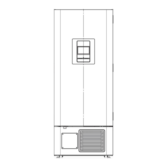
- Page 8 Dimension MDF-DU502VH...
- Page 9 MDF-DU702VH...
-
Page 10: Cooling Unit Parts
Cooling unit parts MDF-DU502VH 1Φ220-240V 50/60Hz Specification Parts description Circuit H(Left side at rear view) Circuit L(Right side at rear view) Compressor Type VNEU213U VNEU213U Compressor cord LDDG000200 LDDG000200 Rated power supply Single phase, 220-240 V, 50/60 Hz Single phase, 220-240 V, 50/60 Hz Ze-NIUSL22SA Q’ty:500 cc Ze-NIUSL22SA Q’ty:500 cc Refrigeration oil... - Page 11 MDF-DU702VH 1Φ220-240V 50/60Hz Specification Parts description Circuit H(Left side at rear view) Circuit L(Right side at rear view) Compressor Type VNEU213U VNEU213U Compressor cord LDDG000200 LDDG000200 Single phase, 220-240 V, 50/60 Hz Single phase, 220-240 V, 50/60 Hz Rated power supply Ze-NIUSL22SA Q’ty:500 cc...
- Page 12 Refrigeration circuit Binary refrigerating cuircuit 〈cascade system〉 〈MDF-DU502VH/DU702VH) High temp. Low temp. Compressor (H) Pre-Condenser Cascade Frame Pipe Dehydrator Condense Capillary Tube (H) Suction heat exchanger Cascade Condenser Compressor (L) Capillary Tube (L)
-
Page 13: Component On Pcb
Components on PCB CN11 CN12 #1,#2 #1,#3 Main Battery SW Battery SW CN101 #1,#4 Power SW CN14 Recorder #1-#6 (option) Backup Battery Remote alarm terminal #1: COM #2: N.O. #3: N.C. #1,#7:USB PCB #8,#9:Door SW #1-#6 MTR-480,MTR-L03 (option) #1-#2 AT sensor CN103 #1,#3:... -
Page 14: Connection On Pcb
Connections on PCB The following shows connections of connector on Main PCB. Connector Connects to Usage Emulator To version up firmware #1~#6: MTR-480/MTR-L03 (Option) To connect with MTR-480/MTR-L03. Remote alarm terminal #1: COM Remote alarm contact outputs. #2: N.O. #3: N.C. #1~#2 Jumper To upgrade firmware version To connect with LCD PCB... -
Page 15: Electric Part
Electric parts MDF-DU502VH ーPA ーPE MDF-DU702VH Compressor(A)(B) Type VNEU213U VNEU213U Rating 220-240 V, 50/60 Hz 220-240 V, 50/60 Hz Inverter Type VCCHP2456 VCCHP2456 Rating 220-240 V, 50/60 Hz 220-240 V, 50/60 Hz Condensing fan motor Type SV4-11AB5P SV4-11AB5P Rating 230 V,10 W 230 V,10 W Capi. -
Page 16: Specifications Of Sensor
Specifications of sensor The following shows the temperature in thermal sensor (502AT-11) and its resistance value. Temp. Resistance Temp. Resistance Temp. Resistance (℃) Value (kΩ) (℃) Value (kΩ) (℃) Value (kΩ) -50 -7 154.6 17.93 8.167 -45 -6 116.5 17.16 7.853 -40 -5... -
Page 17: Wiring Diagram -
Wiring Diagram -14-... -
Page 18: Circuit Diagram
Circuit Diagram main -15-... - Page 19 power -16-...
- Page 20 -17-...
-
Page 21: Operation
Operation How to operate Service # 1 and Service # 2 on the service menu is described below. For other operations on the LCD, refer to the instruction manual. Term Function Runtime Display the accumulate time of Main battery, Backup battery FAN A and FAN B, Reset them. - Page 22 (Runtime,Version Up) Move to Service Code input display, so Keep touching MENU KEY (5 sec) input “384” or “335232” Move Service Input “384”, Move to Menu display, touch service #1 display, touch Runtime only can check key. or Version Up key the firmware version.
- Page 23 (Temperature calibration procedure:chamber sensor) Move to Service Code input display, Keep touching MENU KEY (5 sec) so input “335232” Move to Service display, touch Temp. Move to Menu display, touch Service #2 Calibration key key. -43.3 Touch mark area. Move to input value display. Input measured value by thermometer -43.3 -43.3...
- Page 24 (Operation System Configuration #1) Move to Service display, touch System Move to Menu display, touch Service #2 key. Configuration #1 key Capi. Heater Timer Slide key ON(enable), ■ setting time(Default 8 min). Capi. Heater Start Capi. heater control setting (0) Heater on once in 18 hours (1) Force on now (2) Force off now(default)
- Page 25 (Operation Configuration #2,Status) Move to System Configuration #2 AIP Heater ON/OFF AIP Heater set Backup Function Backup function set. Refer to backup cooling kit Overload Alarm Delay Set Overload Alarm Delay (1)6 hour (2)2 day (3)5 day(Default) Note: Use for validation Move to Status display Move to next page.
- Page 26 Function Code 925:Flash memory Initialization Model Code Set model (1) MDF-DU502VH (2) MDF-DU702VH Use for the version up of the firmware ・Check if USB memory is connected ・If not connected, "USB memory is disconnected." is displayed ・Communicate with ErrorLog command read request (0xA0) ·...
- Page 27 (Operation Setup Data , Other Setting) Move to Setup Data display USB memory data can be import and export Move to Version Up display Import data: setting data Export data: daily information Data Export ・Confirm the connection of USB memory “...
- Page 28 Control specification 1.Temperature control Outline This unit controls two comp.s on the H side and the L side in cooperation, and controls the temp. inside the refrigerator to the set temp. (two-way freezing). Furthermore, since the two comp.s are of inverter type and the number of revolutions can be changed, PID control is used in the vicinity of the set temp.
- Page 29 2.Compressor normal mode (Speed control) Three type of comp. operation mode depending the chamber temp. ≦set temp.(SV) > set temp.(SV) < set temp.(SV) Chamber temperature + Proportional band lower - Proportional band + Proportional band limit (EL) upper limit (EH) lower limit (EL)≧...
- Page 30 First at 2500 rpm, Return to 3000 rpm with cascade temperature below -20 ° C ⑥ Transition conditions from the initial startup period to the constant-speed initial period (OR) ・Initial startup period has passed 120 sec or more ・Other than the conditions below Extended for 30 sec when the cascade temp.
- Page 31 4.Capi. heater control (1)Outline In order to prevent oil clogging in the capillary, the compressor is periodically stopped, and the heater attached to the capillary is energized. Even if the compressor is in operation, the compressor is forcibly stopped for a certain period depending on the condition.
- Page 32 7.Alarm type Table Alarm type Code Name Class Judgment condition Temp. alarm High temp. alarm the chamber temp. exceeds the warning temp. Temp. alarm Low temp. alarm The cahmber temp. falls below the warning temp. Power failure Power failure alarm During detecting power failure alarm -...
- Page 33 8.Alarm function Alarm delay ・ Even if the judgment is alarm, buzzer sound and remote alarm is not output within the set time. (after passing set time, the status become alarm.) ・ Set range of alarm delay time:※ restrict input by touch panel side. Temp.
- Page 34 10.Model Model code 1: MDF-DU502VH 2: MDF-DU702VH Parameter Default Module Term MDF-DU502VH MDF-DU702VH Range -50℃ ~ -90℃ Comp. control Set temp. -80℃ -80℃ Control mode Auto Auto Comp. first start delay 3 min 3 min 3 min~15 min time Comp. restart delay time...
- Page 35 Default Module Item MDF-DU502VH MDF-DU702VH Range High temp. alarm +5℃ ~ +40℃ Alarm +10℃ +10℃ temp. -5℃ ~ -40℃ Low temp. alarm -10℃ -10℃ temp. Temp. alarm delay 15 min 15 min 0 min~15 min time Door alarm delay 2 min 2 min 0 min ~15min...
- Page 36 Inverter signal Outline In this model, an inverter is used for compressor control. In order to investigate the status of the compressor and the inverter, signal verification of the inverter side is necessary. The error signal on the inverter side is as follows. Failure Mode LED operation Normal operation...
-
Page 37: Parts Layout
Parts layout 【Front/Control panel】 【Opposite side of control panel】 【Opposite side of front door /auto air intake port】 LCD panel LCD PCB 【Left side】 Door latch support Inner door latch support Inner door latch Handle Air intake port 【Chamber】 【Lower Right side】 PT sensor Battery switch Power switch... - Page 38 【Lower right side/Electric Box】 Main PCB メイン基板 【Lower front/Condenser】 【Rear bottom/Cooling UNIT】 Inverter H Inverter L Compressor L Compressor H -35-...
- Page 39 Repairing unit / Gas charge ■Preparations(H/L side common) · Refrigerant cylinder (type, amount required to be confirmed), refrigerant cylinder hose · Alarm · Detector (gas leak tester for HC refrigerant) · Dedicated gauge manifold (dedicated GM) (combined with R290 · R170) ·...
- Page 40 ■Caution ・Use of fire is strictly prohibited during HC gas release and its charge. Especially, pay shut attention for product around and the release port. ・Confirm in advance about the power supply of the work place, weld work availability, carry-in / out route.
- Page 41 ■Common work for high temperature side and low temperature side 1. Release gas 1.1Securing work space Preparations :Alarm (Note: Alarm should be operated at all times during work) Procedure: Move to the space where you can work the product, open the window / door and set the alarm on the floor within 50 cm radius from the unit.
- Page 42 Low temperature L side Valve state High temperature L side Pipe position of MDF-DU702VH Note:Piercing tool is unnecessary if service valve is attached. Place the detector near the tip of the outdoor long hose. Be sure to use a detector that can detect HC refrigerant.
- Page 43 1.4 Vacuum evacuation of cooling circuits preparation :Explosion-proof vacuum pump, detector for HC refrigerant procedure:Since the refrigerant is dissolved in the compressor oil, connect the explosion-proof vacuum pump to the tip of the long hose led outdoors, and perform vacuum evacuation from the refrigeration circuit for at least 10 minutes.
- Page 44 1.6 Nitrogen charge before nitrogen blowdown procedure :After 1.5 , VC, VG are shut, VR, VH, VL are opened and nitrogen is charged (about 30 seconds) (however, the secondary pressure is 0.5-0.7 MPa) note:In order to prevent air from entering the freezing circuit, fill with nitrogen. Valve state open shut...
- Page 45 Remove the label of the pipe to be welded. Service valve MDF-DU702VH NOTE :Check valve is also called "access connector". When the check valve is welded, it will be hot, so remove the valve before doing. If the check valve cannot be installed on the high pressure side, in the process of "13.
- Page 46 2.2 Preparation for gas welding Preparation:Flameproof sheet, tools, nitrogen cylinder, charge hose, branching instrument Procedure : Pull the welded part as far as possible from the product and cover the periphery with a flameproof sheet as necessary. In order to prevent oxide film of pipe inside during welding, a nitrogen cylinder is connected to the low pressure side service valve (SVL) Replace the nitrogen in the piping.
- Page 47 3.Evacuation 3.1 Leak check of connection point Preparation: Leak check spray (liquid detergent may be used), dedicated GM, general purpose GM *, powerful vacuum pump, Nitrogen cylinder, charge hose, branching equipment, tools * In case of evacuating simultaneously on the low temperature side and the high temperature side Procedure: Connect as shown below and prepare for vacuum evacuation.
- Page 48 3.2 Evacuation① Procedure:Remove the hose of the general purpose GM (or coolant Valve state port) that was connected from the nitrogen cylinder, open the open shut nitrogen, shut the valve (or VR) of the removed hose, and ○ perform vacuum evacuation to fill the refrigerant. After ○...
- Page 49 4.Gas charge 4.1 Evacuation② Preparations: Dedicated GM, Refrigerant Cylinder, Bottle Cap, Powerful Vacuum Pump, Scale (Electronic Weighing Scale), Charge hose, branching tool, tool Procedure : After operating the powerful vacuum pump with the refrigerant cylinder on the scale, Open the valve in the following order and evacuate to the refrigerant cylinder. VS⇒VR⇒VG⇒VC.
- Page 50 4.3 Preparation for charge Preparation: Leak check spray Procedure: Re-check the type of refrigerant and the amount sealed. Open the valve slowly in the order of the main valve of the refrigerant cylinder → VS → VR → VL, the indication of scale. After stabilizing (calm down), reset the display of scale.
- Page 51 4.5 Stop gas charge Preparations :Tools, Explosion-proof vacuum pump Procedure : As shown in the figure below, let the long hose outdoors and connect the explosion-proof vacuum pump. Activate the pump, open the valves (VC, VG, VL, VR, VS) and suck out the remaining refrigerant of the hose / general purpose When release of the refrigerant is completed, shut all the valves and stop the pump.
- Page 52 ■L(low temperature)cooling circuit The work content on the low temperature side is work on the high temperature side 3.3 After completing vacuum evacuation, work to enclose pentane is added. After that, work from the work of vacuum evacuation ② in the same procedure as the high temperature side. Describe additional pentane inclusion work below.
- Page 53 Procedure2: Dip the tip of the pentane dryer in pentane solution. With the VCU opened slightly, opening the VCL slowly will cause the pentane to begin to be sucked into the cylinder. When the specified amount of pentane is sucked into the cylinder, pull out of pentane ends when VCL is "shut".
- Page 54 Procedure 2: Shut the valves VC and VG, then open the valve VL. Valve Operation Holding the pentane cylinder vertically, slowly open the open shut VCL and aspirate the pentane into the circuit. ○ At this time, pull in while watching the guide of the ○...
- Page 55 Test Data MDF-DU502VH(1φ230V 50Hz) AT30℃ Pull-down & Pull-up Temperture AT35℃ Pull-down Pressure Pull-down H Pd H Ps Pull-up L Pd L Ps -100 10 11 12 13 14 15 10 11 12 13 14 15 Time [hour] Time [hour] AT35℃ Pull-down Temperture AT35℃...
- Page 56 MDF-DU502VH(1φ220V 60Hz) AT30℃ Pull-down & Pull-up Temperture AT35℃ Pull-down Pressure H Pd H Ps Pull-down L Pd L Ps Pull-up -100 10 11 12 13 14 15 10 11 12 13 14 15 Time [hour] Time [hour] AT35℃ Pull-down Temperture AT35℃ Pull-down Current-Input Current 1/2H...
- Page 57 MDF-DU702VH(1φ230V 50Hz) AT35℃ Pull-down Pressure AT30℃ Pull-down & Pull-up Temperture H Pd H Ps Pull-down L Pd L Pd Pull-up -100 10 11 12 13 14 10 11 12 13 14 15 Time [hour] Time [hour] AT35℃ Pull-down Temperture AT35℃ Pull-down Current-Input...
- Page 58 MDF-DU702VH(1φ220V 60Hz) AT30℃ Pull-down & Pull-up Temperture AT35℃ Pull-down Pressure Pull-down H Pd H Ps Pull-up L Pd L Ps -100 10 11 12 13 14 10 11 12 13 14 15 Time [hour] Time [hour] AT35℃ Pull-down Current-Input AT35℃ Pull-down Temperture...
- Page 59 Temperature uniformity - 17points measuring MDF-DU502VH Back Top of interior Upper area measuring points ② ④ ①~④: ⑤ 140mm(H) from the top of interior 60mm(D) and 63mm(W) from each corners of the interior. 140mm(H Front ① ③ ⑤: 140mm(H) from the top of interior ⑯...
- Page 60 Internal Temperature Uniformity (Reference Data) MDF-DU502VH <Conditions> Ambient temperature: 23/30℃ Load: Unloaded <Distribution data> <Distribution data> Temperature of the cycle in each area (SV=-80℃、air temperature) Temperature of the cycle in each area (SV=-70℃、air temperature) Unit:℃ Unit:℃ Ambient temperature 23℃ Ambient temperature 23℃ 230V,50Hz 220V,60Hz 230V,50Hz...
- Page 61 Running Cycle MDF-DU502VH Condition : SV=-80℃ AT30℃ 230V,50Hz Condition : SV=-80℃ AT23℃ 230V,50Hz ⑤ ⑩ ⑮ ⑯ ⑰ ⑤ ⑩ ⑮ ⑯ ⑰ Time [hour] Time [hour] Condition : SV=-70℃ AT30℃ 230V,50Hz Condition : SV=-70℃ AT23℃ 230V,50Hz ⑤ ⑩ ⑮ ⑯...
- Page 62 MDF-DU502VH Condition : SV=-80℃ AT23℃ 220V,60Hz Condition : SV=-80℃ AT30℃ 220V,60Hz ⑤ ⑩ ⑮ ⑯ ⑰ ⑤ ⑩ ⑮ ⑯ ⑰ Time [hour] Time [hour] Condition : SV=-70℃ AT23℃ 220V,60Hz Condition : SV=-70℃ AT30℃ 220V,60Hz ⑤ ⑩ ⑮ ⑯ ⑰ ⑤...
- Page 63 Temperature uniformity - 17points measuring MDF-DU702VH Back Top of interior Upper area measuring points ② ④ ①~④: ⑤ 140mm(H) from the top of interior 60mm(D) and 87mm(W) from each corners of the interior. 140mm(H Front ① ③ ⑤: 140mm(H) from the top of interior ⑯...
- Page 64 Internal Temperature Uniformity (Reference Data) MDF-DU702VH <Conditions> Ambient temperature: 23/30℃ Load: Unloaded <Distribution data> <Distribution data> Temperature of the cycle in each area (SV=-80℃、air temperature) Temperature of the cycle in each area (SV=-70℃、air temperature) Unit:℃ Unit:℃ Ambient temperature 23℃ Ambient temperature 23℃...
- Page 65 Running cycle MDF-DU702VH Condition: SV-80℃, AT23℃ 230V 50Hz Condition: SV-80℃, AT30℃ 230V 50Hz ⑤ ⑩ ⑮ ⑯ ⑰ ⑤ ⑩ ⑮ ⑯ ⑰ Time[hour] Time[hour] Condition: SV-70℃, AT30℃ 230V 50Hz Condition: SV-70℃, AT23℃ 230V 50Hz ⑤ ⑩ ⑮ ⑯ ⑰...
- Page 66 MDF-DU702VH Condition: SV-80℃, AT23℃ 220V 60Hz Condition: SV-80℃, AT30℃ 220V 60Hz ⑤ ⑩ ⑮ ⑯ ⑰ ⑤ ⑩ ⑮ ⑯ ⑰ Time[hour] Time[hour] Condition: SV-70℃, AT23℃ 220V 60Hz Condition: SV-70℃, AT30℃ 220V 60Hz ⑤ ⑩ ⑮ ⑯ ⑰ ⑤ ⑩...
- Page 67 Backup cooling kit installation and setting procedure Confirmation of packing items ① Before installing the optional component, check the accessories listed in table 1 below are enclosed. Table 1 PARTS NAME APPEARANCE THE EXPLANATION OF THE USE Q'TY. Electromagnetic valve for injecting the LCO CO2 solenoid valve gas into the freezer chamber (put together Assy.
- Page 68 Solenoid valve cover attachment For fixing the solenoid valve cover. 11 Binder For fixing the thermal insulation. For fixing the back-up cooling kit body(4). Truss screw For fixing the battery(4). M4×10 For fixing the nozzle cover(2). stainless For fixing the solenoid valve cover(2). For fixing the CO solenoid valve assy(4).
- Page 69 BACKUP COOLING KIT INSTALLATION ② Unravel the bundled harness Harness UB_BATTRY_1 R,BL 3P-3P Harness MAIN_UBK BL,R,OR.BU.Y.W 6P-6P,3P Harness UB_VALVE_1 Y,G 2P-2P Fig.2-1 ③ Remove the product unit cover R and the switch box cover switch box cover unit cover-R installation position for backup cooling kit body installation position for battery Fig.3-1 Fig.3-2...
- Page 70 ⑥ Wire the gas sensor cable using the clampers on the marking section on the bellow. CAP A Remove CAP A attached to the base and wire the cable of the gas sensor from the hole of the base to the back of the body. ...
- Page 71 ⑩ Remove the sensor outlet cover on the back and the temperature insert hole for the censor control sensor cover inside the chamber, and remove the silicone censor cover of back-up kit in the backup sensor insertion hole. Insert the gas thermo into the backup sensor insertion hole from which silicon has been removed and fix the gas thermo using the nylon clip attached to the sensor mounting plate.
- Page 72 ⑬ Insert the valve pipe from the back and secure it with the connect to harness mounting plate. Bend the valve tip downward at 90 degree. After inserting the gas pipe, fill the gap with silicon. When the cover is attached, the tip of the valve pipe does not interfere with the cover.
- Page 73 WIRING -70-...
- Page 74 PRECAUTIONS Before installation ●Liquid CO cylinder should be a siphon type cylinder ●Only liquid CO can be used for this system. Never use other kinds of gases. ●Liquid CO loses its cooling capacity when the ambient temperature is above +31℃. Do not install the liquid CO cylinder in a place exposed to direct sunlight or near heat-emitting appliances such as stoves and heaters.
- Page 75 INSTALLATION 1. Put the liquid CO cylinder into the CO cylinder stand. Secure each cylinder to the stand with chains. 2. Connect the valve on the CO cylinder stand with the CO outlet of the cylinder with a flexible hose. 3.
- Page 76 SETTING ①Press Menu key at lower right of TOP display for 5 second ②Move to Service Code display. Input “335232” with number key at right of the display. And press OK ③Move to Menu display, press Service #2 key at the lower middle of the display.
- Page 77 ⑥Move to Service display, press TOP key at upper right of the display. ⑦Move to TOP display, make sure that display at Backup. Now this operation is completed. MDF-DU500VX AT23℃ no load SV=70℃ sensor sensor -74-...
- Page 78 *Revision history Revision # Date of revision Reason of revision SM0000002-01 Oct.17. 2017 Update Service manual for released catalogue. Change firmware version to V1.04A for main PCB to fix the malfunction for SM0000002-02 Oct.27. 2017 optional backup system, MDF-UB7. SM0000002-03 Feb.7.