
Related Manuals for Panasonic MDF-U5312


Summary of Contents for Panasonic MDF-U5312
-
Page 1: Operating Instructions
Operating Instructions Biomedical Freezer MDF-U5312 MDF-U5312 Series Please read these instructions carefully before using this product, and save this operating instructions for future use. See page 33 for all Model numbers. -
Page 2: Table Of Contents
CONTENTS INTRODUCTION P. 2 PRECAUTIONS FOR SAFE OPERATION P. 3 ENVIRONMENTAL CONDITIONS P. 7 FREEZER COMPONENTS P. 8 Control panel P. 10 INSTALLATION SITE P. 11 INSTALLATION P. 12 START-UP OF UNIT P. 13 TEMPERATURE SETTING P. 14 Key lock function P. -
Page 3: Introduction
INTRODUCTION Read this operating instructions carefully before using the appliance and follow the instructions for safety operation. Our company never guarantee any safety if the appliance is used for any objects other than intended use or used by any procedures other than those mentioned in this operating instructions. Keep this operating instructions in an adequate place to refer to it as necessary. -
Page 4: Precautions For Safe Operation
PRECAUTIONS FOR SAFE OPERATION It is imperative that the user complies with this operating instructions as it contains important safety advice. Items and procedures are described so that you can use this unit correctly and safely. If the precautions advised are followed, this will prevent possible injury to the user and any other person. - Page 5 PRECAUTIONS FOR SAFE OPERATION WARNING Do not use the unit outdoors. Current leakage or electric shock may result if the unit is exposed to rain water. Only qualified engineers or service personnel should install the unit. The installation by unqualified personnel may cause electric shock or fire. Install the unit on a sturdy floor and take an adequate precaution to prevent the unit from turning over.
- Page 6 PRECAUTIONS FOR SAFE OPERATION WARNING Ensure you do not inhale or consume medication or aerosols from around the unit at the time of maintenance. These may be harmful to your health. Never splash water directly onto the unit as this may cause electric shock or short circuit. Never put containers with liquid on the unit as this may cause electric shock or short circuit when the liquid is spilled.
- Page 7 PRECAUTIONS FOR SAFE OPERATION CAUTION Use a dedicated power source (a dedicated circuit with a breaker) as indicated on the rating label attached to the unit. A branched circuit may cause fire resulting from abnormal heating. Connect the power supply plug to the power source firmly after removing the dust on the plug. A dusty plug or improper insertion may cause a heat or ignition.
-
Page 8: Environmental Conditions
ENVIRONMENTAL CONDITIONS This equipment is designed to be safe at least under the following conditions (based on the IEC 61010-1): Indoor use; Altitude up to 2000 m; Ambient temperature 5 C to 40 Maximum relative humidity 80% for temperature up to 31 C decreasing linearly to 50% relative humidity at 40 Mains supply voltage fluctuations up to ±10% of the nominal voltage;... -
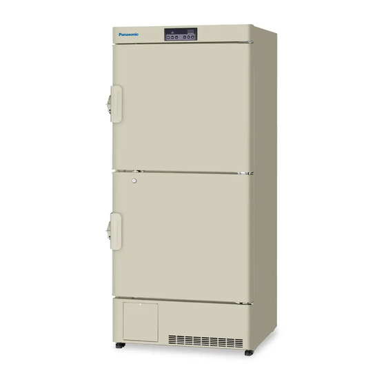
Page 9: Freezer Components
FREEZER COMPONENTS Back side... - Page 10 FREEZER COMPONENTS 1. Outer door: To open the door, grip the handle. On closing, lock the door latch completely. 2. Handle: Always grip the handle to open the outer door. 3. Lock: Turn clockwise to 180 with a key and the outer door is securely locked. 4.
-
Page 11: Control Panel
FREEZER COMPONENTS Control panel 1. Alarm lamp (ALARM): This lamp is flashed when the audible alarm is activated. 2. Digital temperature indicator: This indicator shows the present chamber temperature or set temperature. 3. Numerical value shift key ( ): Pressing this key in the setting mode causes the numerical value to shift. -
Page 12: Installation Site
INSTALLATION SITE To operate this unit properly and to obtain maximum performance, install the unit in a location with the following conditions: A location not subjected to direct sunlight Do not install the unit under direct sunlight. Installation in a location subjected to direct sunlight cannot obtain the intended performance. -
Page 13: Installation
INSTALLATION 1. Removing the packaging materials and tapes Remove all transportation packaging materials and tapes. Open the doors and ventilate the unit. If the outside panels are dirty, clean them with a diluted neutral dishwashing detergent. (Undiluted detergent can damage the plastic components. For the dilution, refer to the instruction of the detergent.) After the cleaning with the diluted detergent, always wipe it off with a wet cloth. -
Page 14: Start-Up Of Unit
START-UP OF UNIT Follow the procedures for the initial and consequent operations of the unit. 1. Connect the power cord to the dedicated outlet having appropriate rating with the chamber empty, and turn on the power switch on the freezer. 2. -
Page 15: Temperature Setting
TEMPERATURE SETTING Table 1 shows the basic procedure for setting the chamber temperature. Perform key operations in the sequence indicated in the table. The example in the table is based on the assumption that the desired temperature is -25 Note: The unit is set at the factory that the chamber temperature is -30 Table 1. -
Page 16: Alarm Temperature Setting
ALARM TEMPERATURE SETTING This unit is provided with both high and low temperature alarms. The temperature at which the alarm is activated can be changed. The available set range for high temperature alarm is between +5 C and +15 C, and -5 C and -15 C for low temperature alarm against the set temperature. -
Page 17: Setting Of Alarm Resume Time
without any key operation. In this case, any setting before pressing set key (SET) is not memorized. SETTING OF ALARM RESUME TIME The buzzer and remote alarm are stopped by pressing buzzer stop key (BUZZER) on the control panel during alarm condition. The buzzer and remote alarm will be activated again after certain suspension if the alarm condition is continued. -
Page 18: Remote Alarm Terminal
REMOTE ALARM TERMINAL WARNING Always disconnect the power supply cord before connecting an alarm device to the remote alarm terminal. The remote alarm terminal is installed at the back of the unit. The alarm is outputted from this terminal. Contact capacity is DC 30 V, 2 A. Contact output: between COM. -
Page 19: Alarms & Safety Functions
ALARMS & SAFETY FUNCTIONS This unit has the alarms and safety functions shown in Table 6, and also self diagnostic functions. Table 6 Alarms and safety functions Alarm Situation Indication Buzzer Safety functions If the chamber temperature is higher Alarm lamp is flashed. High temperature Intermittent tone with Remote alarm with 15... -
Page 20: Routine Maintenance
ROUTINE MAINTENANCE WARNING Always disconnect the power supply to the unit prior to any repair or maintenance of the unit in order to prevent electric shock or injury. Ensure you do not inhale or consume medication or aerosols from around the unit at the time of maintenance. -
Page 21: Troubleshooting
TROUBLE SHOOTING If the unit malfunctions, check out the following before calling for service. Malfunction Check/Remedy The circuit breaker of power source is active The chamber is not cooled The voltage is too low. (In this case, call an electrician.) at all The power switch is not ON. -
Page 22: Disposal Of Unit
DISPOSAL OF UNIT WARNING If the unit is to be stored unused in an unsupervised area for an extended period ensure that children do not have access and doors cannot be closed completely. The disposal of the unit should be accomplished by appropriate personnel. Always remove doors to prevent accidents such as suffocation. - Page 23 The symbol mark and recycling systems described below apply to EU countries and do not apply to countries in other areas of the world. Your Panasonic product is designed and manufactured with high quality materials and components which can be recycled and/or reused.
- Page 24 POUR LES UTILISATEURS DE UE Le symbole et les systèmes de recyclage évoqués ci-dessous s'appliquent uniquement aux pays de UE. Votre produit Panasonic est conçu et fabriqué avec des composants et des matériaux de hautes qualités qui peuvent être recyclés et/ou réutilisés.
- Page 25 PER UTENTI UE Il simbolo e i sistemi di riciclaggio descritti di seguito si applicano esclusivamente ai paesi dell’UE. Questo prodotto Panasonic è stato progettato e realizzato con materiali e componenti di elevata qualità che possono essere riciclati e/o riutilizzati.
- Page 26 Het symbool en de recycleersystemen die hieronder beschreven worden, zijn van toepassing op de landen in de EU en zijn niet van toepassing op landen in andere delen van de wereld. Uw Panasonic product is ontworpen en gemaakt met materialen en onderdelen van hoge kwaliteit, die gerecycleerd en opnieuw gebruikt kunnen worden.
-
Page 27: Disposal Of Battery
DISPOSAL OF BATTERY This unit is provided a nickel-metal-hydride battery for the power failure warning device. The battery is located in the electrical box inside the cover on the upper side. (Fig. 2) The high voltage components are enclosed in the electrical box. The cover should be removed by a qualified engineer or a service personnel only to prevent the electric shock. -
Page 28: Temperature Recorder (Option)
TEMPERATURE RECORDER (OPTION) WARNING Always disconnect the power supply to the unit prior to attachment of a temperature recorder in order to prevent electric shock or injury. A temperature recorders is available for the freezer as the optional component. The type of the temperature recorder is MTR-G85A or MTR-G85C and MTR-4015LH. - Page 29 TEMPERATURE RECORDER (OPTION) 5. Place the recording paper between the guide and the guide plate. Slide the recording paper along the guide plate so that the recording paper will not be forced out of the date/hour slot. See Fig. 5. 6.
-
Page 30: Setting Of Mtr-G85A Or Mtr-G85C
TEMPERATURE RECORDER (OPTION) Setting of MTR-G85A or MTR-G85C If the warning is required for the internal temperature record or the interior temperature deviates from the target temperature, an optional temperature recorder is available. Install the recorder properly as described below. Chart guides Ink pen arm Back-up battery... - Page 31 TEMPERATURE RECORDER (OPTION) Starting recording and setting the time: Turn the power switch ON. The pen will move inward on the circular recording paper and stop temporarily at the 0% position (equivalent to the 40 C line). Then the ink pen will Ink pen move to the position which indicates the measured Hour...
-
Page 32: Specifications
SPECIFICATIONS Biomedical Freezer Product name MDF-U5312 External dimensions W804 mm x D772 mm x H1802 mm Internal dimensions W658 mm x D607 mm x H1272 mm Effective capacity 482 L Exterior Painted steel Interior Styrol resin Insulation Rigid polyurethane foamed-in place... -
Page 33: Performance
PERFORMANCE Biomedical Freezer Product name MDF-U5312 MDF-U5312 MDF-U5312 MDF-U5312 MDF-U5312 MDF-U5312 Model No. Cooling performance C (ambient temperature; 35 C, no load) Temperature control range C to -30 Power voltage AC 110V AC 115 V AC 220 V AC 220 V... -
Page 34: Safety Check Sheet
CAUTION Please fill in this form before servicing. Hand over this form to the service engineer to keep for his and your safety. Safety check sheet 1. Freezer contents : □Yes □No Risk of infection: □Yes □No Risk of toxicity: □Yes □No Risk from radioactive sources:... - Page 35 Printed in Japan 1-1-1 Sakata, Oizumi-Machi, Ora-Gun, Gunma 370-0596 Japan 7FB6P151607001 © Panasonic Healthcare Co., Ltd. 2012 S0412-10412...