KEB Combivert F5 Instruction Manual
Lift
Hide thumbs
Also See for Combivert F5:
- Applications manual (378 pages) ,
- Reference manual (349 pages) ,
- Instruction manual (196 pages)

Related Manuals for KEB Combivert F5


Summary of Contents for KEB Combivert F5
- Page 1 LIFT TECHNOLOGY Instruction Manual COMBIVERT F5-Lift Version 2.2 Mat.No. Rev. 00F5LEB-K220...
-
Page 3: Table Of Contents
Table of Contents 1. Introduction ........................4 Preface ............................... 4 Product description .......................... 4 Safety and Operating Instructions ....................5 2. Overview of control connections ...................6 Housing sizes D…E .......................... 6 Housing sizes G…U .......................... 6 Motor encoder connection X3A ....................... 7 2.3.1 Incremental encoder interface ...................... -
Page 4: Introduction
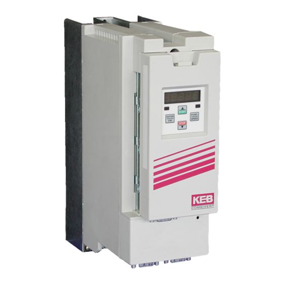
Help Product description This instruction manual describes the frequency inverter series KEB COMBIVERT F5 for lift drives. This series convinces through the special adaption of the operation to the requirements of lift drives. The lift functions are available only in connection with the lift operator (part number 00.F5.060-200C software version 2.2). -
Page 5: Safety And Operating Instructions
Important, absolutely read Safety and Operating Instructions Safety and Operating Instructions for drive converters (in conformity with the Low-Voltage Directive 2006/95/EG) 1. General portation or handling. No contact shall be made with In operation, drive converters, depending on their de- electronic components and contacts. -
Page 6: Overview Of Control Connections
Description of the Unit Overview of Control Connections Housing sizes D…E Lift operator (00.F5.060-200C) HSP5 interface RS232/485 interface Control terminal strip Lift shaft encoding Motor encoder Housing size G…U Lift operator (00.F5.060-200C) HSP5 interface RS232/485 interface Lift shaft encoding Motor encoder Control terminal strip Observe maximum width of the connectors for X3A and X3B ! -
Page 7: Motor Encoder Connection X3A
Description of the Unit Motor encoder connection X3A The connection of the motor encoder is done on socket X3A. Which of the encoders can be connected depends on the installed encoder interface and is displayed in LC.11. All encoder connectors may be connected / discon- nected only at switched off frequency inverter and switched off supply voltage. -
Page 8: Hiperface Encoder Interface
Description of the Unit 2.3.4 Hiperface encoder interface Name Description REF_COS Signal offset to COS REF_SIN Signal offset to SIN COS+ Incremental signal COS for counter and direction detection SIN+ Incremental signal SIN for counter and direction detection +7,5 V Power supply for encoder Reference potential for supply voltage Data-... -
Page 9: Htl Encoder Interface Without Differential Signals
Description of the Unit 2.3.8 HTL encoder interface without difference signals Name Description NO contact Error relay NO contact NC contact Error relay NC contact Switching Error relay switching contact contact HTL A+ HTL input track A+ (parallel X3A.7) HTL B+ HTL input track B+ (parallel X3A.2) +24 V Voltage output 20..30 V, power supply for the encoders... -
Page 10: Wiring Examples / Flow Charts
Description of the Unit 2.5 Wiring examples / flow charts 2.5.1 Connection F5-Lift for binary-coded setpoint selection (factory setting) Braking resistor LHF-filter Bridge Temperature Motor-PTC Motor encoder switch Impulse output/-input or SSI-input Control release Main contactors X2A.16 X2A.24 UPS-operation X2A.17 X2A.25 Direction of travel for- +24 V X2A.14 X2A.26... - Page 11 Description of the Unit Flow chart at factory setting Setpoint Bit 1 (X2A.11) Setpoint Bit 0 (X2A.10) Setpoint Bit 2 (X2A.12) forward (X2A.14) Start (X2A.16) HS (X2A.24…26) Brake (X2A.27…29) t1 t3 t6 t7 The bit sample for the setpoint values and the direction of travel is set. Immediately after that the inverter sets the output for the main contactors.
-
Page 12: Connection F5-Lift Input-Coded Setpoint Selection ((Lb.05=2, Lb.12=0, Lb.13=1)
Description of the Unit 2.5.2 Connection F5-Lift for input-coded setpoint selection (Lb.05=2, Lb.12=0, Lb.13=1) Braking resistor LHF-filter Bridge Temperature Motor-PTC Motor encoder switch Impulse output/-input or SSI-input Control release Main contactors X2A.16 X2A.24 Releveling X2A.17 X2A.25 Speed Direction of travel for- +24 V X2A.14 X2A.26... - Page 13 Description of the Unit Flow chart at input coding Leveling speed (X2A.10) rated speed (X2A.11) Inspection speed (X2A.12) forward (X2A.14) Start (X2A.16) HS (X2A.24…26) Brake (X2A.27…29) t1 t3 t6 t7 VN rated speed and direction of travel are set. Immediately after that the inverter sets the output for the main contactors.
-
Page 14: Connection F5-Lift For Ogive Travel With Correction Input (Lb.05=1, Lb.12=9)
Description of the Unit 2.5.3 Connection F5-Lift for ogive travel with correction input (Lb.05=1, Lb.12=9) Braking resistor LHF-filter Bridge Temperature Motor-PTC Motor encoder switch Impulse output/-input or SSI-input Control release Main contactors X2A.16 X2A.24 Correction input X2A.17 X2A.25 Direction of travel for- +24 V X2A.14 X2A.26... - Page 15 Description of the Unit Flow chart for digital direct approach, peak arch with correction Setpoint Bit0 (X2A.10) Setpoint Bit1 (X2A.11) set setpoint value LF.21 to „0“ Setpoint Bit2 X2A.12) Correction (X2A.17) Start (X2A.16) Reverse (X2A.15) Ready for operation signal (X2A.18) Brake (X2A.27…29) Main contactors (X2A.24...26) GB - 15...
-
Page 16: Connection F5-Lift For Ups-Run
Description of the Unit 2.5.4 Connection F5-Lift for UPS operation Lift control Phase monitoring F5-Lift 230V AC 1ph We recommend the use of chokes to avoid current peaks. Without chokes the UPS may be bigger or go to the limit. Alternatively a single-phase transformer 230 V AC can be used at 380 V AC. - Page 17 Description of the Unit Connection F5-Lift for UPS operation (Lb.05=1, Lb.12=5) Braking resistor LHF-filter Encoder Motor-PTC Control release Main contactor X2A.16 X2A.24 UPS-operation X2A.17 X2A.25 Direction of travel +24 V X2A.14 X2A.26 forward Brake Direction of travel X2A.15 X2A.27 control reverse Setpoint Bit0 X2A.10...
- Page 18 Description of the Unit Flow chart for UPS operation (LF.27) forward (X2A.14) Control release (X2A.16) UPS operation (X2A.17) Leveling speed (X2A.11) Brake (X2A.27/28/29) HS (X2A.24/25/26) t6 t7 The travel direction and the set speeds VU and VL must be set. After a debounce timer run out the main contactors are controlled (powerless switching) .
-
Page 19: Control Terminal Strip X2A
Description of the Unit Control terminal strip X2A 1 2 3 4 5 6 7 8 9 10 11 12 13 14 15 16 17 18 19 20 21 22 23 24 25 26 27 28 29 • Tightening torque 0,22…0,25 Nm •... -
Page 20: Lift-Operator
Lift-Operator The F5-Lift operator is integrated into the FI housing by plug-in and fits into all KEB F5 lift units. Parallel to the bus operation over the RS232/485 interface the operation via integrated display/keyboard as well as a further interface for diagnosis/parameterizing (KEB COMBIVIS) is possible. -
Page 21: The Operator Panel
Description of the Unit 2.7.3 The operator panel The function key is used to change between parameter value and parameter number. FUNC. SPEED With UP (▲) and DOWN (▼) the parameter number or, in case of changeable parameters, the value is increased/ decreased. -
Page 22: Parameter Description
Parameter Description Parameter Description Overview of parameter groups The operating menu is devided into following parameter groups : Gruppe Name Function Lift basic Basic setting Lift drive Entry of the motor data Lift encoder Adjustment of motor and shaft encoder Lift Function Lift-specific adjustments Lift Posi... - Page 23 Parameter Description Display Meaning US_ro User read-only, programming inhibited, parameter can be read-only US_on User on, programming enabled Lb.02 Customer-specific password With this parameter a customer-specific password can be defined. It becomes active at the next switch-on and must then be entered before the programming of LB.01. Input Function 11…65535...
- Page 24 Parameter Description Input-coded setpoint selection (Lb.05 = 2) Speed Terminal X2A.10 Terminal X2A.11 Terminal X2A.12 Terminal X2A.13 Terminal X2A.17 VL (LF.21) VN (LF.22) VI (LF.23) V1 (LF.24) VR (LF.20) Analog setpoint setting (Lb.05 = 3 or 4) The analog setpoint setting is done over terminals X2A.1 and X2A.2. The speed is calculated according to fol- lowing formula: value „3“...
- Page 25 Parameter Description Lb.10 In-/ Output configuration With this parameter the programming of the digital inputs (Lb.11…13) and the digital outputs (Lb.14…17) can be enabled. The programming is generally inhibited for positioning operation (Lb.01 = 2…4). Input Setting Programming Description inhibited The configuration of the in- and outputs is reset to factory set- ting.
- Page 26 Parameter Description Lb.18 Brake resistance value Value range Setting Description 0,5…300,0 Ω 30,0 Ω Input of the actually used brake resistance value. With it the inverter calculates the refed energy and outputs the result in parameter LI.23. It serves as decision support on whether the employment of a feedback unit would be worth it.
-
Page 27: Input Of Motor Data
Parameter Description Input of the motor data Display Name Setting range Default setting AG Ld.00 Parameter group drIuE Ld.01 Power rating 0,10…400,00 kW 4,0 kW Ld.02 Rated speed 0,000…4000,000 1450,000 Ld.03 Rated current 0,0…710,0 A 1,0 A Ld.04 Rated frequency 0,0…710,0 Hz 50,0 Hz Ld.05... - Page 28 Parameter Description Ld.05 Cos phi Value range Setting Description 0,5…1,0 Input of the cos phi of the motor according to motor name plate. Ld.06 Rated voltage Value range Setting Description 120…830 V 400 V Input of the motor rated voltage according to motor name plate. Ld.07 Calibration of winding resistance (only at Lb.03 = A G or A GL) Value range...
- Page 29 Parameter Description Ld.11 Maximum torque of inverter Value range Setting Description 0,0…xxxx Nm Based on the peak current of the inverter, the maximum torque that can be supplied by the inverter, is displayed. Ld.12 Maximum torque limitation Value range Setting Description 0,0…xxxx Nm 0,95 •...
- Page 30 Parameter Description Adjustment of the speed encoder Display Name Setting range Default setting LC.00 Parameter group LC.01 Selection motor encoder input 0…1 LC.02 Encoder 1 Status LC.03 Encoder alarm mode 0...15 LC.11 Display Interface 1 LC.12 Increments Encoder 1 0…65535 inc 2500 Ink LC.13 Track change and travel direction inverting Encoder 1...
-
Page 31: Adjustment Of The Motor Encoder And Shaft Encoder
During read out of the encoder the error „E.Enc1“ is output. KEB identifier undefined. Storage structure of the encoder does not correspond to the KEB definition, thus data cannot be read. By writing on it the encoder is defined. Error „E.Enc1“... - Page 32 Parameter Description Value Installed encoder interface SSI - SIN/ COS In case of an invalid encoder identifier the error „E.Hyb“ is displayed in Li.01 and the measured value is indicated negated. When changing the encoder interface the error „E.HybC“ is displayed. By writing on this parameter the change is confirmed and the default values for the new interface are loaded.
- Page 33 Parameter Description LC.18 System position detection (SPI) Value range Setting Description The function SPI (static pole identification) after control release finds the system position without rotation of the after switching on motor. LC.18 determines when the function be- after direction of rotation re- comes active.
- Page 34 Parameter Description LC.24 Operation mode output If one of the encoder channels is used as encoder output, the output increments per revolution can be adapted to the requirements of the control card. Input Setting Description 256 Incr. 1024 Incr. 2048 Incr. 4096 Incr.
- Page 35 Parameter Description LC.41 SSI Clock frequency Adjustment of the clock frequency for SSI-encoder. Input Setting Description 156,25 kHz 312,5 kHz LC.42 SSI Data format Input Setting Description Binary-coded Graycode LC.43 SSI Voltage monitoring Input Setting Description GB - 35...
-
Page 36: Lift Functions
Parameter Description Lift functions Display Name Setting range Default setting LF.00 Parameter group Funct LF.01 max. speed of system 0,000…15,000 m/s 0,000 m/s LF.02 Traction sheave diameter 0…2000 mm 600 mm LF.03 Gear reduction ratio multiplier 0,00…99,99 1,00/ 30,00 LF.04 Gear reduction ration divisor 0,00...99,99 1,00... - Page 37 Parameter Description LF.00 Display of current parameter group „Funct“ LF.01 Max. speed of system This parameter limits the speed of the system to the adjusted value. For analog setpoint setting applies 0…±10 V correspond to 0…±LF.01. Value range Setting Description 0,000…15,000 m/s 0,000 m/s LF.02...
- Page 38 Parameter Description LF.12 KI Speed controller Value range Setting Description 0…32767 auto Adjustment of the I-amplification of the speed controller reset time. LF.13 KI Speed controller Offset Value range Setting Description 0…32767 auto Serves for an improved load transfer at high-efficient gearboxes. LF.14 KP Current controller Value range...
- Page 39 Parameter Description LF.22 VN Nominal speed Value range Setting Description 0,000 m/s…LF.01 0,000 LF.23 VI Inspection speed Value range Setting Description 0,000…0,630 m/s 0,000 m/s • it cannot be accelerated from the inspection speed LF.24 V 1 intermediate speed 1 Value range Setting Description...
- Page 40 Parameter Description LF.33 Jerk at begin of deceleration Value range Setting Description 0,10…9,99 m/s³ 1,00 m/s³ LF.34 Deceleration Value range Setting Description 0,10…2,00 m/s² 0,90 m/s² LF.35 Jerk at end of deceleration Value range Setting Description 0,10…9,99 m/s³ 0,70 m/s³ LF.36 Stopping jerk Value range...
- Page 41 Parameter Description LF.43 Level overspeed Value range Setting Description 0,000…18,000 m/s auto The displayed value is 110 % of the maximum speed (LF.01). LF.44 Deceleration check level Value range Setting Description 0,000…15,000 m/s auto The displayed value is 96 % of the rated speed LF.22). LF.45 Level „running open doors“...
- Page 42 Parameter Description LF.50 Drive OH Delay time If a drive shall still be made despite a hot motor, a deceleration time between warning and triggering the excess temperature error can be adjusted with this parameter. After the adjusted time has expired the inverter switches off the modulation with error E.dOH.
- Page 43 Parameter Description LF.60 Indication levelling path Value range Setting Description 0,0…264,0 cm The time of constant drive in crawl speed (VL) is measured and displayed after each run in standardized cm. . LF.61 Deceleration point Deceleration point without optimization with optimization Levelling path optimization V With the levelling distance optimization the levelling path become shorter by the entered value.
-
Page 44: Positioning Mode
Parameter Description Positioning mode / ogive run Display Name Setting range Default setting LP.00 Display „POSI“ LP.01 Ogive function 0…2 LP.02 Minimum deceleration distance (calculated) 0,0…6553,5 cm auto LP.03 Deceleration distance (measured) -3276,7…3276,7 cm 0,0 cm LP.04 Correction distance 0,0…6553,5 cm 10,0 cm LP.00 Display of current parameter group „POSI“... - Page 45 Parameter Description Ogive run with crawl path (DOL= digital ogive with leveling speed) This operating mode is recommended • for all conventional control with levelling switches. • if control run-times lead to large tolerances. • if strong slip develops on the leading sheave. •...
- Page 46 Parameter Description Ogive run with direct approach (DODA = digital ogive with direct approach) This operating mode is recommended • if the change-over of the speed inputs takes place precisely and fast (ca. 1 ms) • if the mentioned problems at ogive run with crawl path do not exist. Otherwise it result in non-levelling. The procedure is activated by adjusting the crawl speed LF.21 to 0 m/s.
- Page 47 Parameter Description LP.02 Minimum deceleration distance (calculated) Value range Setting Description 0,0…6553,5 cm auto only display LP.03 Deceleration distance (measured) Value range Setting Description -3276,7…3276,7 cm 0,0 cm Distance from deceleration point to levelling signal. LP.04 Correction distance Value range Setting Description 0,0…6553,5 cm...
-
Page 48: Information, Indications And Measured Values
Parameter description Information, indications and measured values Display Name Unit Default setting LI.00 Display „InFo“ LI.01 Inverter status LI.03 Set speed LI.04 Actual speed LI.07 Actual car speed LI.08 Floor distance LI.09 Set torque LI.10 Actual torque display LI.11 Apparent current LI.12 Actual load LI.13... - Page 49 Parameter description LI.00 Display of current parameter group „InFo“ LI.01 Inverter status This parameter shows the current status (e.g. constant run, acceleration counter-clockwise rotation) of the inverter. You find a table of all status and error messages in the annex. LI.03 Set speed Display...
- Page 50 Parameter description LI.12 Actual load Display Description 0…200 % LI.13 Peak load Display Description 0…200 % LI.14 Actual DC link voltage Display Description 0…1000 V Display of the current DC link voltage in volt. Typical values are: V-class Normal operation Overvoltage (E.OP) Undervoltage (E.UP) 230 V...
- Page 51 Parameter description LI.18 Terminal output status Decimal Output Function value X2A.18 X2A.19 X2A.24…26 Display of the currently set external and internal digital outputs. A certain value is X2A.27…29 given out for each digital output. If several outputs are activated, the sum of the internal A decimal value is displayed.
- Page 52 Parameter description LI.26 Minimum deceleration distance V Value range Description 0,0…6553,5 cm Indicates the calculated deceleration distance for V LI.27 Minimum deceleration distance V Value range Description 0,0…6553,5 cm Indicates the calculated deceleration distance for V LI.30 Inverter type Meaning Meaning Inverter size binary-coded, e.g.
- Page 53 Parameter description LI.36 Software version Operator Value range Description 0,00…9,99 Display of the software version number of the operator. LI.37 Software date Operator Value range Description 0…65535 Display of the software date of the operator in the format „DD.MM.Y“. LI.38 Software version Interface Value range Description...
- Page 54 Parameter description LI.41 Last Error (t-1) LI.42 Last Error (t-2) LI.43 Last Error (t-3) LI.44 Last Error (t-4) LI.45 Last Error (t-5) LI.46 Last Error (t-6) LI.47 Last Error (t-7) LI.48 Last Error (t-8) Value range Description 0000…5FFFh The parameters LI.41…48 show the last eight errors that occurred. The oldest error is in LI.48.
- Page 55 Parameter description LI.51 AN1 Display after amplification Value range Description 0…±400 % The parameter shows the value of the analog signal AN1 after running through the characteristic amplification in percent. The value range is limited to ±400 %. LI.52 AN2 Display before amplification Value range Description 0…±100 % The parameter shows the value of the analog signal AN2 before the characteristic amplification in percent.
-
Page 56: Adjustment Of Analog Inputs And Outputs
Parameter description Adjustment of analog inputs and outputs Display Name Setting Range Default setting LA.00 Display „AnLog“ LA.01 AN1 setpoint selection 0…2 LA.02 AN1 interference filter 0…4 LA.03 AN1 zero point hysteresis 0…±10 V 0,2 V LA.04 AN1 amplification 0,00…±20,00 1,00 LA.05 AN1 Offset X... - Page 57 Parameter description LA.03 AN1 zero point hysteresis Value range Setting Description 0…±10 % 0,2 % Through capacitive as well as inductive coupling on the inputs lines or voltage fluctuations of the signal source, the motor connected to the inverter can drift („vibrate“).
- Page 58 Parameter description LA.06 AN1 Offset Y Value range Setting Description 0,0…±100,0 % 0,0 % This parameter shifts the input characteristic on the Y-axis. LA.07 AN1 lower limit LA.08 AN1 upper limit Value range Setting Description 0,0…±400,0 LA.07 The parameter serves for the limitation of the analog signal AN1 after the -400,0 amplifier stage.
- Page 59 Parameter description LA.13 AN2 Offset X Value range Setting Description 0,0…±100,0 % 0,0 % The parameter shifts the input characteristic on the X-axis. LA.14 AN2 Offset Y Value range Setting Description 0,0…±100,0 % 0,0 % The parameter shifts the input characteristic on the Y-axis. LA.15 AN2 lower limit LA.16...
-
Page 60: Adjustment Of Torque Precontrol
Parameter description Adjustment of pretorque function 1) Preparations • Enter motor data • Connect load weighing equipment to X2A.3 and X2A.4 • Switch on the pretorque with Lb.7 =1 • Drive the cabine to the middle of the shaft • Remain at the same position in the shaft when carrying out the measurements •... - Page 61 Parameter description Example 3: Same system data as in example 2, but the installed motor is rotated by 180°. Empty cabine LI.52 = L1 = -5 % LI.10 = -1080 Nm T1 = -108 % Full cabine LI.52 = L2 = 80 % LI.10 = +1320 Nm T2 = +132 % Gain LA.12 = (-108 %-132 %)/(-5 %-80 %) = 2,82...
-
Page 62: Start-Up
Start with the basic settings (Lb-parameter). Store the adjusted data by pressing the „Enter“-key. Start-up of an asynchronous motor without speed encoder with gearbox The following procedure is recommended for the start-up of the COMBIVERT F5 Lift with a gearbox-fitted asyn- chronous motor: Lb.03: Selection of the appropriate motor type (Lb.03= A G/ 0:ASM closed loop geared) -
Page 63: Start-Up Of An Asynchronous Motor With Speed Encoder And Gearbox
Start-up Start-up of an asynchronous motor with speed encoder and gearbox Lb.03: Selection of the appropriate motor type (Lb.03= AG/ 0: ASM closed loop geared) Lb.05: Select the mode of setpoint setting Ld.01 Ld.06: Enter the motor data according to the name plate. Ld.11: If necessary, limit the maximum torque for normal operation. -
Page 64: Start-Up Of A Synchronous Motor With Speed Encoder Without Gearbox
Start-up Start-up of a synchronous motor with speed encoder without gearbox Lb.01: Input of password Lb.03: Select the appropriate motor type (Lb.03=S GL/ 3: SSM closed loop gearless) Lb.05: Select the mode of setpoint setting Lb.10: Decide, whether you want to assign other functions to the digital in-/outputs. Lb.18: If you want to know the energy losses on the braking resistor, enter the value of the brake resistor Ld.02 Ld.10: Enter the motor data according to the name plate. -
Page 65: Error Diagnosis
Error Diagnosis Error Diagnosis At KEB COMBIVERT error messages are always represented with an "E." and the appropriate error code in the display. Error messages cause the immediate deactivation of the modulation. Restart possible only after reset or autoreset. Malfunctions are represented with an "A." and the appropriate message. Reactions to malfunctions can vary. - Page 66 Error Diagnosis Display COMBIVIS Meaning The message is output if as response to a warning signal the quick-stop STOP Quick stop function becomes active. Error Messages Error: can occur in the case of switched on brake control, if the load is below the minimum load level at start up or the absence of an E.
- Page 67 Error Diagnosis Display COMBIVIS Meaning No more overload, OL-counter has reached 0%; after the error E.OL a cooling phase must elapse. This message appears upon completion of E.nOL No error overload the cooling phase. The error can be reset now. The inverter must remain switched on during the cooling phase.
- Page 68 Error Diagnosis Display COMBIVIS Meaning Error: During the initialization the power circuit could not be recognized E.Puci Error ! Unknown power unit or was identified as invalid. Error: Power circuit identification was changed; with a valid power circuit this error can be reset by writing to SY.3. If the value displayed in SY.3 E.Puch Error ! Power unit changed is written, only the power-circuit dependent parameters are reinitialized.
- Page 69 Error Diagnosis Display COMBIVIS Meaning A level between 0 and 100 % of the load counter can be adjusted, when A. OL Warning ! Overload it is exceeded this warning is output. The response to this warning can be programmed. The warning is output when the standstill continuous current is excee- ded (see technical data and overload characteristics).
- Page 70 Error Diagnosis GB - 70...
-
Page 71: Adjustment Speed Controller Of F5 Lift With "Speed Jump
Adjustment Speed Controller of F5 Lift with "speed jump" 1. Open control release (terminal X2A.16) => frequency inverter in status „noP“ 2. Select closed loop operation => Parameter LF.10 = 2 3. Motor without load 4. Set parameters LF.30, LF.31, LF.32 to maximum values 5. - Page 72 +39 02 33535311 • fax: +39 02 33500790 net: www.keb.it • mail: kebitalia@keb.it KEB Power Transmission Technology (Shanghai) Co.,Ltd. No. 435 QianPu Road, Songjiang East Industrial Zone, KEB Japan Ltd. CHN-201611 Shanghai, P.R. China 15–16, 2–Chome, Takanawa Minato-ku fon: +86 21 37746688 • fax: +86 21 37746600 J–Tokyo 108-0074...