Table of Contents
Advertisement
Advertisement
Table of Contents

Related Manuals for E-FLITE Stearman PT-17 15e ARF


Summary of Contents for E-FLITE Stearman PT-17 15e ARF
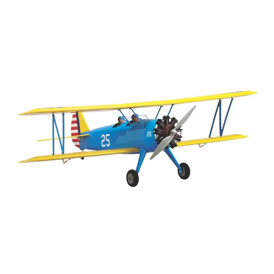
- Page 1 Stearman PT-17 15e ARF Assembly Manual Specifications Wingspan 44 in (1117mm) Length 35 in (889mm) Wing Area 608 sq in (37.5 sq dm) Weight with Battery 3.5–3.8 lb (1.5–1.7 kg) Weight without Battery 3.1–3.3 lb (1.4–1.5 kg) Pilots not included (available separately)
-
Page 2: Table Of Contents
Remember to take your time and follow the directions. for E-flite owners. Register your product today at www.E-fliteRC.com/register. E-flite Stearman PT-17 15e ARF Assembly Manual... -
Page 3: Recommended Radio Equipment
Adhesives warnings must be followed closely. Thin CA Medium CA Mishandling of Li-Po batteries can Threadlock 6-minute epoxy (HAN8000) result in fire. Always follow the manufacturer’s instructions when disposing of Lithium Polymer batteries. E-flite Stearman PT-17 15e ARF Assembly Manual... -
Page 4: Rudder And Elevator Servo Installation
Ο 5. Remove the servos. Use a 1/16-inch drill bit MatchMaker. Using sidecutters, remove three of in a pin vise to drill the mounting holes. the arms from each standard servo horn, leaving one long arm on each as shown. E-flite Stearman PT-17 15e ARF Assembly Manual... -
Page 5: Stabilizer And Fin Installation
Ο 4. Use a felt-tipped pen to mark the bottom of the Ο 2. Use a square to transfer the centerline to the stabilizer along the fuselage sides. leading edge, then make a mark 1-1/8-inches each side of the center. E-flite Stearman PT-17 15e ARF Assembly Manual... - Page 6 Ο 10. Next, insert the left and right center and outboard Ο 6. Prepare six elevator hinges by folding them in right side inboard hinge, by angling the elevator hinges in the stabilizer. half to form a crease. as shown. E-flite Stearman PT-17 15e ARF Assembly Manual...
- Page 7 Apply several drops of thin CA to each side of the joint to glue the stabilizer in place. Use a T-pin in the center of each hinge to ensure that it remains centered during installation. E-flite Stearman PT-17 15e ARF Assembly Manual...
-
Page 8: Rudder And Elevator Pushrod Installation
Use threadlock on all metal-to-metal fasteners to keep them from vibrating loose. E-flite Stearman PT-17 15e ARF Assembly Manual... - Page 9 Ο 9. Apply 1 - 2 drops of thin CA to each screw hole to for the rudder by cutting off one corner. control horn in position against the rudder and strengthen the wood and stop it from crushing. mark the screw locations with a felt-tipped pen. E-flite Stearman PT-17 15e ARF Assembly Manual...
- Page 10 2mm x 10mm machine screws using a aligned with the elevator hinge line. #0 Philips screwdriver. 1 1 0 0 E-flite Stearman PT-17 15e ARF Assembly Manual...
-
Page 11: Landing Gear Installation
3. Repeat steps 1 and 2 for the opposite side. Note: All cabane struts are the same. Use threadlock on all metal-to-metal fasteners to keep them from vibrating loose. E-flite Stearman PT-17 15e ARF Assembly Manual 1 1 1 1... - Page 12 Pin vise 1/16-inch drill bit Low-tack tape Ο 1. Prepare the aileron servos by installing the rubber grommets and bushings. ΟΟ 3. Remove the aileron hatch from the wing. 1 1 2 2 E-flite Stearman PT-17 15e ARF Assembly Manual...
- Page 13 ΟΟ 9. Apply 2-3 drops of thin CA to each hole to ΟΟ 5. Use a pencil to mark the location of the servo mark the servo mounting holes. strengthen the wood. mounting tabs. 1 1 3 3 E-flite Stearman PT-17 15e ARF Assembly Manual...
- Page 14 ΟΟ 13. Use the string to pull the aileron servo lead 2mm x 10mm sheet metal screws. enlarge the outer hole in the servo arm. through the wing. Ο 16. Repeat steps 3 through 15 for the opposite wing. 1 1 4 4 E-flite Stearman PT-17 15e ARF Assembly Manual...
-
Page 15: Aileron Installation
ΟΟ 3. Slide the aileron hinges into the hinge slots in or right as necessary to maintain an even gap the trailing edge of the lower wing panel. at each end of the aileron. 1 1 5 5 E-flite Stearman PT-17 15e ARF Assembly Manual... -
Page 16: Aileron Linkage Installation
Ο 7. Repeat steps 1 through 6 for the opposite lower ΟΟ 3. Attach a control horn to the clevis and mark the wing panel. mounting hole locations with a felt-tipped pen. 1 1 6 6 E-flite Stearman PT-17 15e ARF Assembly Manual... -
Page 17: Motor And Esc Installation
Use a low-tack tape ‘flag’ on the drill bit to prevent drilling all the way through the aileron. For the PT-17 a depth of 3/8-inch works well. Ο 7. Repeat steps 1 to 6 for the oppposite wing panel. 1 1 7 7 E-flite Stearman PT-17 15e ARF Assembly Manual... -
Page 18: Cowling Installation
4-40 x 1 inch Allen bolts and #4 washers. Use threadlock on the bolts to prevent them loosening due to vibration. The motor wires should exit towards the bottom of the fuselage. 1 1 8 8 E-flite Stearman PT-17 15e ARF Assembly Manual... -
Page 19: Interplane And Wing Transport Jig Installation
Use the cowl opening as an alignment guide by centering it on the motor. 1 1 9 9 E-flite Stearman PT-17 15e ARF Assembly Manual... - Page 20 3/8-inches (365mm) long. The lower is 10- 5/8- inches (70mm). Ο 9. Use a #0 Philips screwdriver to attach the cowling to the fuselage with four 2mm x 10mm sheet metal screws. 2 2 0 0 E-flite Stearman PT-17 15e ARF Assembly Manual...
- Page 21 Ο 6. A set of wing transport jigs is provided so that the left and right wing assemblies can be transported and installed as complete units. Use threadlock on all metal-to-metal fasteners to keep them from vibrating loose. 2 2 1 1 E-flite Stearman PT-17 15e ARF Assembly Manual...
-
Page 22: Battery Installation
Ο 2. Attach a piece of adhesive backed hook and loop tape to the battery and tray to help locate the battery and stop it moving in flight. 2 2 2 2 E-flite Stearman PT-17 15e ARF Assembly Manual... -
Page 23: Receiver Installation
Ο 5. Secure the long antenna to the front of the radio ΟΟ 3. Repeat for the opposite side and connect the tray with clear tape. leads to the receiver. 2 2 3 3 E-flite Stearman PT-17 15e ARF Assembly Manual... -
Page 24: Wing Installation
#4 washer per wing panel. Ο 3. Connect the aileron servo lead to the extension lead coming out of the fuselage. Ο 6. Remove the rubber bands and transport jigs before flight. 2 2 4 4 E-flite Stearman PT-17 15e ARF Assembly Manual... -
Page 25: Center Of Gravity
Ο 2. Install the propeller adapter and propeller. The shaft of a screwdriver or Allen wrench can be used to tighten the propeller nut. 2 2 5 5 E-flite Stearman PT-17 15e ARF Assembly Manual... -
Page 26: Control Throws
Failure of any of these components in not listed and should be adjusted according flight could mean the loss of your aircraft. to each individual model and preference. 2 2 6 6 E-flite Stearman PT-17 15e ARF Assembly Manual... -
Page 27: Safety, Precautions And Warnings
• Moisture causes damage to electronics. Avoid water you observe any erratic or abnormal operation, of power with the E-flite Power 15 so you will only need exposure to all equipment not specifically designed land immediately and do not resume flight until the to use full throttle for maneuvering. -
Page 28: Warranty Information
Horizon. Return of any goods by Purchaser must be approved in writing by Horizon before shipment. 2 2 8 8 E-flite Stearman PT-17 15e ARF Assembly Manual... - Page 29 United Kingdom available on electronics and model engines. Please call +44 (0) 1279 641 097 or e-mail us at sales@horizonhobby.co.uk with any questions or concerns regarding this product or warranty. 2 2 9 9 E-flite Stearman PT-17 15e ARF Assembly Manual...
-
Page 30: 2009 Official Academy Of Model
8. Under no circumstances may a pilot or other person touch a model aircraft in flight while it is still under power, except to divert it from striking an individual. 3 3 0 0 E-flite Stearman PT-17 15e ARF Assembly Manual... -
Page 31: Instructions For Disposal Of Weee By Users In The European Union
- Carefully plan your flight path prior to launch. - Abide by any and all established AMA National Model Aircraft Safety Code. 3 3 1 1 E-flite Stearman PT-17 15e ARF Assembly Manual... - Page 32 © 2009 Horizon Hobby, Inc. 4105 Fieldstone Road Champaign, Illinois 61822 (877) 504-0233 horizonhobby.com E-fliteRC.com Printed 06/09 15665...