Table of Contents
Advertisement
Quick Links
Horizon Hobby Deutschland GmbH
The Spektrum trademark is used with permission of Bachmann Industries, Inc.
DSM and DSM2
™
are trademarks or registered trademarks of Horizon Hobby, Inc. The Spektrum trademark is
used with permission of Bachmann Industries, Inc. Spektrum radios and accessories are exclusively available from
13351
®
© 2008 Horizon Hobby, Inc.
4105 Fieldstone Road
Champaign, Illinois 61822
(877) 504-0233
Horizon Hobby UK
Units 1-4 Ployters Rd
Staple Tye
Harlow, Essex
CM18 7NS
United Kingdom
Otto Hahn Str. 9a
25337 Elmshorn
Germany
Horizon Hobby, Inc.
www.E-fliteRC.com
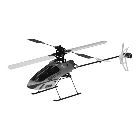
Specifications
Length . . . . . . . . . . . . . . . . . . . . . . . 20 .7 in (526mm)
Height . . . . . . . . . . . . . . . . . . . . . . . 7 .1 in (180mm)
Main Rotor Diameter . . . . . . . . . . . . . 20 .3 in (515mm)
Tail Rotor Diameter . . . . . . . . . . . . . . 3 .2 in (80mm)
Weight RTF with Battery . . . . . . . . . . . 11 .5 oz (325 g)
Main Motor . . . . . . . . . . . . . . . . . . . . High Power 370 (installed)
Tail Motor . . . . . . . . . . . . . . . . . . . . . Direct Drive N60 (installed)
Battery . . . . . . . . . . . . . . . . . . . . . . . 3S 11 .1V 800mAh LiPo (included)
Charger . . . . . . . . . . . . . . . . . . . . . . 3S 11 .1V LiPo DC Balancing (included)
Transmitter . . . . . . . . . . . . . . . . . . . . HP6DSM 2 .4GHz DSM 6-Channel (included)
Receiver . . . . . . . . . . . . . . . . . . . . . . Spektrum
AR6100 2 .4GHz DSM Microlite (installed)
™
On-Board Electronics . . . . . . . . . . . . . 2-in-1 Mixer/ESCs (installed)
Servos . . . . . . . . . . . . . . . . . . . . . . . DS75 Digital Sub-Micro (3 installed)
Gyro . . . . . . . . . . . . . . . . . . . . . . . . . G110 Micro Heading Lock (installed)
®
Advertisement
Table of Contents

Related Manuals for E-FLITE Blade CP Pro 2


Summary of Contents for E-FLITE Blade CP Pro 2
- Page 1 ® © 2008 Horizon Hobby, Inc. 4105 Fieldstone Road ® Champaign, Illinois 61822 (877) 504-0233 Horizon Hobby UK Specifications Units 1-4 Ployters Rd Staple Tye Harlow, Essex Length . . . . . . . . . . . . . . . . . . . . . . . 20 .7 in (526mm) CM18 7NS Height .
-
Page 2: Table Of Contents
Preparing for the First Flight Checklist ......................5 CP class helicopter—right out of the box, no additional parts or upgrades required . The Blade CP Pro 2 is the Flying Checklist . -
Page 3: Additional Safety Precautions And Warnings
Additional Equipment Caution: Changes or modifications not expressly approved by the party responsible for compliance could void the No additional equipment is required to complete your Blade CP Pro 2 . user’s authority to operate the equipment . This product contains a radio transmitter with wireless technology which has been tested and found to be Preparing for the First Flight Checklist compliant with the applicable regulations governing a radio transmitter in the 2 .400 GHz to 2 .4835 GHz frequency... -
Page 4: Battery Warnings, Guidelines And Charging
LiPo cells should not be discharged to below 3V each under load. In the case of the 3-cell LiPo packs used for the Blade CP Pro 2, you will not want to allow the battery to fall to below • You MUST use the included 3-cell 11.1V LiPo Balance Charger ONLY. Failure to do so may result in a fire 9 volts during flight. - Page 5 . NEVER charge the battery unattended . Note: The LiPo battery pack included with your Blade CP Pro 2 will arrive partially charged . For this reason the initial charge may only take approximately 30–50 minutes.
-
Page 6: Charge Errors And Indications
. Note: Because the HP6DSM transmitter included with the Blade CP Pro 2 is equipped with Spektrum 2 .4GHz DSM2 technology, it does not require the same input voltage or current consumption as a typical 72MHz... -
Page 7: Transmitter Control Identification
Slide the battery support and battery forward or rearward as required to achieve a slightly nose down or perfectly powering the transmitter off . level helicopter position. You should always check the CG of your Blade CP Pro 2 before flying, especially if you Mode 2 are switching between different sizes and types of battery packs . - Page 8 2-in-1 unit . Although each Blade CP Pro 2 model is test flown at the factory, it is a good idea to test the controls prior to the first flight to ensure none of the servos, linkages or parts were damaged during shipping and handling . Before proceeding, unplug both the main and tail motors from the 2-in-1 control unit .
- Page 9 Position the helicopter to view it from the left or right side . Move the throttle/collective stick up and down to check With the stick pulled back down, the swashplate should raise, decreasing the pitch of the main blades . the collective pitch control .
- Page 10 Again viewing the helicopter from the left or right side, move the elevator stick forward and aft to check elevator With the stick pulled back, the swashplate will tilt toward the rear . pitch control . When the stick is pushed forward, the swashplate should also tilt forward . Mode 2 Mode 1 Mode 2...
- Page 11 While viewing the helicopter from the rear (tail boom toward you), move the right-hand stick left and right to check With the stick pushed right, the swashplate will tilt to the right . aileron roll control . When the stick is pushed to the left, the swashplate should also tilt left . Mode 2 Mode 1 Mode 2...
- Page 12 . Each switch should Dip Switch 1* be set in the position as shown for proper control of the Blade CP Pro 2: Up—Channel 1/Throttle channel reversed Down—Channel 1/Throttle channel normal...
-
Page 13: 2-In-1 Control Unit Description, Arming And Motor Control Test
Rudder/Throttle Functions The unique 2-in-1 Control Unit installed on your Blade CP Pro 2 is a lightweight combination of main motor and tail Functions motor electronic speed controls, and main motor and tail motor proportional mixer . The 2-in-1 unit is also equipped Set Throttle with a proportional tail rotor mix trimmer pot and status LED . -
Page 14: Gyro Initialization, Response Test And Adjustment
Blade CP Pro 2 is ready for flight . However, please be sure to review the following response . -
Page 15: Installing The Optional Training Gear
(oscillate) from side to side in all areas of flight (including fast forward flight and descents) . In the case of the G110 in the Blade CP Pro 2, we find that it is typical to have the gain setting adjustment pot set at or near the most clockwise/100% value . - Page 16 . Your Blade CP Pro 2 is now ready for flight with the training gear installed. • After installing all four attachments, locate the four training gear rods and rod mounting base. Note that the rod mounting base has four channels into which the training gear rods will mount .
-
Page 17: Understanding The Primary Flight Controls
. If you are not familiar with the controls of your Blade CP Pro 2, please take a few minutes to familiarize yourself with them before attempting your first flight . - Page 18 Moving the stick to the right will turn (yaw) the nose of the helicopter to the to the right about the axis of the main Pulling the stick backward will pitch the tail of the helicopter downward, allowing the helicopter to be flown shaft .
- Page 19 Mode 2 The HP6DSM transmitter included with your Blade CP Pro 2 features a Dual Rate (D RATE) switch . This switch allows the pilot the toggle between the high (HI) and low (LO) control rates available for the aileron, elevator and Helicopter Moves Right rudder channels .
-
Page 20: Normal And Stunt Flight Modes
(0) and stunt/idle up (1) Flight Modes . If the Blade CP Pro 2 is your first single-rotor and/or collective pitch equipped helicopter model, we strongly recommend that you make your first flights with the Dual Rates set to low . - Page 21 When the Flight Mode switch is toggled toward the rear of the transmitter (position 0), the transmitter/helicopter Also, when switching between the normal and Stunt Flight Modes, it is best to do so in the air while hovering . The will be in the normal Flight Mode .
- Page 22 When the knob is in the middle position, pointing directly toward the back of the transmitter, the midpoint of the When the knob is in the highest, most clockwise position (+), the midpoint of the throttle curve in the Stunt Flight throttle curve in the Stunt Flight Mode will be approximately 75% .
- Page 23 SM TCM ADJ knob set to provide full power at mid-stick . This further enhances the aerobatic capabilities of the Blade CP Pro 2 and allows you to perform stationary flips, rolls and tic-tocs that are not generally possible with the midpoint set to a lower level of power .
-
Page 24: Before The First Flight
Toggling the Throttle Hold switch to the on position also allows you to safely power down the 2-in-1/motors any While it is possible for the Blade CP Pro 2 to be flown indoors, we suggest that it only be in a very large indoor time the helicopter is not flying . - Page 25 . If the Blade CP Pro 2 is your first single-rotor and/or collective pitch helicopter model, • It is extremely important when hovering and flying the Blade CP Pro 2 to be aware of the power level of the LiPo it may be best to have an experienced helicopter pilot trim the model for you before making your first flight .
-
Page 26: Tail Rotor Proportional Mix Trimmer Pot Adjustment
Pro 2 . Main rotor blades that are out of track may cause vibration, instability, and loss of power . Although each Blade CP Pro 2 model is test flown and the blades are tracked at the factory, minor adjustments to blade tracking may be required after blade changes, repairs, or pitch control link adjustments . - Page 27 Note: The blade you choose to raise or lower when making tracking adjustments will depend on the pitch of Typically, not much adjustment should be necessary to properly track the main rotor blades . If significant each blade . Because both rotor blades should be as close to 0 degrees as possible when Throttle Hold is adjustments are required, be sure to double-check the length of both pitch control links (they should be close to activated (DO NOT attempt to check for 0 degrees pitch in the normal or stunt/idle up Flight Modes) and the the same length).
-
Page 28: Flybar Paddle Tracking Adjustment
While main blade tracking is a critical element of flight performance, proper flybar paddle tracking and positioning Your Blade CP Pro 2 is equipped with flybar weights that are secured in their outermost position against the is also important in maintaining proper control response and vibration-free operation . - Page 29 Note: It is important that the weight(s) on each side of the flybar be positioned at a distance equal for flying the Blade CP Pro 2, it is available for use in controlling a variety of potential optional features including from the head/main shaft in order to prevent imbalance that could lead to vibration in the rotor head.
-
Page 30: Transmitter And Receiver Binding And Fail-Safe
Note: Because the SmartSafe positions are set during the binding process, it is important to set all channels to the preferred fail-safe positions before proceeding. In the case of the Blade CP Pro 2, we strongly recommend setting the throttle stick and throttle trim to their lowest positions, and the rudder, aileron and elevator sticks and trims to their neutral positions. -
Page 31: Transmitter And Receiver Range Testing
If control issues exist, call the Horizon Support Team at 1-877-504-0233 for further assistance . be used with the 730mAh battery, and that a 3S 11 .1V Thunder Power to E-flite balance connector adapter cable (included with EFLA229) is necessary to allow use of the stock charger with the 910mAh battery . - Page 32 • Once the stock brushed main motor has been removed from the frame, temporarily install the Park 370 • Take your time to set the gear mesh between the pinion and main gear properly. Then, tighten the mounting brushless motor and adapter ring . Then, using an 8-, 9- or 10-tooth pinion gear (EFLM1949, EFLM1950 or screws securely .
- Page 33 • Once the Y-harness has been connected to the ESC’s battery power leads, and the joints have been properly • After securing the ESC in its mounting position, connect the motor wire leads to the connectors on the insulated, you can now proceed with installation of the ESC on the helicopter . There are a few places in which ESC .
- Page 34 Your Blade CP Pro 2 is now ready to fly with the optional brushless main motor power system. Be sure to take...
-
Page 35: 2008 Official Ama National Model Aircraft Safety Code
2008 Official AMA National Model Aircraft Safety Code 10 . The operator of a radio-controlled model aircraft shall control it during the entire flight, maintaining visual contact without enhancement other than by corrective lenses that are prescribed for the pilot . No model aircraft shall be equipped with devices which allow it to be flown to a selected location which is beyond the visual range of the GENERAL pilot . -
Page 36: Replacement Parts List
Replacement Parts List Optional Parts List EFLB0996 800mAh 3S 11.1V 15C LiPo, 20GA JST/Balance EFLA229 Adapter Cables for THP Battery to EFL Balancer/Charger EFLC3105 3-Cell LiPo Balancing Charger, 0.8A EFLC4000 100-240V AC to 12VDC, 1.5 Amp Power Supply EFLH1032 2-in-1 Control Unit, Mixer/High-Power ESCs: BCPP2 EFLH1000 Mini/Micro Helicopter Pitch Gauge EFLH1056... -
Page 37: Exploded View Parts Listing
Strut Rod (4) EFLH1156 Tail Motor Wire Lead (1) EFLH1134 www.E-fliteRC.com Please see your favorite retailer or visit our web site ( ) to find the latest in new replacement and option parts releases for your Blade CP Pro 2. -
Page 38: Safety Precautions
Warranty Period: Questions, Assistance, and Repairs Exclusive Warranty- Horizon Hobby, Inc ., (Horizon) warranties that the Products purchased (the “Product”) will be Your local hobby store and/or place of purchase cannot provide warranty support or repair. Once assembly, free from defects in materials and workmanship at the date of purchase by the Purchaser . setup or use of the Product has been started, you must contact Horizon directly . - Page 39 United States: Electronics and engines requiring inspection or repair should be shipped to the following address: Horizon Service Center 4105 Fieldstone Road Champaign, Illinois 61822 All other products requiring warranty inspection or repair should be shipped to the following address: Horizon Support Team 4105 Fieldstone Road Champaign, Illinois 61822...