Advertisement
Quick Links
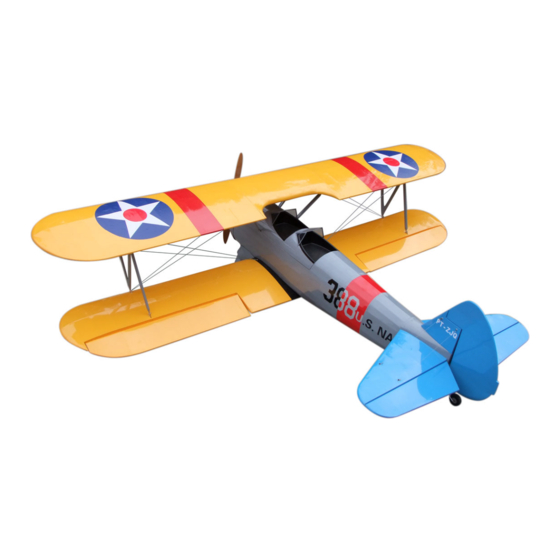
Boeing Stearman PT-17
Specification:
Length
: 1854mm(73〞)
Upper wing span: 2438mm(96〞)
Lower wing span: 2388mm(94〞)
Upper wing area: 86sq.dm (9.2sq.ft)
Lower wing area: 87.5sq.dm (9.4sq.ft)
Wing loading
: 77.8g/sq.dm(25.5oz/sq.ft)
Flying weight
: 13.5kg(29.7lbs)
Radio
: 6ch & 6servos
Engine
: 100cc
SAFETY PRECAUTIONS
INSTRUCTION MANUAL
This R/C airplane is not a toy!
(The people under 18 years old is forbidden from flying this model)
First-time builders should seek advice from people having building
experience.If misused or abused,it can cause serious bodily injury
and damage to property.
Fly only in open areas and preferably at a dedicated R/C flying site.
We suggest having a qualified instructor carefully inspect your
airplane before its first flight.Please carefully read and follow all
instructions included with this airplane,your radio control system
and any other components purchased separately.
Advertisement

Related Manuals for E-FLITE Boeing Stearman PT-17


Summary of Contents for E-FLITE Boeing Stearman PT-17
- Page 1 Boeing Stearman PT-17 Specification: Length : 1854mm(73〞) Upper wing span: 2438mm(96〞) Lower wing span: 2388mm(94〞) Upper wing area: 86sq.dm (9.2sq.ft) Lower wing area: 87.5sq.dm (9.4sq.ft) Wing loading : 77.8g/sq.dm(25.5oz/sq.ft) Flying weight : 13.5kg(29.7lbs) INSTRUCTION MANUAL Radio : 6ch & 6servos...
- Page 2 The front view when the install completion. (with 8 servos), 6 channel radio for aiplane is highly recommended for this model. The top view when the install completion. : 4-cycle .120 Spinner nut " Pre-cover the covering with clean cloth! Warning Start at low setting.
- Page 3 Boeing Stearman PT-17 packing list Adjustment of the elevator,be sure it can work perfectly. Adjustment of the rudder, be sure it can work perfectly. Cockpit Fuselage Side View RUDDER ELEVATOR Top view 50mm Top view 50mm 60mm 60mm landing gear cover...
-
Page 4: Table Of Contents
Fix the fuselage top cover to the fuselage with screws as Cut off the suplus from the cowl to fit the engine well. Boeing Stearman PT-17 packing list illustration. Package1 Package4 TP Screw (2.3x12mm) Steel wire (0.5x900mm) Screw (6x45mm) Steel wire (0.5x350mm) Screw (6x35mm) Steel wire (0.5x1700mm) - Page 5 Apply instant type AB glue to appropriate position in the Fix the landing gear to the fuselage with screws from the fuselage as illustration. Accessory list for the coming installation steps. trailing edge and assemble the ailerons to them. Screw (6x15mm) Rod (2.5x300mm) Washer (6x12mm) TP Screw (2.3x12mm)
-
Page 6: Tp Screw (2.3X12Mm)
Assemble the cover plate to the fuselage with screws. Apply instant type AB glue to the control horn and the slots in the aileron, Epoxy the wheel pants to the undercarriage as illustration. The standard sketch map when the kit install completion. insert the control horn to the slots as illustration. -
Page 7: Screw (3X10Mm)
Fix the lower wing to fuselage with screws throught the Install the servo of the throttle. Assembly of the fuel tank. The sketch map when the upper wing assemble completion. holes applied in the wings and fuselage. Screw Set screw (3x4mm) Washer Washer (2mm) Washer (2mm) -
Page 8: Washer(3X6Mm)
Assemble the engine to the fuselage via the engine In order to fix the upper wings,assemble one side of the Assemble the throttle linkage. The sketch map of the steel wire using for the wings. aluminum plates to the center wing with screws as illustration. mount tubes and screws. - Page 9 Fix the wing struts of the centre wing to the centre connect the engine and muffler with telescopic pipe. The side view once the engine install completion. Fix the steel wire to the wings. wing & fuselage as illustration. Screw Washer Screw Screw (3x10mm)
- Page 10 Drill four holes at the diameters as shown for engine Assemble the elevators to the stabilizers via pivot & round hinges. Accessory list for the coming installation steps. Install the plastic tubes to the slot of the ply as illustration. mount.
-
Page 11: Nut(4Mm )
The sketch map of the steel wires for the rudder in the Fix the stabilizers to the tail fuselage via screws. Accessory list for the coming installation steps. Install the nylon control horn and connect the linkage. fuselage. Top view Screw (5x35mm) Linkage Stopper Screw... -
Page 12: Steel Wire (0.5X1700Mm)
Trim a slot and drill a hole in the rudder for helping According to the illustration below bend the tail landing Assemble the rudder to the stabilizer fin. Fix the steel wires in the stabilizer. assemble the tail landing to it. gear wire and cut off the surplus part.