Table of Contents
Advertisement
Quick Links
Horizon Hobby Deutschland GmbH
Futaba is a registered trademark of Futaba Denshi Kogyo Kabushiki Kaisha Corporation of Japan
DSM and DSM2 are trademarks or registered trademarks of Horizon Hobby, Inc. The Spektrum trademark is
used with permission of Bachmann Industries, Inc. Spektrum radios and accessories are exclusively available from
13353
®
© 2008 Horizon Hobby, Inc.
4105 Fieldstone Road
Champaign, Illinois 61822
(877) 504-0233
Horizon Hobby UK
Units 1-4 Ployters Rd
Staple Tye
Harlow, Essex
CM18 7NS
United Kingdom
Otto Hahn Str. 9a
25337 Elmshorn
Germany
Horizon Hobby, Inc.
www.E-fliteRC.com
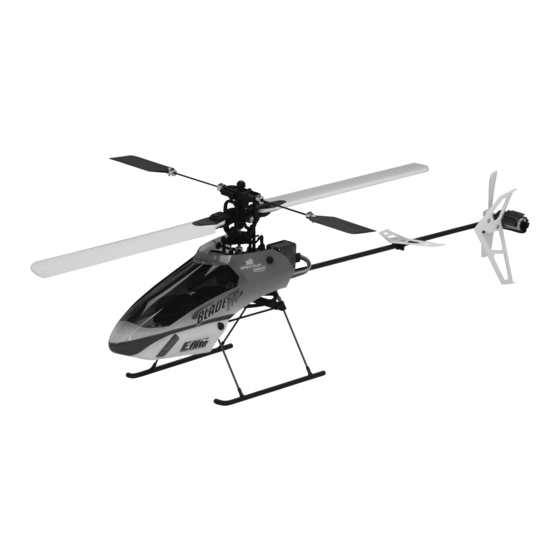
Specifications
Length . . . . . . . . . . . . . . . . . . . . . . . 20 .7 in (525mm)
Height . . . . . . . . . . . . . . . . . . . . . . . 7 .1 in (180mm)
Main Rotor Diameter . . . . . . . . . . . . . 20 .3 in (515mm)
Tail Rotor Diameter . . . . . . . . . . . . . . 3 .2 in (80mm)
Weight with Battery . . . . . . . . . . . . . . 11 .5 oz (325 g)
Main Motor . . . . . . . . . . . . . . . . . . . . .High-Power 370 (installed)
Tail Motor . . . . . . . . . . . . . . . . . . . . . Direct-Drive N60 (installed)
Battery . . . . . . . . . . . . . . . . . . . . . . . 3S 11 .1V 800mAh Li-Po (required)
Charger . . . . . . . . . . . . . . . . . . . . . . 3S 11 .1V Li-Po DC Balancing (required)
Transmitter . . . . . . . . . . . . . . . . . . . . 6+ channel with helicopter and 120-degree CCPM programming (required)
Receiver . . . . . . . . . . . . . . . . . . . . . . 6+ channel micro (required)
On-Board Electronics . . . . . . . . . . . . . 2-in-1 mixer/ESCs (installed)
Servos . . . . . . . . . . . . . . . . . . . . . . . DS75 Digital Sub-Micro (3 installed)
Gyro . . . . . . . . . . . . . . . . . . . . . . . . . G110 Micro Heading Lock (installed)
®
Advertisement
Table of Contents

Related Manuals for E-FLITE Blade CP Pro 2 PNP


Summary of Contents for E-FLITE Blade CP Pro 2 PNP
- Page 1 ® © 2008 Horizon Hobby, Inc. ® 4105 Fieldstone Road Champaign, Illinois 61822 (877) 504-0233 Specifications Horizon Hobby UK Units 1-4 Ployters Rd Length . . . . . . . . . . . . . . . . . . . . . . . 20 .7 in (525mm) Staple Tye Height .
-
Page 2: Table Of Contents
Additional Equipment ..........................5 micro CP class helicopter—right out of the box, no additional parts or upgrades required . The Blade CP Pro 2 PNP Recommended Setups . -
Page 3: Additional Safety Precautions And Warnings
As the user of this product, you are solely responsible for operating it in a manner that does not endanger yourself The following items are required to complete your Blade CP Pro 2 PNP: and others or result in damage to the product or the property of others . -
Page 4: Receiver Connection And Installation
Receiver Connection and Installation • Locate the wire leads/connectors located near the front of the main frame. While it is possible to connect these leads/connectors to the receiver after it’s been installed, it is easier to connect them to the receiver before A 6-channel or greater micro receiver is required . - Page 5 Transmitter Setup • After connecting the wire leads to the receiver, remove the remaining paper backing from the two-sided tape on the receiver . Then, carefully straighten the antenna(s) and place the receiver onto the front tray . Fasten the A 6-channel or greater transmitter with helicopter and 120-degree CCPM programming is required .
- Page 6 Swashplate Mixing (SWASH MIX) Throttle Hold (THRO HOLD) AILE +100% HOLD Pos . ELEV -100% HOLD SW 0 .0% PITC +35% Throttle Curves (THRO CURVE) In the “Setup” list (SETUP LIST): NOTE: The factory recommended normal mode throttle curve has been optimized for the power/torque band of Servo Reversing (REVERSE) the High-Power 370 and recommended brushless motor power system .
-
Page 7: Installing The Flight Battery
Slide the battery support and battery forward or rearward as required to achieve a slightly nose down or perfectly level helicopter position . You should always check the CG of your Blade CP Pro 2 PNP before flying, especially if you are switching between different sizes and types of battery packs . -
Page 8: Transmitter Control Identification
Transmitter Control Identification Control Test Note: Each time before you fly you should ALWAYS turn the transmitter on before connecting the flight battery to After programming your transmitter and installing the flight battery, it will be necessary to test the controls prior the 5-in-1 unit . - Page 9 Turn the transmitter on first and lower the throttle stick and trim completely . Then, plug the battery into the battery Position the helicopter to view it from the left or right side . Move the throttle/collective stick up and down to check lead of the 2-in-1 unit .
- Page 10 With the stick pulled back down, the swashplate should raise, decreasing the pitch of the main blades . Again viewing the helicopter from the left or right side, move the elevator stick forward and aft to check elevator pitch control . When the stick is pushed forward, the swashplate should also tilt forward . NOTE: HP6DSM Transmitter is shown for reference only .
- Page 11 With the stick pulled back, the swashplate will tilt toward the rear . While viewing the helicopter from the rear (tail boom toward you), move the right-hand stick left and right to check aileron roll control . When the stick is pushed to the left, the swashplate should also tilt left . NOTE: HP6DSM Transmitter is shown for reference only .
- Page 12 . However, if you continue to encounter any problems relating to your Blade CP Pro 2 PNP responding properly to the transmitter, do not fly . Call the Horizon Support Team at 1-877-504-0233 before proceeding .
-
Page 13: Servo Arm And Linkage Check And Adjustment
. Although the servo arms and linkages of each Blade CP Pro 2 PNP model have been assembled and installed at the factory, it may be necessary to make some small adjustments to achieve the proper and optimum control setup . -
Page 14: 2-In-1 Control Unit Description, Arming And Motor Control Test
Linkages After confirming that the swashplate is level and correctly positioned, and the main rotor blades are set to If you find that the swasplate is not positioned the correct amount from the top of the frame, or not level from any approximately 0 degrees of pitch, you are almost ready for the first flight . - Page 15 If this is the first test flight, or a test flight following repairs, you will also want to center the rudder, aileron and q After confirming that the transmitter has been turned on and has an adequate level of battery power as elevator trims .
-
Page 16: Gyro Initialization, Response Test And Adjustment
The G110 offers remote mode selection and gain adjustment features . These features allow the gyro mode Your Blade CP Pro 2 PNP model is equipped with an E-flite G110 Micro Heading Lock Gyro . This gyro offers an (Standard Rate or Heading Lock) and gain values to be set remotely in the transmitter . However, for simplified use, excellent blend of size, weight, features and performance . -
Page 17: Installing The Optional Training Gear
Installing the Optional Training Gear • Locate the four training gear rod to landing skid attachments. These are the black plastic parts with two relatively large holes in them . Slip the attachments around the landing gear struts (the “legs” that join the landing If the Blade CP Pro PNP 2 is your first single-rotor and/or collective-pitch equipped helicopter model, we suggest skids to the frame) from the inside, then snap the clips into place on the skids . -
Page 18: Understanding The Primary Flight Controls
. The rods will pass through the front holes of the forward attachments, and the back holes of the If you are not familiar with the controls of your Blade CP Pro 2 PNP, please take a few minutes to familiarize rear attachments . - Page 19 After lifting the model off the ground, you can balance the throttle/pitch by carefully moving the throttle stick up Moving the stick to the right will turn (yaw) the nose of the helicopter to the to the right about the axis of the main and down so the model will hold a stationary hover without climbing or descending .
- Page 20 Pulling the stick backward will pitch the tail of the helicopter downward, allowing the helicopter to be flown Moving the stick to the right will roll the helicopter to the right, allowing the helicopter to be flown to the right . backward .
-
Page 21: Normal And Stunt Flight Modes
Normal and Stunt Flight Modes In the idle up/stunt flight mode (Depending on which recommended settings you use), the throttle curve can be “V” shaped from 100% to 100% with 50% throttle at mid-stick or a “flat-line” from 100% to 100% with 100% throttle Your chosen transmitter should feature a Flight Mode switch . -
Page 22: Before The First Flight
+12° While it is possible for the Blade CP Pro 2 PNP to be flown indoors, we suggest that it only be in a very large indoor facility such as a gym that is also free of people and obstructions . The Blade CP Pro 2 PNP is not intended to be flown in small indoor areas or facilities where it may be possible to fly a coaxial helicopter like the Blade CX or Blade CX2 . -
Page 23: Flying The Blade Cp Pro 2 Pnp
. • It is extremely important when hovering and flying the Blade CP Pro 2 PNP to be aware of the power level of the Li-Po battery pack . If at any time the helicopter begins to require more throttle than typical to maintain hover... -
Page 24: Tail Rotor Proportional Mix Trimmer Pot Adjustment
Pro 2 PNP . Main rotor blades that are out of track may cause vibration, instability, and loss of power . Although each Blade CP Pro 2 PNP model is test flown and the blades are tracked at the factory, minor adjustments to blade tracking may be required after blade changes, repairs, or pitch control link adjustments . - Page 25 NOTE: The blade you choose to raise or lower when making tracking adjustments will depend on the pitch of Typically, not much adjustment should be necessary to properly track the main rotor blades . If significant each blade . Because both rotor blades should be as close to 0 degrees as possible when Throttle Hold is adjustments are required, be sure to double-check the length of both pitch control links (they should be close to activated (DO NOT attempt to check for 0 degrees pitch in the normal or stunt/idle up Flight Modes) and the the same length) .
-
Page 26: Flybar Paddle Tracking Adjustment
While main blade tracking is a critical element of flight performance, proper flybar paddle tracking and positioning Your Blade CP Pro 2 PNP is equipped with flybar weights that are secured in their outermost position against the is also important in maintaining proper control response and vibration-free operation . -
Page 27: Optional Brushless Main Motor Power System Installation And Setup
Pro Lite series 3S 11 .1V 910mAh battery (THP9103SJPL) . However, please note that the stock charger cannot be used with the 730mAh battery, and that a 3S 11 .1V Thunder Power to E-flite balance connector adapter cable (included with EFLA229) is necessary to allow use of the stock charger with the 910mAh battery . - Page 28 NOTE: Do not use the screws included with the brushless motor for mounting as they do not offer • After installing the adapter ring, it will then be necessary to remove the stock brushed main motor from the main frame in order to trial fit the brushless motor to check for proper placement of the pinion on the brushless adequate thread length for secure installation.
- Page 29 • Once the Y-harness has been connected to the ESC’s battery power leads, and the joints have been properly • After securing the ESC in its mounting position, connect the motor wire leads to the connectors on the ESC. insulated, you can now proceed with installation of the ESC on the helicopter . There are a few places in which The order of the wire leads in the connectors is not too important at this time, as the position of any two of the ESC can be mounted on the helicopter, including the following: them can be reversed if the motor does not spin in the proper direction after testing its operation .
- Page 30 • Turn the transmitter on first and advance the throttle stick to full power. Then, after placing your hand on the Your Blade CP Pro 2 PNP is now ready to fly with the optional brushless main motor power system . Be sure...
-
Page 31: 2008 Official Ama National Model Aircraft Safety Code
2008 Official AMA National Model Aircraft Safety Code 10 . The operator of a radio-controlled model aircraft shall control it during the entire flight, maintaining visual contact without enhancement other than by corrective lenses that are prescribed for the pilot . No model aircraft shall be equipped with devices which allow it to be flown to a selected location which is beyond the visual range of the GENERAL pilot . -
Page 32: Exploded View Parts Listing
Battery Support (1) EFLH1154 Front Battery Support Rod (2) EFLH1154 www.E-fliteRC.com Please see your favorite retailer or visit our web site ( ) to find the latest in new replacement and option parts releases for your Blade CP Pro 2 PNP. -
Page 33: Replacement Parts
Replacement Parts Optional Parts List EFLB0996 800mAh 3S 11.1V 15C Li-Po, 20GA JST/Balance EFLC3105 3-Cell Li-Po Balancing Charger, 0.8A EFLA229 Adapter Cables for THP Battery to EFL Balancer/Charger EFLH1032 2-in-1 Control Unit, Mixer/High-Power ESCs: BCPP2 EFLC4000 100-240V AC to 12VDC, 1.5 Amp Power Supply EFLH1056 HP6DSM 6-Channel Transmitter, 2.4GHz DSM2: BCPP2 EFLH1000... - Page 34 Warranty Period: Questions, Assistance, and Repairs Horizon Hobby, Inc ., (Horizon) warranties that the Products purchased (the “Product”) will be free from defects in Your local hobby store and/or place of purchase cannot provide warranty support or repair . Once assembly, materials and workmanship at the date of purchase by the Purchaser .
- Page 35 United States: NOTES Electronics and engines requiring inspection or repair should be shipped to the following address: Horizon Service Center 4105 Fieldstone Road Champaign, Illinois 61822 All other products requiring warranty inspection or repair should be shipped to the following address: Horizon Support Team 4105 Fieldstone Road Champaign, Illinois 61822...
- Page 36 NOTES NOTES...