Table of Contents
Advertisement
Quick Links
Advertisement
Table of Contents

Related Manuals for E-FLITE PT-19 ARF


Summary of Contents for E-FLITE PT-19 ARF
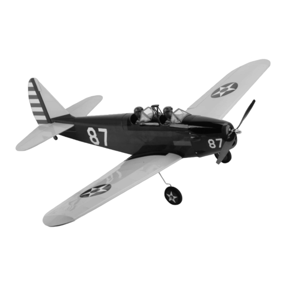
- Page 1 PT-19 ARF Assembly Manual Specifications Wingspan: 45 in (1440mm) Length: 36 in (910mm) Wing Area: 310 sq in (19.9 sq dm) Weight w/o Battery: 22–24 oz (680–740 g) Weight w/Battery: 27–29 oz (820–880 g) Pilots not included (available separately)
-
Page 2: Table Of Contents
Covering Colors ............2 performed once, while steps with two circles ( ) Recommended Radio Equipment, E-flite’s version of the PT-19 is a scale, almost-ready- indicate that the step will require repeating, such as for Radio Controlled Version ........3 to-fly, electric model designed for radio control with a right or left wing panel, two servos, etc. -
Page 3: Recommended Radio Equipment, Radio Controlled Version
If you own a Spektrum radio, just add a DSM2 ™ Felt-tipped pen Rubber bands (optional) Li-Po Charger receiver and four E-flite S75 Sub-Micro servos. We Heat gun Sealing iron EFLC505 Intelligent 1- to 5-Cell show the installation of the AR6100 receiver in the... -
Page 4: Warning
2mm x 8mm sheet metal screw (8) Required Tools and Adhesives Phillips screwdriver: #1 Pliers During the course of building your PT-19 ARF we Low-tack tape suggest that you use a soft base for the building surface. Such things as a foam stand, large piece of... - Page 5 4. Locate the aileron cover for the control line version of your model. Insert the brass pushrod connector into the outside hole of the control line aileron servo cover. Use a pushrod connector backplate and pliers to secure the connector. E-flite PT-19 ARF Assembly Manual...
-
Page 6: Aileron Servo And Linkage Installation Rc Option
1. Use the radio system to center the aileron servos. Use a #0 Phillips screwdriver to remove the control horns and install them on the servos as shown. Prepare a left and right aileron servo at this time. E-flite PT-19 ARF Assembly Manual... - Page 7 If so, you will need to adjust the position of the servo to make sure both blocks will be on the servo cover. 4. Carefully remove the servo cover from the wing panel. E-flite PT-19 ARF Assembly Manual...
- Page 8 11. Repeat the steps 2 through 10 to glue the blocks on the remaining servo cover at this time. Allow the epoxy to fully cure before proceeding. E-flite PT-19 ARF Assembly Manual...
- Page 9 If using string or dental floss to secure your servo lead, we place a very small drop of thin CA onto the knot to ensure it does not untie over time. E-flite PT-19 ARF Assembly Manual...
-
Page 10: Joining The Wing Panels, Rc And Cl Options
Once connected, remove the low tack tape from the aileron. 24. Repeat steps 12 through 23 to mount the remaining aileron servo to the servo cover and install the aileron linkage. E-flite PT-19 ARF Assembly Manual... - Page 11 Excess epoxy will ooze out of the joiner pocket as the joiner is inserted. If it does not, you have not used enough epoxy. Repeat steps 6 and 7 to apply more epoxy to the joiner and into the joiner pocket. E-flite PT-19 ARF Assembly Manual...
- Page 12 Use a third rubber band around the wing dowels. Always clean up any excess epoxy using a paper towel and rubbing alcohol. E-flite PT-19 ARF Assembly Manual...
-
Page 13: Landing Gear Installation Rc/Cl Options
Press the gear into the block so it is flush with amount of material from the landing gear block the bottom of the wing. allowing the wire gear to fully seat in the block. E-flite PT-19 ARF Assembly Manual... -
Page 14: Stabilizer And Fin Installation Rc/Cl Options
The top will have the blind nuts, and the control horn will face to the bottom. 3. Repeat Steps 1 and 2 to install the remaining main landing gear to the bottom of the wing. E-flite PT-19 ARF Assembly Manual... - Page 15 8. Slide the tail assembly forward so it is resting in position at the rear of the fuselage as shown below. E-flite PT-19 ARF Assembly Manual...
-
Page 16: Rudder Servo Installation Cl Option
They only need to be tight enough to prevent the assembly from moving when it is installed. Always use threadlock on metal-to-metal fasteners to prevent them from vibrating loose. E-flite PT-19 ARF Assembly Manual... - Page 17 CL before or it has been a long time since that last flight. You can reduce this over time to meet the personalized feel and performance of your PT-19. E-flite PT-19 ARF Assembly Manual...
-
Page 18: Rudder Servo Installation Rc Option
Set the cockpit hatch aside. 3. Insert the brass pushrod connector into the hole drilled in the previous step. Use pliers and the connector backplate to secure the brass pushrod connector to the servo arm. E-flite PT-19 ARF Assembly Manual... - Page 19 1/16-inch (1.5mm) drill bit to drill a hole screwdriver to tighten the screws. Slide the pushrod pushrod connector. in the servo tray at the position marked in the into the pushrod connector at this time. previous step. E-flite PT-19 ARF Assembly Manual...
-
Page 20: Elevator Bellcrank Installation Cl Option
Also cut a slit in the left wing tip for the leadout wire guide to fit into the wing. E-flite PT-19 ARF Assembly Manual... - Page 21 This will provide good solid control inputs for your first flights. Later on, you may move to the outside hole for even more throw if you so wish. E-flite PT-19 ARF Assembly Manual...
-
Page 22: Elevator Servo Installation Rc Option
4-40 x 1/2-inch socket head screws and four #4 washers to secure the elevator servo tray inside the fuselage. Note that the opening for the servo faces to the left side of the fuselage. E-flite PT-19 ARF Assembly Manual... - Page 23 Use a #1 Phillips screwdriver to connector to the servo arm. previous step. tighten the screws. E-flite PT-19 ARF Assembly Manual...
-
Page 24: Receiver Installation Rc Option
2. Apply the remaining side of the hook and loop tape from Step 1 to the radio tray as shown. This is done through the wing opening. E-flite PT-19 ARF Assembly Manual... -
Page 25: Speed Control Installation, Rc/Cl Options
Required Tools and Adhesives Scissors We show the installation of the E-flite 30A and 40A Pro SB ESC in the photos. We recommend the 40Amp Lite Pro SB ESC for the Park 480 option. Either 40A ESC can be used. The 40A lite is mounted similar to the 30A ESC. -
Page 26: Motor Installation Rc/Cl Options
Phillips screwdriver. Make sure to use threadlock on the screws to prevent them from vibrating loose. If flying control line it is common to program the ESC brake to On. The PT-19 has been operated in either configuration successfully. E-flite PT-19 ARF Assembly Manual... -
Page 27: Cowling And Propeller Installation, Rc/Cl Options
Always check the can be positioned for a variety of motors. Position the motor without the propeller to avoid injury. blind nuts so they are aligned with your particular motor before mounting the motor to the firewall. E-flite PT-19 ARF Assembly Manual... - Page 28 Make sure the pieces of card stock are positioned and with the cowl mounting plates that are inside on the outside of the cowl. the fuselage. E-flite PT-19 ARF Assembly Manual...
- Page 29 If it is necessary to enlarge the hole in the propeller or the spinner, make sure to check the balance of each afterwards. 12. Slide the propeller onto the propeller adapter. E-flite PT-19 ARF Assembly Manual...
-
Page 30: Motor Battery Placement Rc/Cl Options
The position of the battery can be adjusted to the front or rear of the fuselage as necessary to adjust the Center of Gravity when balancing the aircraft for flight. E-flite PT-19 ARF Assembly Manual... -
Page 31: Wing Installation, Rc/Cl Options
4-40 x 1-inch socket head on the leadout guide. bolts and two #4 washers that secure the wing to the fuselage. E-flite PT-19 ARF Assembly Manual... - Page 32 Insert 3/4 oz of wing tip. weight into the box for the first control line flights. We use three Sig lead balancing weights (1/4 oz each) inside the box to laterally balance the model for control line flying. E-flite PT-19 ARF Assembly Manual...
-
Page 33: Pilot Installation (Optional) Rc/Cl Options
RC/CL Options 1. Turn on the transmitter and receiver of your Required parts PT-19 ARF. Check the movement of the rudder Battery hatch Military pilots (1 or 2) using the transmitter. When the stick is moved right, Tools and adhesives the rudder should also move right. -
Page 34: Center Of Gravity
Elevator Low Rate When balancing your PT-19 ARF, support the plane 3/8-inch (10mm) Before each flying session, be sure to range check your... -
Page 35: Range Test Your Radio
You may vary the amount of weight at your discretion to fine-tune the flight qualities of your PT-19. 3. Be sure that your transmitter batteries are fully charged, per the instructions included with your radio. E-flite PT-19 ARF Assembly Manual... - Page 36 Landings are easily guided down as well. Please note the diagrams showing wing direction and placement for takeoff and maneuvering as the wind plays a major part in line tension during these maneuvers. E-flite PT-19 ARF Assembly Manual...
- Page 37 Failure to do so may cause you to lose control of your model possibly resulting in a crash and damage to the model. E-flite PT-19 ARF Assembly Manual...
-
Page 38: Safety, Precautions And Warnings
Product. This warranty does not cover damage due to improper installation, operation, maintenance, or attempted repair by anyone other than Horizon. Return of any goods by Purchaser must be approved in writing by Horizon before shipment. E-flite PT-19 ARF Assembly Manual... - Page 39 877.504.0233 toll free to speak to a service MasterCard, American Express, and Discover cards. technician. If you choose to pay by credit card, please include your credit card number and expiration date. Any E-flite PT-19 ARF Assembly Manual...
-
Page 40: Instructions For Disposal Of Weee By Users In The European Union
In the case of airshows demonstrations straight line must be established. An area away from the line must be maintained for spectators. Intentional flying behind the line is prohibited. E-flite PT-19 ARF Assembly Manual... - Page 41 No model aircraft shall be equipped with devices which allow it to be flown to a selected location which is beyond the visual range of the pilot. E-flite PT-19 ARF Assembly Manual...
-
Page 42: Building And Flying Notes
Building and Flying Notes E-flite PT-19 ARF Assembly Manual... -
Page 43: Building And Flying Notes
Building and Flying Notes E-flite PT-19 ARF Assembly Manual... - Page 44 © 2009 Horizon Hobby, Inc. 4105 Fieldstone Road Champaign, Illinois 61822 (877) 504-0233 horizonhobby.com E-fliteRC.com Printed 01-09 14769...