
Related Manuals for E-FLITE Carbon-Z P2 Prometheus


Summary of Contents for E-FLITE Carbon-Z P2 Prometheus
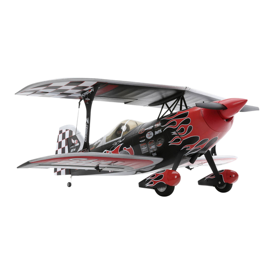
- Page 1 ® Carbon-Z Prometheus Instruction Manual Bedienungsanleitung Manuel d’utilisation Manuale di Istruzioni...
-
Page 2: Safety Precautions And Warnings
NOTICE All instructions, warranties and other collateral documents are subject to change at the sole discretion of Horizon Hobby, LLC. For up-to-date product literature, visit www.horizonhobby.com and click on the support tab for this product. Meaning of Special Language: The following terms are used throughout the product literature to indicate various levels of potential harm when operating this product: NOTICE: Procedures, which if not properly followed, create a possibility of physical property damage AND little or no possibility of injury. -
Page 3: Table Of Contents
Box Contents Quick Start Information Blank (Acro) Model Transmitter Servo Reversing: Normal Setup Travel Adjust (All Surfaces): 100% Hi Rates Low Rates 100% Dual Rates* 100% 125% High EXPO* Center of 5.2 inches (132 mm) back from the leading Gravity (CG) edge of top wing at the center. -
Page 4: Prefl Ight
Prefl ight Remove and inspect contents. Perform the Control Direction Test with the transmitter. Read this instruction manual thoroughly. 10 Perform the AS3X Control Direction Test with the aircraft. Charge the fl ight battery. 11 Adjust fl ight controls and transmitter. Fully assemble the airplane. -
Page 5: Rudder Installation
Model Assembly Continued Required Adhesives: Thin CA Rudder Installation 1. Slide the rudder’s CA hinges (A) in the hinge slots (B) of the vertical tail. 2. Install the screw (C) in the rudder mount. 3. Rest the aircraft on its nose, holding the tail up so the thin CA (cyanoacrylate adhesive) will flow into the slots. -
Page 6: Horizontal Stabilizer Installation
Model Assembly Continued Rudder Installation Continued 7. Attach the Z-bend (E) of the control linkage to the servo arm’s outermost hole, with the Z-bend facing in as shown. 8. Ensure the rudder servo arm is in the correct position and the rudder is centered, then snap the ball link (F) onto the ball of the rudder control horn (G). -
Page 7: Wing Installation
Model Assembly Continued Horizontal Stabilizer Installation Continued 4. Remove the screw securing the servo arm and remove the servo arm. 5. Attach the Z-bend end (D) of the control linkage to the servo arm’s outer most hole with the Z-bend facing out as shown. 6. - Page 8 Model Assembly Continued Wing Installation Continued 5. In the fuselage, locate the 2 screw holes (B) at the bottom of the 20mm (2) fuselage. Use the 2 included screws (C) to secure the wings into place. CAUTION: DO NOT crush or otherwise damage the wiring when attach- ing the wing to the fuselage.
- Page 9 Model Assembly Continued Wing Installation Continued Top Wing Placement Continued 15mm (2) 3. Secure the top wing asembly to the center strut bracket with the 2 included screws (B). 4. Install the left and right wing struts (C) by sliding them into position decals facing out.
- Page 10 Model Assembly Continued Wing Installation Continued Aileron connecting rod installation 1. Install the aileron connecting rod (A) to the upper aileron by snapping the ball link onto the ball. 2. Center the lower aileron and adjust the lower ball link as needed so the top aileron is centered.
-
Page 11: Motor And Propeller Installation
Model Assembly Continued Motor and Propeller Installation 1. Install the collet (A), drive washer (B) and spinner backplate (C) on the motor shaft (D). 2. Install the propeller (E) propeller washer (F), and propeller nut (G) on the prop shaft. 3. -
Page 12: Control Surface Centering
Control Surface Centering After assembly and transmitter setup, confi rm that the control surfaces are centered. If the control surfaces are not centered, mechanically center the control surfaces by adjusting the linkages. After binding a transmitter to the aircraft receiver, set the trims and sub-trims to 0, then adjust the linkages to center the control surfaces. -
Page 13: Transmitter And Receiver Binding
Receiver Selection and Installation The Spektrum AR636 receiver is recommended for this airplane. If you choose to install another receiver, ensure that it is at least a 6-channel full range (sport) receiver. Refer to your receiver manual for correct installation and operation instructions. -
Page 14: Battery Installation And Esc Arming
Battery Installation and ESC Arming Battery Selection We recommend the E-fl ite ® 4400mAh 22.2V 6S 30C Li-Po battery (EFLB44006S30). Refer to the Optional Parts List for other recommended batteries. If using a battery other than those listed, the battery should be within the range of capacity, dimensions and weight of the E-fl... -
Page 15: Center Of Gravity (Cg)
Center of Gravity (CG) The CG location is measured forward from the trailing edge of the top wing, at the center. This CG location has been determined with the recommended battery (EFLB44006S30), with the model balanced upright. Adjust the battery forward or aft as needed to achieve the proper CG location. -
Page 16: In Flight Trimming
In Flight Trimming During your fi rst fl ight, trim the aircraft for level fl ight at 3/4 throttle. Make 3 Seconds small trim adjustments with your transmitter’s trim switches to straighten the aircraft’s fl ight path. After adjusting trim do not touch the control sticks for 3 seconds. This al- lows the receiver to learn the correct settings to optimize AS3X performance. -
Page 17: Post Flight Checklist
Post Flight Checklist Disconnect the fl ight battery from the ESC (Required for Safety Repair or replace all damaged parts. and battery life). Store the fl ight battery apart from the aircraft and monitor the Power OFF the transmitter. battery charge. Remove the fl... -
Page 18: Troubleshooting Guide
Troubleshooting Guide Problem Possible Cause Solution Throttle not at idle and/or throttle trim too high Reset controls with throttle stick and throttle trim at lowest setting Aircraft will not re- Throttle servo travel is lower than 100% Make sure throttle servo travel is 100% or greater spond to throttle but responds to other Throttle channel is reversed... -
Page 19: Ama National Model Aircraft Safety Code
AMA National Model Aircraft Safety Code Effective January 1, 2014 A. GENERAL B. RADIO CONTROL A model aircraft is a non-human-carrying aircraft capable of sustained fl ight 1. All pilots shall avoid fl ying directly over unprotected people, vessels, in the atmosphere. It may not exceed limitations of this code and is intended vehicles or structures and shall avoid endangerment of life and property exclusively for sport, recreation, education and/or competition. -
Page 20: Limited Warranty
Limited Warranty What this Warranty Covers protection. Ship via a carrier that provides tracking and insurance for lost or Horizon Hobby, LLC, (Horizon) warrants to the original purchaser that the damaged parcels, as Horizon is not responsible for merchandise until it arrives product purchased (the “Product”) will be free from defects in materials and and is accepted at our facility. -
Page 21: Contact Information
Contact Information Country of Purchase Horizon Hobby Phone Number/Email Address Address Horizon Service Center servicecenter.horizonhobby.com/ (Repairs and Repair Requests) RequestForm/ productsupport@horizonhobby.com Horizon Product Support United States of 4105 Fieldstone Rd (Product Technical Assistance) 888-959-2305 America Champaign, Illinois, 61822 USA sales@horizonhobby.com Sales 888-959-2305 sales@horizonhobby.co.uk... -
Page 22: Replacement Parts
Replacement Parts • Ersatzteile • Pièces de rechange • Pezzi di ricambio Part # | Nummer Description Beschreibung Description Descrizione Numéro | Codice EFL10902 Decal; Set: P2 Decal; Satz: P2 Autocollant ; Lot : P2 Set decalcomanie: P2 EFL10904 Spinner: P2 Spinner: P2 Cône : P2 Ogiva: P2... - Page 23 © 2016 Horizon Hobby, LLC. E-fl ite, Carbon-Z, AS3X, DSM, DSM2, DSMX, the DSMX logo, Bind-N-Fly, the BNF logo, Plug-N-Play, Z-Foam, ModelMatch, EC3, EC5, Dynamite, Passport and the Horizon Hobby logo are trademarks or registered trademarks of Horizon Hobby, LLC. The Spektrum trademark is used with permission of Bachmann Industries, Inc.