Interlogix NS3562-8P-2S User Manual
Hide thumbs
Also See for NS3562-8P-2S:
- Quick installation manual (4 pages) ,
- Quick installation manual (4 pages)
Table of Contents
Advertisement
Quick Links
Advertisement
Table of Contents

Related Manuals for Interlogix NS3562-8P-2S


Summary of Contents for Interlogix NS3562-8P-2S
- Page 1 NS3562-8P-2S User Manual P/N 1073225-EN • REV B • ISS 01MAR19...
- Page 2 Copyright © 2019 United Technologies Corporation. Interlogix is part of UTC Climate, Controls & Security, a unit of United Technologies Corporation. All rights reserved. Trademarks and patents Trade names used in this document may be trademarks or registered trademarks of the manufacturers or vendors of the respective products.
-
Page 3: Table Of Contents
Access Control Lists (ACL) 174 MAC address table 185 LLDP 187 Diagnostics 198 RMON 202 Power over Ethernet (PoE) 209 Maintenance 217 Chapter 5 Switch operation 221 Address table 221 Learning 221 Forwarding and filtering 221 Store-and-forward 221 Auto-negotiation 222 NS3562-8P-2S User Manual... - Page 4 Chapter 6 PoE overview 223 What is PoE? 223 PoE system architecture 223 Chapter 7 Troubleshooting 225 Appendix A Networking connection 226 Glossary 228 NS3562-8P-2S User Manual...
-
Page 5: Important Information
Note: Note messages advise you of the possible loss of time or effort. They describe how to avoid the loss. Notes are also used to point out important information that you should read. NS3562-8P-2S User Manual... -
Page 6: Introduction
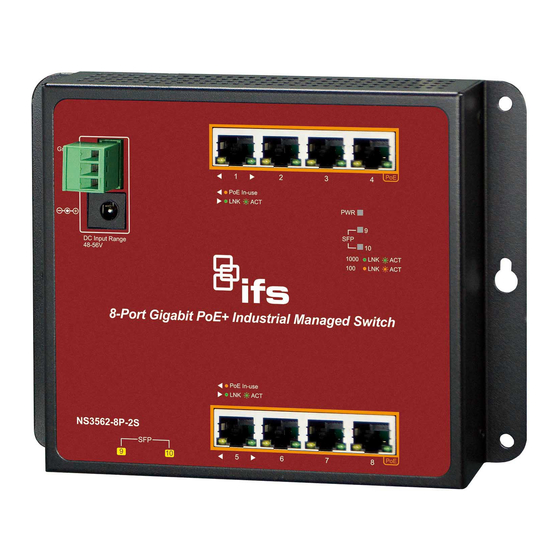
Chapter 1 Introduction The description of the IFS NS3562-8P-2S model is as follows: Industrial L2+ 8-port 10/100/1000T 802.3at PoE+ + 2-port 100/1000X SFP wall-mount managed switch Unless specified, the term “industrial managed switch” mentioned in this user manual refers to the NS3562-8P-2S. - Page 7 16 Gbps fat pipe, and also supports fail-over. Also, the Link Layer Discovery Protocol (LLDP) is the Layer 2 protocol included to help discover basic information about neighboring devices on the local broadcast domain. NS3562-8P-2S User Manual...
- Page 8 PoE port power and puts the PD back to work. The industrial managed switch greatly enhances the network reliability through the PoE port resetting the PD’s power source and reducing the administrator management burden. NS3562-8P-2S User Manual...
- Page 9 PoE power feeding for each PoE port during specified time intervals, and is a powerful function to help SMBs or enterprises save power and money. It also increases security by powering off PDs that should not be in use during non-business hours. NS3562-8P-2S User Manual...
-
Page 10: Product Features
Complies with IEEE 802.3at High Power over Ethernet end-span/mid-span PSE. • Complies with IEEE 802.3af Power over Ethernet end-span PSE. • IEEE 802.3af/IEEE 802.3at devices powered. • Supports PoE power up to 36 W for each PoE port. NS3562-8P-2S User Manual... - Page 11 STP, IEEE 802.1D Spanning Tree Protocol • RSTP, IEEE 802.1w Rapid Spanning Tree Protocol • MSTP, IEEE 802.1s Multiple Spanning Tree Protocol, spanning tree by VLAN • BPDU Guard Supports link aggregation • IEEE 802.3ad Link Aggregation Control Protocol (LACP) NS3562-8P-2S User Manual...
- Page 12 Dynamic ARP inspection discards ARP packets with invalid MAC addresses to IP address binding. • IP source guard prevents IP spoofing attacks. • Auto DoS rule to defend against DoS attacks. • IP address access management to prevent unauthorized intruders. NS3562-8P-2S User Manual...
-
Page 13: Product Specifications
PoE Injector Ports Eight ports with 802.3at/af PoE injector function (Port-1 to Port-8) Switch Architecture Store-and-Forward Switch Fabric 20 Gbps / non-blocking Throughput 14.8 Mpps @ 64 bytes Address Table 8K entries Shared Data Buffer 4.1 Mbits NS3562-8P-2S User Manual... - Page 14 48~56 DC, 5A (max.) DC jack power input Power Requirement Note: These two power input interfaces don’t support the power redundant feature. Power Consumption Max 210 W / 716 BTU Contact discharge: 6K VDC ESD Protection Air discharge: 8K VDC Power Over Ethernet NS3562-8P-2S User Manual...
- Page 15 Traffic classification based, strict priority and WRR 8-level priority for switching – Port number – 802.1p priority – 802.1Q VLAN tag – DSCP/ToS field in IP packet IGMP Snooping IGMP (v1/v2/v3) snooping, up to 256 multicast groups NS3562-8P-2S User Manual...
- Page 16 RFC 1493 Bridge MIB RFC 2674 Bridge MIB Extensions SNMP MIBs RFC 2737 Entity MIB (version 2) RFC 2819 RMON (1, 2, 3, 9) RFC 2863 Interface Group MIB RFC 3635 Ethernet-like MIB Environment Operating Temperature: -40 to 75°C NS3562-8P-2S User Manual...
- Page 17 Chapter 1: Introduction Relative Humidity: 5 to 95% (non-condensing) Temperature: -40 to 75°C Storage Relative Humidity: 5 to 95% (non-condensing) NS3562-8P-2S User Manual...
-
Page 18: Installation
LED indicators. Before connecting any network device to the industrial managed switch, please read this chapter completely. Hardware description The industrial managed switch provides three different running speeds – 10Mbps, 100Mbps, and 1000Mbps, and automatically distinguishes the speed of the incoming connection. NS3562-8P-2S User Manual... - Page 19 Chapter 2: Installation Physical dimensions Dimensions (W x D x H): 178 x 25 x 134 mm NS3562-8P-2S User Manual...
- Page 20 48~56 VDC 48~56 VDC To install the 3-pin terminal block connector on the wall-mount managed switch: 1. Insert the positive DC power wire into V+, negative DC power wire into V-, and the grounding wire into Ground. NS3562-8P-2S User Manual...
- Page 21 Powered Device (PD). Per 100/1000X SFP interface (Port-9 to Port-10) Color Function Green Lit: indicates the port has successfully connected to the 1000 LNK/ACT network at 1000 Mbps. Blinking: indicates that the switch is actively sending or NS3562-8P-2S User Manual...
-
Page 22: Installing The Industrial Managed Switch
Hot-swapping this device will result in damage. DIN-rail mounting Note: Follow all the DIN-rail installation steps as shown in the example. To install the DIN rails on the industrial managed switch: 1. Screw the DIN-rail onto the industrial managed switch. NS3562-8P-2S User Manual... - Page 23 2. Install a conductor pipe inside the board hole and flush the edge of the conductor pipe with the wall surface. 3. Screw the bolts into the conductor pipe. The switch is between the bolts and the conductor pipe, as shown below. NS3562-8P-2S User Manual...
-
Page 24: Cabling
10/100/1000BASE-T ports, and then turn on the industrial managed switch. The port will automatically run in 10 Mbps, 20 Mbps, 100 Mbps, or 200 Mbps, and 1000 Mbps or 2000 Mbps after negotiating with the connected device. NS3562-8P-2S User Manual... - Page 25 Installing the SFP/SFP+ transceiver SFP transceivers are hot-pluggable and hot-swappable. They can be plugged in and removed to/from any SFP port without having to power down the industrial managed switch (see below). NS3562-8P-2S User Manual...
- Page 26 Chapter 2: Installation Approved Interlogix SFP transceivers The industrial managed switch supports both single mode and multi-mode SFP transceivers. The following list of approved Interlogix SFP transceivers is valid as of the time of publication: Optical Optical Receiver Fiber # of...
- Page 27 0 to +50°C -8 ~ -2 Mode (12 mi.) 1490 nm (32 to 122°F) S30-1SLC/B- Single 20 km 1490 / 0 to +50°C -8 ~ -2 Mode (12 mi.) 1310 nm (32 to 122°F) Gigabit Ethernet 1000 Base BX NS3562-8P-2S User Manual...
- Page 28 * Note: High Power Optic. There must be a minimum of 5 dB of optical loss to the fiber for proper operation. Note: We recommend the use of Interlogix SFPs on the industrial managed switch. If you insert an SFP transceiver that is not supported, the industrial managed switch will not recognize it.
- Page 29 Never pull out the module without making use of the lever or the push bolts on the module. Removing the module with force could damage the module and the SFP/SFP+ module slot of the industrial managed switch. NS3562-8P-2S User Manual...
-
Page 30: Switch Management
We recommend the use of Internet Explorer 11.0 or later to access the industrial managed switch. Management access overview The industrial managed switch provides the flexibility to access and manage it using any or all of the following methods: • Web browser interface • An external SNMP-based network management application NS3562-8P-2S User Manual... -
Page 31: Web Management
Microsoft Internet Explorer. After setting up the IP address for the switch, you can access the industrial managed switch's web interface applications directly in the web browser by entering the IP address of the industrial managed switch. NS3562-8P-2S User Manual... -
Page 32: Snmp-Based Network Management
If there are two or more LAN cards in the same administrator computer, choose a different LAN card by using the “Select Adapter” tool. 3. Click the Refresh button for the currently connected devices in the discovery list: NS3562-8P-2S User Manual... - Page 33 Web Smart Switch under a different IP subnet address. 6. Click the Connect to Device button and the web login screen appears. 7. Click the Exit button to shut down the Smart Discovery Utility. NS3562-8P-2S User Manual...
-
Page 34: Web Configuration
If the default IP address of the industrial managed switch has been changed to 192.168.1.1 with subnet mask 255.255.255.0 via the console, then the administrator computer should be set at 192.168.1.x (where x is a number between 2 and 254) to do the relative configuration on a manager computer. NS3562-8P-2S User Manual... -
Page 35: Main Web
Note: For security purposes, change and memorize the new password after this first setup. Main web page This section describes how to use the industrial managed switch’s web browser interface for configuration and management. NS3562-8P-2S User Manual... - Page 36 The administrator can set up the industrial managed switch by making selections from the main functions menu. Clicking on a main menu item opens sub menus. NS3562-8P-2S User Manual...
- Page 37 The page includes the following fields: Item Function Save Configuration to FLASH Saves the configuration. See xxx Restore to Default Resets the switch to default parameters. See xxx NS3562-8P-2S User Manual...
- Page 38 To save all applied changes and set the current configuration as a startup configuration requires the startup-configuration file to be loaded automatically across a system reboot. NS3562-8P-2S User Manual...
-
Page 39: System
The industrial managed switch system log information is provided here. SNMP Management Configure SNMP parameters on this page. System information The System Infomation page provides information on the current device such as the hardware MAC address, software version, and system uptime. NS3562-8P-2S User Manual... - Page 40 IP configuration This page includes the IP address, subnet mask, and gateway. The configured column is used to view or change the IP configuration. Type in the IP address, subnet mask, and gateway as necessary. NS3562-8P-2S User Manual...
- Page 41 Buttons • Click Apply to apply changes. IPv6 configuration IP status displays the status of the IP protocol layer. The status is defined by the IP interfaces, the IP routes, and the neighbour cache (ARP cache) status. NS3562-8P-2S User Manual...
- Page 42 This page provides an overview of the current users. Close and reopen the browser to log in as another user on the web server. After setup is complete, click the Apply button and log in to the web interface with the new user name and password. The following appears: NS3562-8P-2S User Manual...
- Page 43 Object Description Username Dsiplays the current user name. Password Type Displays the current password type. Privilege Type Displays the current privilege type. Modify Click to modify the local user entry. Click Delete to delete the current user. NS3562-8P-2S User Manual...
- Page 44 Allows the user to input year value. (it supports from 1970 to 2037 only) Month Allows the user to input month value. (1 to 12 month). Allows the user to input day value. (1 to 31 days). Hour Allows the user to input hour value. (00 to 23 hours). NS3562-8P-2S User Manual...
- Page 45 The default is for event levels 0 to 3 are to be logged to flash and levels 0 to 6 are to be logged to RAM. The following table lists the event levels of the industrial managed switch: NS3562-8P-2S User Manual...
- Page 46 This page includes the following fields: Object Description Target The target of the local log entry. The following target types are supported: Buffered: Target the buffer of the local log. File: Target the file of the local log. NS3562-8P-2S User Manual...
- Page 47 The Remote Syslog page permits the configuration of the logging of messages that are sent to syslog servers or other management stations. You can also limit the event messages sent to only those messages below a specified level. NS3562-8P-2S User Manual...
- Page 48 Displays the current remote syslog server information. Severity Displays the current remote syslog severity. Displays the current remote syslog facility. Actions Click Delete to delete the remote server entry. Log message The switch log view is provided here: NS3562-8P-2S User Manual...
- Page 49 It is part of the Transmission Control Protocol/Internet Protocol (TCP/IP) protocol suite. SNMP permits network administrators to manage network performance, find and solve network problems, and plan for network growth. An SNMP-managed network consists of the following: NS3562-8P-2S User Manual...
- Page 50 An SNMP device or agent may belong to more than one SNMP community. It will not respond to requests from management stations that do not belong to one of its communities. SNMP default communities are: • Write (private) • Read (public) NS3562-8P-2S User Manual...
- Page 51 An optional flag to indicate that this view subtree should be included. excluded: An optional flag to indicate that this view subtree should be excluded. General, if a view entry's view type is 'excluded', it should exist NS3562-8P-2S User Manual...
- Page 52 Reserved for SNMPv2c. V3: Reserved for SNMPv3 or User-based Security Model (USM) Security Level Indicates the security model that this entry should belong to. Possible security models are: Noauth: None authentication and none privacy security levels are NS3562-8P-2S User Manual...
- Page 53 Display the current read view name Write View Name Display the current write view name Notify View Name Display the current notify view name Action Click Delete to delete the access group entry. SNMP community Configure the SNMP community on this page. NS3562-8P-2S User Manual...
- Page 54 Community Name Displays the current community type Group Name Displays the current SNMP access group’s name. View Name Displays the current view name. Access Right Displays the current access type Delete Click Delete to delete the community entry. NS3562-8P-2S User Manual...
- Page 55 DES: An optional flag to indicate that this user using DES authentication protocol. Encryption Key A string identifying the privacy pass phrase. The allowed string length is 8 to 16. Buttons • Click to add a new user entry. NS3562-8P-2S User Manual...
- Page 56 SNMP message via this port, the port range is 1~65535. Time Out Indicates the SNMP trap inform timeout. The allowed range is 1 to 300. Retries Indicates the SNMP trap inform retry times. The allowed range is 1 to 255. NS3562-8P-2S User Manual...
- Page 57 SNMP message via this port, the port range is 1~65535. Time Out Indicates the SNMP trap inform timeout. The allowed range is 1 to 300. Retries Indicates the SNMP trap inform retry times. The allowed range is 1 to 255. NS3562-8P-2S User Manual...
- Page 58 The string must contain an even number between 10 and 64 hexadecimal digits, but all-zeros and all-'F's are not allowed. Buttons • Click Apply to apply changes. SNMP remote engine ID Configure the SNMPv3 remote Engine ID on this page. NS3562-8P-2S User Manual...
-
Page 59: Port Management
Displays current bandwidth utilization Port Mirroring Sets the source and target ports for mirroring Jumbo Frame Sets the jumbo frame on the switch Port Error Disable Configures port error disable settings Configuration Port Error Disabled Status Disables port error status NS3562-8P-2S User Manual... - Page 60 The Rx and Tx settings are determined by the result of the last Auto-Negotiation. Check the configured column to use flow control. This setting is related to the setting for Configured Link Speed. Buttons • Click Apply to apply changes. NS3562-8P-2S User Manual...
- Page 61 This page provides an overview of general traffic and trunk statistics for all switch ports. The page includes the following fields: Object Description Port Select port number from this drop-down menu. Mode Select port counters mode. Options: Interface Ether-link RMON NS3562-8P-2S User Manual...
- Page 62 Transmit Broadcast The total number of packets that higher-level protocols requested is Packets transmitted, and addressed to a broadcast address at this sub-layer, including those that were discarded or not sent. NS3562-8P-2S User Manual...
- Page 63 The number of received and transmitted symbol errors Control In Unknown The number of received control unknown opcodes Opcodes In Pause Frames The number of received pause frames Out Pause Frames The number of transmitted pause frames NS3562-8P-2S User Manual...
- Page 64 The total number of frames received that were longer than 1518 octets (excluding framing bits, but including FCS octets), and had either an FCS or alignment error. Collisions The best estimate of the total number of collisions on this Ethernet segment. NS3562-8P-2S User Manual...
- Page 65 Bandwidth utilization statistics are represented with a line graph. The page includes the following fields: Object Description Refresh Period This shows the period interval between last and next refresh. Options: 2 sec 5 sec 10 sec Enable Disable this function. NS3562-8P-2S User Manual...
- Page 66 All frames received on a given port (also known as ingress or source mirroring). • All frames transmitted on a given port (also known as egress or destination mirroring). Mirror port configuration The page includes the following fields: NS3562-8P-2S User Manual...
- Page 67 Enter the maximum frame size allowed for the switch port, including FCS. The allowed range is 64 bytes to 9216 bytes. Buttons • Click Apply to apply changes. Port error disabled configuration Port error disable functions are configured on this page. NS3562-8P-2S User Manual...
- Page 68 Enable or disable the port error disabled function to check status by DHCP rate limit. ARP Rate Limit Enable or disable the port error disabled function to check status by ARP rate limit. Buttons • Click Apply to apply changes. NS3562-8P-2S User Manual...
- Page 69 Servers in a farm of web servers in a Demilitarized Zone (DMZ) are allowed to communicate with the outside world and with database servers on the inside segment, but are not allowed to communicate with each other. NS3562-8P-2S User Manual...
- Page 70 VLAN table is applied. When traffic comes in on an isolated port, the private VLAN mask is applied in addition to the VLAN mask from the VLAN table. This reduces the port forwarding to just the promiscuous ports within the private VLAN. NS3562-8P-2S User Manual...
-
Page 71: Link Aggregation
Link Aggregation Control Protocol (LACP) LAGs – LACP LAGs negotiate aggregated port links with other LACP ports located on a different device. If the other device ports are also LACP ports, the devices establish a LAG between them. NS3562-8P-2S User Manual... - Page 72 The ports at both ends of a connection must be configured as link aggregation ports. • None of the ports in a link aggregation can be configured as a mirror source port or a mirror target port. NS3562-8P-2S User Manual...
- Page 73 Address: The MAC address can be used to calculate the port for the frame. IP/MAC Address: The IP and MAC address can be used to calculate the port for the frame. Buttons • Click Apply to apply changes. LAG management Configure LAG management on this page. NS3562-8P-2S User Manual...
- Page 74 Displays the current type. Link State Displays the link state. Active Member Displays the active member. Standby Member Displays the standby member. Modify Click Edit to modify LAG configuration. LAG port setting Configure each LAG on this page. NS3562-8P-2S User Manual...
- Page 75 Check the configured column to use flow control. This setting is related to the setting for Configured Link Speed. Buttons • Click Apply to apply changes. LACP port setting Configure the LACP port setting on this page. NS3562-8P-2S User Manual...
- Page 76 LAG. This page allows the user to inspect and change the current LACP port configurations. The LACP port settings relate to the current device, as reflected by the page header. NS3562-8P-2S User Manual...
- Page 77 Displays the current LAG name. Type Displays the current trunk type. Link State Displays the current link state. Active Member Displays the current active member. Standby Member Displays the current standby member. The page includes the following fields: NS3562-8P-2S User Manual...
- Page 78 The contents could be true or false. If the contents are false, the web will show “_”; if the contents are true, the Web shows “A”, “T”, “G”, “S”, “C”, “D”, “F” and “E” for each content respectively. NS3562-8P-2S User Manual...
-
Page 79: Vlan
The industrial managed switch's default is to assign all ports to a single 802.1Q VLAN named DEFAULT_VLAN. As a new VLAN is created, the member ports assigned to the new VLAN are removed from the DEFAULT_ VLAN port member list. The DEFAULT_VLAN has a VID = 1. NS3562-8P-2S User Manual... - Page 80 Up to 255 VLANs based on the IEEE 802.1Q standard. • Port overlapping, allowing a port to participate in multiple VLANs. • End stations can belong to multiple VLANs. • Passing traffic between VLAN-aware and VLAN-unaware devices. NS3562-8P-2S User Manual...
- Page 81 VID is 12 bits long, 4094 unique VLAN can be identified. The tag is inserted into the packet header making the entire packet longer by four octets. All of the information originally contained in the packet is retained. NS3562-8P-2S User Manual...
- Page 82 A switch port can have only one PVID, but can have as many VIDs as the switch has memory in its VLAN table to store them. NS3562-8P-2S User Manual...
- Page 83 A group of network users assigned to a VLAN form a broadcast domain that is separate from other VLANs configured on the switch. Packets are forwarded only between ports that are designated for the same VLAN. Untagged VLANs can be used to manually isolate user groups or subnets. NS3562-8P-2S User Manual...
- Page 84 VLAN List Indicates the ID of this particular VLAN. VLAN Action This column allows users to add or delete VLANs. VLAN Name Prefix Indicates the name of this particular VLAN. Buttons • Click Apply to apply changes. NS3562-8P-2S User Manual...
- Page 85 VLAN IDs. This is accomplished by inserting Service Provider VLAN (SPVLAN) tags into the customer’s frames when they enter the service provider’s network, and then stripping the tags when the frames leave the network. NS3562-8P-2S User Manual...
- Page 86 In cases where a given service VLAN only has two member ports on the switch, the learning can be disabled for the particular VLAN and can therefore rely on flooding as the forwarding mechanism between the two ports. This way, the MAC table requirements are reduced. Edit interface setting NS3562-8P-2S User Manual...
- Page 87 However, the port will never transmit frames classified to VLANs that it is not a member of. Uplink Enable/disable uplink function in trunk port. TPID Configure the type (TPID) of the protocol of switch trunk port. Buttons • Click Apply to apply changes. NS3562-8P-2S User Manual...
- Page 88 VLAN or CoS information. Note that an interface must be assigned to at least one group as an untagged port. PVID Displays the current PVID. Buttons • Click Apply to apply changes. NS3562-8P-2S User Manual...
- Page 89 VLANs that divide the physical network into logical VLAN groups for each required protocol. When a frame is received at a port, its VLAN membership can then be determined based on the protocol type being used by the inbound packets. NS3562-8P-2S User Manual...
- Page 90 Valid value that can be entered in this text field depends on the option 0xFFFE) selected from the preceding Frame Type selection menu. Valid values for frame type ranges from 0x0600-0xfffe Buttons • Click Apply to apply changes. The page includes the following fields: NS3562-8P-2S User Manual...
- Page 91 VLAN port entry. The page includes the following fields: Object Description Port Displays the current port Group ID Displays the current group ID VLAN ID Displays the current VLAN ID Delete Click Delete to delete the group ID entry NS3562-8P-2S User Manual...
- Page 92 VLANs are dynamically configured based on join messages issued by host devices and propagated throughout the network. GVRP must be enabled to permit automatic VLAN registration, and to support VLANs which extend beyond the local switch. The page includes the following fields: NS3562-8P-2S User Manual...
- Page 93 VLANs running across the 802.1Q trunk link. If the device on the other side is not capable of sending GVRP messages, or if you do not want to allow the switch to prune any of the VLANs, use the fixed NS3562-8P-2S User Manual...
- Page 94 Port The switch port number of the logical port Join Empty (Rx/Tx) Displays the current join empty (TX/RX) packets Empty (Rx/Tx) Displays the current empty (TX/RX) packets Leave Empty (Rx/Tx) Displays the current leave empty (TX/RX) packets NS3562-8P-2S User Manual...
- Page 95 VLANs. VLAN Group 2 and VLAN Group 3 are separated VLANs. Each VLAN isolates network traffic, so only members of the VLAN receive traffic from the same VLAN members. The table below describes the port configuration of the industrial managed switches. NS3562-8P-2S User Manual...
- Page 96 1. While [PC-3], a tagged packet with VLAN Tag=2 enters Port-3, [PC-1] and [PC-2] will receive the packet through Port-1 and Port-2. 2. While the packet leaves Port-1 and Port-2, it will be stripped away, becoming an untagged packet. NS3562-8P-2S User Manual...
- Page 97 Type 1-3 in an Allowed Access VLANs column, the 1-3 includes VLAN1 and 2 and 2. Assign VLAN members and PVIDs to each port: VLAN 2 : Port-1,Port-2 and Port-3 VLAN 3 : Port-4, Port-5 and Port-6 3. Enable VLAN Tag for specific ports VLAN ID = 2: NS3562-8P-2S User Manual...
- Page 98 Port-1~3 = Excluded. VLAN trunking between two 802.1Q-aware switches In most cases, they are used for “Uplink” to other switches. VLANs are separated at different switches, but they need access to other switches within the same VLAN group. NS3562-8P-2S User Manual...
- Page 99 Type 1-3 in the allowed Access VLANs column; the 1-3 includes VLAN 1 and 2 and 2. Assign VLAN members and PVIDs to each port: VLAN 2: Port-1, Port-2 and Port-3, VLAN Mode = Hybrid VLAN 3: Port-4, Port-5 and Port-6, VLAN Mode = Hybrid VLAN 1: Port-7, VLAN Mode = Hybrid NS3562-8P-2S User Manual...
- Page 100 VLAN ID = 1: Port-1~6 = Untagged, Port -7 = Excluded.. VLAN ID = 2: Port-1 & 2 = Untagged, Port-3 & 7 = Tagged, Port -4~6 = Excluded. VLAN ID = 3: Port-4 & 5 = Untagged, NS3562-8P-2S User Manual...
-
Page 101: Spanning Tree Protocol (Stp)
It is possible to cause serious degradation of the performance of the network if the spanning tree is incorrectly configured. Please read the following before making any changes from the default values. The switch STP performs the following functions: NS3562-8P-2S User Manual... - Page 102 STP can be forced to select the best switch as the root switch. When STP is enabled using the default parameters, the path between source and destination stations in a switched network might not be ideal. For example, connecting NS3562-8P-2S User Manual...
- Page 103 From initialization (switch boot) to blocking. • From blocking to listening or to disabled. • From listening to learning or to disabled. • From learning to forwarding or to disabled. • From forwarding to disabled. • From disabled to blocking. NS3562-8P-2S User Manual...
- Page 104 The STP operates in much the same way for both levels. Note: On the switch level, STP calculates the bridge identifier for each switch and then sets the root bridge and the designated bridges. On the port level, STP sets the root port and the designated ports. NS3562-8P-2S User Manual...
- Page 105 The user changeable parameters in the switch are as follows: • Priority – A priority for the switch can be set from 0 to 65535. 0 is equal to the highest priority. NS3562-8P-2S User Manual...
- Page 106 Illustration of STP A simple illustration of three switches connected in a loop is depicted in the following diagram. In this example, you can anticipate some major network problems if the STP assistance is not applied. NS3562-8P-2S User Manual...
- Page 107 C is deliberately chosen as a 100 Mbps Fast Ethernet link (default port cost = 200,000). Gigabit ports could be used, but the port cost should be increased from the default to ensure that the link between switch B and switch C is the blocked link. NS3562-8P-2S User Manual...
- Page 108 Identifier used to identify the configuration currently being used. Configuration Identifier used to identify the configuration currently being used. Revision The values allowed are between 0 and 65535. The default value is 0. Buttons • Click Apply to apply changes. NS3562-8P-2S User Manual...
- Page 109 STP-compatible mode. However, you can also use the Protocol Migration button to manually re-check the appropriate BPDU format (RSTP or STP-compatible) to send on the selected interfaces. (Default: Disabled) Buttons • Click Apply to apply changes. NS3562-8P-2S User Manual...
- Page 110 Full Duplex 1,000,000 Trunk 500,000 Fast Ethernet Half Duplex 200,000 Full Duplex 100,000 Trunk 50,000 Gigabit Ethernet Full Duplex 10,000 Trunk 5,000 CIST instance settings This page permits the user to inspect and change the CIST instance settings. NS3562-8P-2S User Manual...
- Page 111 1 to 10 BPDU's per second. Hello Time The time that controls the switch to send out the BPDU packet to check STP current status. Enter a value between 1 through 10. Buttons • Click Apply to apply changes. NS3562-8P-2S User Manual...
- Page 112 Valid values are in the range 1 to 200000000. Buttons • Click Apply to apply changes. MST instance configuration Configure the MST instance settings on this page. The page includes the following fields: NS3562-8P-2S User Manual...
- Page 113 The Auto setting will set the path cost as appropriate by the physical link speed using the 802.1D recommended values. Using the Specific setting, a user- defined value can be entered. The path cost is used when establishing the active topology of the network. NS3562-8P-2S User Manual...
-
Page 114: Multicast
MSTP BPDUs Received The current MSTP BPDUs received. Configuration BPDUs The configuration BPDUs transmitted. Transmitted TCN BPDUs Transmitted The current TCN BPDUs transmitted. MSTP BPDUs Transmitted The current BPDUs transmitted. Multicast Properties Configure multicast properties on this page. NS3562-8P-2S User Manual... - Page 115 If there are no members on a sub network, packets will not be forwarded to that sub network. NS3562-8P-2S User Manual...
- Page 116 Chapter 4: Web configuration Multicast service Multicast flooding NS3562-8P-2S User Manual...
- Page 117 IGMP version 1 is defined in RFC 1112. It has a fixed packet size and no optional data. The format of an IGMP packet is shown below: IGMP message format Octets: Type Response Time Checksum Group Address (all zeros if this is a query) NS3562-8P-2S User Manual...
- Page 118 IGMP version 2 introduces some enhancements such as a method to elect a multicast queried for each LAN, an explicit leave message, and query messages that are specific to a given group. The states a computer will go through to join or to leave a multicast group are as follows: NS3562-8P-2S User Manual...
- Page 119 DVMRP or PIM, to support IP multicasting across the Internet. IGMP settings This page provides IGMP snooping-related configuration options. Most of the settings are global, whereas the Router Port configuration is related to the current unit, as reflected by the page header. NS3562-8P-2S User Manual...
- Page 120 IGMP static group Multicast filtering can be dynamically configured using IGMP Snooping and IGMP Query messages as described in previous sections. For certain applications that require tighter control, you may need to statically configure a multicast service on the NS3562-8P-2S User Manual...
- Page 121 This can ensure that multicast traffic is passed to all the appropriate interfaces within the industrial managed switch. The page includes the following fields: Object Description VLAN ID Selects the VLAN to propagate all multicast traffic coming from the attached NS3562-8P-2S User Manual...
- Page 122 MVR. None: Interface is not a member of the VLAN. Packets associated with this VLAN will not be transmitted by the interface. Static: Interface is a member of the IGMP. Buttons • Click Apply to apply changes. NS3562-8P-2S User Manual...
- Page 123 The current general query RX Special Group Query RX The current special group query RX Special Group & Source The current special group & source query RX. Query RX Leave TX The current leave TX Report TX The current report TX NS3562-8P-2S User Manual...
- Page 124 Suppression When you disable report suppression, all MLD reports are sent as-is to multicast-capable routers. The default is Enable. Buttons • Click Apply to apply changes. • Click Edit to edit parameters in the MLD snooping table. NS3562-8P-2S User Manual...
- Page 125 The page includes the following fields: Object Description VLAN ID Selects the VLAN to propagate all multicast traffic coming from the attached multicast router. Type Sets the Router port type: Static Forbid NS3562-8P-2S User Manual...
- Page 126 MLD Router Port Status table. • Click Delete to delete the group ID entry in the MLD Router Port Status table. MLD routing table This page includes the Dynamic Router, Static Router, and Forbidden Router table information. NS3562-8P-2S User Manual...
- Page 127 None: Interface is not a member of the VLAN. Packets associated with this VLAN will not be transmitted by the interface. Static: Interface is a member of the MLD. Buttons • Click Apply to apply changes. MLD snooping statistics This page provides MLD snooping statistics. NS3562-8P-2S User Manual...
- Page 128 The current special group query TX Special Group & Source The current special group & source query TX Query TX Buttons • Click Refresh to refresh the page immediately. • Click Clear to clear all statistics counters. NS3562-8P-2S User Manual...
- Page 129 Multicast filtering enables you to assign a profile to a switch port that specifies multicast groups that are permitted or denied on the port. A multicast filter profile can contain one NS3562-8P-2S User Manual...
- Page 130 Multicast join reports are processed when a multicast group falls within the controlled range. Deny When the access mode is set to, multicast join reports are only processed when the multicast group is not in the controlled range. Buttons Click to add a multicast profile entry. NS3562-8P-2S User Manual...
- Page 131 Select a port number from this drop-down menu. Filter Profile ID Select a filter profile ID from this drop-down menu. Buttons • Click Apply to apply changes. • Click Show to display parameters in the Port Filter Status page. NS3562-8P-2S User Manual...
-
Page 132: Quality Of Service (Qos)
802.1p Tag Priority – The output queue assignment is determined by the IEEE • 802.1p VLAN priority tag. IP DSCP – The output queue assignment is determined by the TOS or DSCP field • in the IP packets. NS3562-8P-2S User Manual... - Page 133 Select CoS value from this drop-down menu Remark CoS Disable or enable remark CoS Remark DSCP Disable or enable remark DSCP Remark IP Precedence Disable or enable remark IP Precedence Buttons • Click Apply to apply changes. NS3562-8P-2S User Manual...
- Page 134 Determines the weight for this queue. This value is restricted to 1-100. This parameter is only shown if "Scheduler Mode" is set to "Weighted". % of WRR Bandwidth The current bandwidth for each queue. Buttons • Click Apply to apply changes. CoS mapping NS3562-8P-2S User Manual...
- Page 135 DSCP mapping The page includes the following fields: Object Description Queue Select a Queue value from this drop-down menu. DSCP Select DSCP value from this drop-down menu. Buttons • Click Apply to apply changes. IP precedence mapping NS3562-8P-2S User Manual...
- Page 136 Port settings The page includes the following fields: Object Description Port Select a port number from this drop-down menu. Trust Mode Set the trust mode to Enabled or Disabled. Buttons • Click Apply to apply changes. NS3562-8P-2S User Manual...
- Page 137 The default value is Disabled. Rate (Kbps) Configure the rate for the port policer. The default value is "unlimited". Valid values are in the range 0 to 1000000. Buttons • Click Apply to apply changes. NS3562-8P-2S User Manual...
- Page 138 Meanwhile, when voice equipment is physically relocated, it still belongs to the Voice VLAN without any further configuration modification, which is because it is based on voice equipment other than the switch port. NS3562-8P-2S User Manual...
- Page 139 802.1p remark Aging Time (30-65536 min) The time after which a port is removed from the Voice VLAN when VoIP traffic is no longer received on the port. (\Default: 1440 minutes). Buttons • Click Apply to apply changes. NS3562-8P-2S User Manual...
- Page 140 IP phone should configure the voice VLAN ID correctly. It should be configured through its own GUI. The page includes the following fields: Object Description Port Select a port number from this drop-down menu State Enable or disable the voice VLAN port setting. The default value is Disabled. NS3562-8P-2S User Manual...
-
Page 141: Security
EAP is very flexible in that it allows for different authentication methods like MD5-Challenge, PEAP, and TLS. The authenticator (the switch) doesn't need to know which authentication method the supplicant and the authentication server are using, or how many information exchange NS3562-8P-2S User Manual... - Page 142 This section includes this conceptual information: • Device Roles • Authentication Initiation and Message Exchange • Ports in Authorized and Unauthorized States Device roles With 802.1X port-based authentication, the devices in the network have specific roles as shown below. NS3562-8P-2S User Manual...
- Page 143 EAP within the native frame format. When the switch receives frames from the authentication server, the server's frame header is removed, leaving the EAP frame, which is then encapsulated for Ethernet and sent to the client. NS3562-8P-2S User Manual...
- Page 144 If the authentication succeeds, the switch port is authorized. The specific exchange of EAP frames depends on the authentication method being used. The diagram below shows a message exchange initiated by the client using the One-Time-Password (OTP) authentication method with a RADIUS server. NS3562-8P-2S User Manual...
- Page 145 These backend (RADIUS) servers are configured on the "Security→802.1X Access Control→802.1X Setting" page. The IEEE802.1X standard defines port-based operation, but non-standard variants overcome security limitations as demonstrating in the following sections. The page includes the following fields: NS3562-8P-2S User Manual...
- Page 146 If selected, successfully authenticated supplicants/clients are reauthenticated after the interval specified by the Reauthentication Period. Reauthentication for 802.1X-enabled ports can be used to detect if a new device is plugged into a switch port or if a supplicant is no longer attached. NS3562-8P-2S User Manual...
- Page 147 If an EAPOL frame is received, the port will never be able to go back into the Guest VLAN if the "Allow Guest VLAN if EAPOL Seen" is disabled. NS3562-8P-2S User Manual...
- Page 148 This option is only available for EAPOL-based modes (i.e., Port- based 802.1X). Buttons • Click Apply to apply changes. Authenticated host table The page includes the following fields: Object Description User Name The current user name. Port The current port number. NS3562-8P-2S User Manual...
- Page 149 Key String The secret key – up to 63 characters long – shared between the RADIUS server and the switch. Buttons • Click Apply to apply changes. NS3562-8P-2S User Manual...
- Page 150 Key String The secret key – up to 63 characters long – shared between the RADIUS server and the switch. Server Priority Set the server priority. Usage Type Set the usage type. The following modes are available: Login NS3562-8P-2S User Manual...
- Page 151 Key String The secret key – up to 63 characters long – shared between the RADIUS server and the switch. Buttons • Click Apply to apply changes. NS3562-8P-2S User Manual...
- Page 152 Accounting — Provides reports, auditing, and billing for services that users have accessed on the network. The AAA functions require the use of configured RADIUS or TACACS+ servers in the network. The security servers can be defined as sequential groups that are then NS3562-8P-2S User Manual...
- Page 153 Configure login list parameters on this page. The page includes the following fields: Object Description List Name Defines a name for the authentication list. Method 1-4 Set the login authentication method: Empty None Local TACACS+ RADIUS Enable NS3562-8P-2S User Manual...
- Page 154 Modify column. • Click Delete to delete a login authentication list entry. Access Configure the access management of the industrial managed switch via four different methods: Telnet, SSH, HTTP, and HTTPs. NS3562-8P-2S User Manual...
- Page 155 MAC address to forward. If only one chooses to block it, it will be blocked until that user module decides otherwise. NS3562-8P-2S User Manual...
- Page 156 Session Timeout Set the session timeout value. Password Retry Count Set the password retry count value. Silent Time Set the silent time value. Buttons • Click Apply to apply changes. • Click Disconnect to disconnect Telnet communication. HTTP NS3562-8P-2S User Manual...
- Page 157 Description HTTPs Service Disable or enable HTTPs service. Login Authentication List Select login authentication list from this drop-down menu. Session Timeout Set the session timeout value. Buttons • Click Apply to apply changes. Access management Profile rules NS3562-8P-2S User Manual...
- Page 158 DHCP snooping DHCP snooping is used to block intruders on the untrusted ports of DUT when it tries to intervene by injecting a bogus DHCP reply packet to a legitimate conversation between the DHCP client and server. NS3562-8P-2S User Manual...
- Page 159 NAK messages), the packet is dropped. • If the DHCP packet is from a client, such as a DECLINE or RELEASE message, the switch forwards the packet only if the corresponding entry is found in the binding table. NS3562-8P-2S User Manual...
- Page 160 Click Apply to apply changes. DHCP snooping VLAN setting When DHCP snooping is enabled globally on the switch, and enabled on the specified VLAN, DHCP packet filtering will be performed on any untrusted ports within the VLAN. NS3562-8P-2S User Manual...
- Page 161 When an untrusted port is changed to a trusted port, all the dynamic DHCP snooping bindings associated with this port are removed. Set all ports connected to DHCP servers within the local network or firewall to Trusted. Set all other ports outside the local network or firewall to Untrusted. NS3562-8P-2S User Manual...
- Page 162 Select a port from this drop-down menu. Forwarded The current forwarded packets. Chaddr Check Dropped Dropped chaddr checks. Untrusted Port Dropped Untrusted ports dropped. Untrusted Port with Option82 Untrusted ports with option82 dropped. Dropped Invalid Dropped Invalid dropped packets. NS3562-8P-2S User Manual...
- Page 163 The frequency at which the file is updated is based on a configurable delay, and the updates are batched. If the file is not updated in a specified time (set by the write- delay and abort-timeout values), the update stops. NS3562-8P-2S User Manual...
- Page 164 DHCP clients to DHCP servers. Known as DHCP Option 82, it allows compatible DHCP servers to use the information when assigning IP addresses, or to set other services or policies for clients. It is also an effective tool in preventing malicious network attacks NS3562-8P-2S User Manual...
- Page 165 82 specified by users Buttons • Click Apply to apply changes. Option82 port setting This function is used to set the retransmitting policy of the system for the received DHCP request message which contains option82. NS3562-8P-2S User Manual...
- Page 166 Select modes from this drop-down menu. The following modes are available: Drop Keep Replace Buttons • Click Apply to apply changes. Option82 circuit ID setting By setting a creation method for option82, users can custom-define the parameters of the circuit-id suboption. NS3562-8P-2S User Manual...
- Page 167 A Dynamic ARP prevents the untrusted ARP packets based on the DHCP Snooping Database. Global setting The page includes the following fields: Object Description Set Dynamic ARP Inspection to Enabled or Disabled. Buttons • Click Apply to apply changes. VLAN setting NS3562-8P-2S User Manual...
- Page 168 ARP packets. The all-zero, all-one or multicast IP addresses are considered invalid and the corresponding packets are discarded. IP Allow Zero Enable or disable to check all-zero IP addresses. Buttons • Click Apply to apply changes. NS3562-8P-2S User Manual...
- Page 169 Select a switch port number from the drop-down menu. State Select Default or User-Define. Rate Limit (pps) Configure the rate limit for the port policer. The default value is Unlimited. Buttons • Click Apply to apply changes. NS3562-8P-2S User Manual...
- Page 170 IP source guard filter packets are based on the following types of binding entries: • IP-port binding entry • MAC-port binding entry • IP-MAC-port binding entry The IP Source Guard port setting page provides IP Source Guard-related configuration data. NS3562-8P-2S User Manual...
- Page 171 The Limit Control module is one of the modules that utilize a lower-layer module while the Port Security module manages MAC addresses learned on the port. The Limit Control configuration consists of two sections: system- and a port-wide. NS3562-8P-2S User Manual...
- Page 172 The protocol check allows the user to drop matched packets based on specified conditions. This type of security feature provides several simple and effective protections against DoS attacks while having no influence on the linear forwarding performance of the switch. NS3562-8P-2S User Manual...
- Page 173 Enable or disable DoS check mode by IPv4 ping max size IPv6 Ping Max Size Enable or disable DoS check mode by IPv6 ping max size Ping Max Size Setting Set the max size for ping Smurf Attack Enable or disable DoS check mode by smurf attack NS3562-8P-2S User Manual...
- Page 174 There is an unknown unicast storm rate control, unknown multicast storm rate control, and a broadcast storm rate control. These only affect flooded frames (i.e., frames with a VLAN ID, DMAC pair not present on the MAC Address table). NS3562-8P-2S User Manual...
- Page 175 Valid values are Shutdown or Drop. Type Enable The settings in a particular row apply to the frame type listed here: Broadcast Unknown unicast Unknown multicast Rate (kbps/pps) Configure the rate for the storm control. The default value is "10,000." NS3562-8P-2S User Manual...
-
Page 176: Access Control Lists (Acl)
The maximum number of ACEs is 512 on each switch. The page includes the following fields: Object Description ACL Name Type a named MAC-based ACL list. Buttons • Click to add an ACL name. • Click Delete to delete an ACL name entry. NS3562-8P-2S User Manual... - Page 177 DA MAC filter, you can enter a specific destination MAC address. The legal format is "xx-xx-xx-xx-xx-xx". A frame that hits this ACE matches this DA MAC value. DA MAC Mask Specify whether frames can hit the action according to their sender hardware NS3562-8P-2S User Manual...
- Page 178 If a specific ACE is not applied to the hardware due to hardware limitations, it creates a conflict. The page includes the following fields: Object Description ACL Name Create a named IPv4-based ACL list. NS3562-8P-2S User Manual...
- Page 179 ACL name list. • Click Delete to delete an ACL name entry. IPv4-based ACE An ACE consists of several parameters. Different parameter options appear depending on the frame type selected. The page includes the following fields: NS3562-8P-2S User Manual...
- Page 180 ACE matches this source port value. Destination Port Specify the destination port for this ACE. Any: No specific destination port is specified (destination port status is "don't-care"). Single: If you want to filter a specific destination port with this ACE, you can NS3562-8P-2S User Manual...
- Page 181 Set: TCP frames where the ACK field is set must be able to match this entry. Unset: TCP frames where the ACK field is set must not be able to match this entry. Don’t Care: Any value is allowed ("don't-care"). Specify the TCP "Push Function" (PSH) value for this ACE. NS3562-8P-2S User Manual...
- Page 182 If a specific ACE is not applied to the hardware due to hardware limitations, it creates a conflict. The page includes the following fields: Object Description ACL Name Create a named IPv6-based ACL list. Buttons • Select the to add an ACL name list. NS3562-8P-2S User Manual...
- Page 183 Chapter 4: Web configuration • Click Delete to delete an ACL name entry. IPv6-based ACE An ACE consists of several parameters. Different parameter options appear depending on the frame type selected. NS3562-8P-2S User Manual...
- Page 184 The allowed range is 0 to 65535. A frame that hits this ACE matches this source port value. Destination Port Specify the destination port for this ACE. Any: No specific destination port is specified (destination port status is "don't-care"). NS3562-8P-2S User Manual...
- Page 185 Set: TCP frames where the ACK field is set must be able to match this entry. Unset: TCP frames where the ACK field is set must not be able to match this entry. Don’t Care: Any value is allowed ("don't-care"). NS3562-8P-2S User Manual...
- Page 186 ACL binding Bind the policy content to the appropriate ACLs on this page. The page includes the following fields: Object Description Binding Port Select port from this drop-down menu. ACL Select Select ACL list from this drop-down menu. NS3562-8P-2S User Manual...
-
Page 187: Mac Address Table
MAC Address The MAC address of the entry. Port Members Select a port from this drop-down menu. Buttons • Click to add a new static MAC address. • Click Delete to delete a static MAC status entry. NS3562-8P-2S User Manual... - Page 188 MAC after 300 seconds. This removal is also called aging. (Range: 10-630 seconds; Default: 300 seconds) Buttons • Click Apply to apply changes. • Click Delete to delete a static MAC status entry. NS3562-8P-2S User Manual...
-
Page 189: Lldp
(VoIP) phones and network switches. The LLDP-MED TLVs advertise information such as network policy, power, inventory, and device location details. LLDP and LLDP-MED information can be used by SNMP applications to simplify troubleshooting, enhance network management, and maintain an accurate network topology. NS3562-8P-2S User Manual... - Page 190 1 - 10 seconds. Transmit Delay If some configuration is changed (e.g., the IP address) a new LLDP frame is transmitted, but the time between the LLDP frames will always be at least NS3562-8P-2S User Manual...
- Page 191 The page includes the following fields: Object Description Port Select Select a port from these drop-down menus. State Enables LLDP messages transmit and receive modes for LLDP Protocol Data Units. Options: Tx only Rx only TxRx NS3562-8P-2S User Manual...
- Page 192 VLAN name TLV VLAN status The page includes the following fields: Object Description Port Select Select a port from this drop-down menu. VLAN Select Select a VLAN from this drop-down menu. Buttons • Click Apply to apply changes. NS3562-8P-2S User Manual...
- Page 193 System Name is the name advertised by the neighbor unit Time to Live The current time to live Buttons • Click Refresh to refresh a LLDP remote device. • Click Delete to delete a LLDP remote device entry. NS3562-8P-2S User Manual...
- Page 194 It should be noted that LLDP-MED is not intended to run on links other than between network connectivity devices and endpoints, and therefore does not need to advertise the multitude of network policies that frequently run on an aggregated link interior to the LAN. NS3562-8P-2S User Manual...
- Page 195 L2 priority field is ignored and only the DSCP value has relevance. Video Conferencing – For use by dedicated video conferencing equipment and other similar appliances supporting real–time interactive video/audio services. Streaming Video – For use by broadcast or multicast based video content NS3562-8P-2S User Manual...
- Page 196 (0 through 63). A value of 0 represents use of the default DSCP value as defined in RFC 2475. Buttons • Click Apply to apply changes. • Click Delete to delete a LLDP MED network policy table entry. MED port setting NS3562-8P-2S User Manual...
- Page 197 Location Civic A string identifying the Location Civic Address that this entry should belong Address Location ESC ELIN A string identifying the Location ESC ELIN that this entry should belong to. Buttons • Click Apply to apply changes. NS3562-8P-2S User Manual...
- Page 198 Optional TLVs The LLDP MED extended power via MDI packets that were sent or overloaded. MED Inventory The mandatory group of TLVs that was transmitted or overloaded. 802.1 TLVs The 802.1 TLVs that were transmitted or overloaded NS3562-8P-2S User Manual...
- Page 199 Shows the number of LLDP frames dropped due to the entry table being full. Age Outs Shows the number of entries deleted due to Time-To-Live expiring. Buttons • Click Refresh to refresh the statistics. • Click Clear to clear the statistics. Port statistics NS3562-8P-2S User Manual...
-
Page 200: Diagnostics
Cable diagnostics performs tests on copper cables. These functions have the ability to identify the cable length and operating conditions, and to isolate a variety of common faults that can occur on the Cat5 twisted-pair cabling. There might be two states, which are as follows: NS3562-8P-2S User Manual... - Page 201 The industrial managed switch transmits ICMP packets, and the sequence number and roundtrip time are displayed upon reception of a reply. Ping test This page allows you to issue ICMP ping packets to troubleshoot IP connectivity issues. NS3562-8P-2S User Manual...
- Page 202 After clicking Apply, five ICMPv6 packets are transmitted, and the sequence number and roundtrip time are displayed upon reception of a reply. The page refreshes automatically until responses to all packets are received, or until a timeout occurs. NS3562-8P-2S User Manual...
- Page 203 The send hop may be a TTL timeout return, but the procedure carries on until the data packet is sent to its destination. These procedures are for recording every source address that returns an ICMP TTL timeout message, thus describing the path the IP data packets traveled to reach the destination. NS3562-8P-2S User Manual...
-
Page 204: Rmon
Event: A list of all events generated by the RMON agent. Alarm depends on the implementation of an event. Statistics and History display current or history subnet statistics. Alarm and Event provide a method to monitor any NS3562-8P-2S User Manual... - Page 205 The total number of octets of data (including those in bad packets) received on the network. Packets The total number of packets (including bad packets, broadcast packets, and multicast packets) received. Broadcast The total number of good packets received that were directed to the broadcast address. NS3562-8P-2S User Manual...
- Page 206 The total number of packets (including bad packets) received that were between 1024 to 1518 octets in length. Buttons • Click Clear to clear the RMON statistics. RMON event configuration Configure the RMON Event table on the RMON Event Configuration page. NS3562-8P-2S User Manual...
- Page 207 Indicates the description of this event. The string length is from 0 to 127, default is a null string. Buttons • Click Apply to apply changes. RMON event log The RMON Event Log Table page provides an overview of RMON Event table entries. NS3562-8P-2S User Manual...
- Page 208 BroadcastPkts: The total number of good frames received that were directed to the broadcast address. Note that this does not include multicast packets. MulticastPkts: The total number of good frames received that were directed to this multicast address. NS3562-8P-2S User Manual...
- Page 209 Falling threshold value (0-2147483647) Rising Event Event to fire when the rising threshold is crossed. Falling Event Event to fire when the falling threshold is crossed. Owner Specify an owner for the alarm. Buttons • Click Apply to apply changes. NS3562-8P-2S User Manual...
- Page 210 RMON history entry. RMON history log The RMON History Table page provides details of RMON history entries. The page includes the following fields: Object Description History Index Indicates the index of history control entry. NS3562-8P-2S User Manual...
-
Page 211: Power Over Ethernet (Poe)
This state-of-the-art design is designed to fit into various network environments like traffic centers, shopping malls, railway stations, warehouses, airports, and production facilities for the most demanding outdoor surveillance applications without the need to install AC sockets. 30 Watts NS3562-8P-2S User Manual... - Page 212 1. The maximum power fields have no effect in classification mode. 2. The PD69012 PoE chip is designed so that Class level 0 will be assigned to 15.4 W by AF mode and 30.8 W by AT mode under classification power limit mode. It is hardware limited. NS3562-8P-2S User Manual...
- Page 213 System PoE Admin Mode Enables/disables the PoE function, determining whether or not the PoE ports supply power. PoE Management Mode There are six modes for configuring how the ports/PDs may reserve power and when to shut down ports. NS3562-8P-2S User Manual...
- Page 214 36 W, and total port values must less than the power reservation value. After a power overload has been detected, the port automatically shuts down and remains in detection mode until the PD’s power consumption is lower than the power limit value. NS3562-8P-2S User Manual...
- Page 215 Watt power. The PoE schedule function can enable or disable PoE power feeding for each PoE port during specified time intervals, and is a powerful function to help SMB or Enterprises save power and reduce cost. NS3562-8P-2S User Manual...
- Page 216 The managed switch allows each of the connected PoE IP cameras to reboot at a specific time each week, thus reducing the chance of IP camera crashes resulting from buffer overflow. Define the PoE schedule and schedule power recycling on the PoE Schedule page. NS3562-8P-2S User Manual...
- Page 217 The IFS PoE managed switch can be configured to monitor connected PD status in real-time via ping action. Once the PD stops working and does not respond, the PoE switch restarts PoE port power, and restores the PD to a working state. This increases reliability and reduces administrator management problems. NS3562-8P-2S User Manual...
- Page 218 Permits the user to set the action applied if the PD does not respond. The PoE switch can perform the following three actions: Reboot: The system will reset the PoE port that is connected to the PD. PD Reboot & Alarm: The system will reset the PoE port and issue an alarm NS3562-8P-2S User Manual...
-
Page 219: Maintenance
The system loads the default IP settings as follows: • Default IP address: 192.168.0.100 • Subnet mask: 255.255.255.0 • Default Gateway: 192.168.0.254 • The other setting value is back to disable or none. NS3562-8P-2S User Manual... - Page 220 The page includes the following fields: Object Description Backup Method Select a backup method from this drop-down menu. Server IP Type in the TFTP server IP address. Backup Type Select the backup type. Image Select the active or backup image. NS3562-8P-2S User Manual...
- Page 221 Dual image This page provides information about the active and backup firmware images in the device, and permits reversion to the backup image. The page displays two tables with information about the active and backup firmware images. NS3562-8P-2S User Manual...
- Page 222 Chapter 4: Web configuration The page includes the following fields: Object Description Image Select the active or backup image. Buttons • Click Apply to apply the active image. NS3562-8P-2S User Manual...
-
Page 223: Switch Operation
Store-and-forward Store-and-Forward is a packet-forwarding technique. A Store-and-Forward switch stores the incoming frame in an internal buffer and completes error checking before NS3562-8P-2S User Manual... -
Page 224: Auto-Negotiation
Both the 10BASE-T and 100BASE-TX devices can connect with the port in either half- or full- duplex mode. 1000BASE-T can be only connected in full-duplex mode. NS3562-8P-2S User Manual... -
Page 225: Chapter 6 Poe Overview
CAT-5 cabling. Powered Source Equipment (PSE) A PSE is a device such as a switch that provides (sources) power on the Ethernet cable. The maximum allowed continuous output power per cable in IEEE 802.3af is NS3562-8P-2S User Manual... - Page 226 DC power to the center tap of the isolation transformer without interrupting the data transfer. In this mode of operation, the pair on pins 3 and 6 and the pair on pins 1 and 2 can be of either polarity. NS3562-8P-2S User Manual...
-
Page 227: Chapter 7 Troubleshooting
2. If the cord is inserted correctly, replace the power cord. 3. Check that the AC power source is working by connecting a different device in place of the switch. If that device does not work, check the AC power NS3562-8P-2S User Manual... -
Page 228: Appendix A Networking Connection
Dependent Interface Cross) detection. This makes it possible to directly connect the industrial managed switch to any Ethernet device without making a crossover cable. The following table and diagram show the standard RJ45 receptacle/ connector and their pin assignments. NS3562-8P-2S User Manual... - Page 229 7 = White / Brown 7 = White / Brown SIDE 2 8 = Brown 8 = Brown Ensure that connected cables are with the same pin assignment and color as the above diagram before deploying the cables into the network. NS3562-8P-2S User Manual...
-
Page 230: Glossary
ACL can generally be configured to control inbound traffic, and in this context, they are similar to firewalls. NS3562-8P-2S User Manual... - Page 231 ARP allows a host to communicate with other hosts when only the Internet address of its neighbors is known. Before using IP, the host sends a broadcast ARP request containing the Internet address of the desired destination system. NS3562-8P-2S User Manual...
- Page 232 IP addresses rather than requiring an administrator to manage the task. This means that a new computer can be added to a network without the hassle of manually assigning it a unique IP address. NS3562-8P-2S User Manual...
- Page 233 0 and 255. DSCP Differentiated Services Code Point. It is a field in the header of IP packets for packet classification purposes. Energy Efficient Ethernet as defined in IEEE 802.3az. Ethernet Protection Switching as defined in ITU/T G.8031. NS3562-8P-2S User Manual...
- Page 234 An HTTP client initiates a request by establishing a Transmission Control Protocol (TCP) connection to a particular port on a remote host (port 80 by default). An HTTP server listening on that port waits for the client to send a request message. NS3562-8P-2S User Manual...
- Page 235 To remove your messages from the server, use the mail client to generate local folders, copy messages to the local hard drive, and then delete and expunge the messages from the server. NS3562-8P-2S User Manual...
- Page 236 LLDP-MED is an extendsion of IEEE 802.1ab and is defined by the telecommunication industry association (TIA-1057). LOC is an acronym for Loss Of Connectivity and is detected by a MEP and indicates lost connectivity in the network. Can be used as a switch criteria by EPS. NS3562-8P-2S User Manual...
- Page 237 NAS, and the NAS connects to another resource asking whether the client's supplied credentials are valid. Based on the answer, the NAS then allows or disallows access to the protected resource. An example of a NAS implementation is IEEE 802.1X. NS3562-8P-2S User Manual...
- Page 238 Powered Device. In a PoE> system the power is delivered from a PSE ( power sourcing equipment ) to a remote device. The remote device is called a PD. Physical Interface Transceiver. It is the device that implements the Ethernet physical layer (IEEE-802.3). NS3562-8P-2S User Manual...
- Page 239 QCE ID. There are six QCE frame types: Ethernet Type, VLAN, UDP/TCP Port, DSCP, TOS, and Tag Priority. Frames can be classified by one of four different QoS classes: "Low", "Normal," "Medium," and "High" for individual application. NS3562-8P-2S User Manual...
- Page 240 STP: the Rapid Spanning Tree Protocol, which provides for faster spanning tree convergence after a topology change. Standard IEEE 802.1D-2004 now incorporates RSTP and obsoletes STP, while at the same time being backwards- compatible with STP. NS3562-8P-2S User Manual...
- Page 241 SPROUT also calculates parameters for setting up each switch to perform the shortest path forwarding within the stack. NS3562-8P-2S User Manual...
- Page 242 IP manages and for reassembling the packets back into the complete message at the other end. Common network applications that use TCP include the World Wide Web (WWW), email, and File Transfer Protocol (FTP). NS3562-8P-2S User Manual...
- Page 243 Common network applications that use UDP include the Domain Name System (DNS), streaming media applications such as IPTV, Voice over IP (VoIP), and Trivial File Transfer Protocol (TFTP). NS3562-8P-2S User Manual...
- Page 244 (Wikipedia). Wi-Fi Wireless Fidelity. It is meant to be used generically when referring of any type of 802.11 network, whether 802.11b, 802.11a, dual-band, etc. The term is promulgated by the Wi-Fi Alliance. NS3562-8P-2S User Manual...
- Page 245 Wait To Restore. This is the time a fail on a resource has to be 'not active' before restoration back to this (previously failing) resource. NS3562-8P-2S User Manual...