
Related Manuals for Interlogix NS2052-8P-2C


Summary of Contents for Interlogix NS2052-8P-2C
- Page 1 NS2052-8P-2C Industrial PoE+ Switch User Manual P/N 1073392-EN • REV A • ISS 07FEB18...
- Page 2 Copyright © 2018 United Technologies Corporation. Interlogix is part of UTC Climate, Controls & Security, a unit of United Technologies Corporation. All rights reserved. Trademarks and Trade names used in this document may be trademarks or registered patents trademarks of the manufacturers or vendors of the respective products.
- Page 3 For more information on warranty disclaimers and product safety information, please check www.firesecurityproducts.com/policy/product- warning/ or scan the following code: Contact information For contact information go to: www.interlogix.com or and manuals www.firesecurityproducts.com. To get translations for this and other product manuals go to:...
-
Page 5: Table Of Contents
Product specifications 10 Chapter 3 Installation 13 DIN-rail mounting 13 Wall mount plate mounting 15 Installing the SFP transceiver 15 Chapter 4 Troubleshooting 18 Appendix A Networking connection 19 Appendix B Approved Interlogix SFP transceivers 22 NS2052-8P-2C Industrial PoE+ Switch User Manual... -
Page 6: Important Information
Note: Note messages advise you of the possible loss of time or effort. They describe how to avoid the loss. Notes are also used to point out important information that you should read. NS2052-8P-2C Industrial PoE+ Switch User Manual... -
Page 7: Package Contents
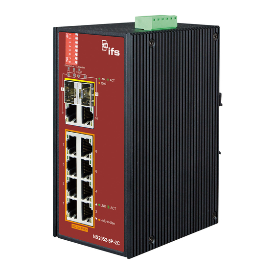
Chapter 1 Package contents The description of the IFS NS2052-8P-2C model is as follows: Industrial 8-port 10/100TX 802.3at PoE+ + 2-port TP/SFP combo Ethernet switch Unless specified, the term “industrial PoE+ switch” mentioned in this user manual refers to the NS2052-8P-2C. -
Page 8: Hardware Introduction
Chapter 2 Hardware introduction Physical dimensions Dimensions (W x D x H): 161 x 107 x 72 mm NS2052-8P-2C Industrial PoE+ Switch User Manual... - Page 9 10/100/1000BASE-T copper, RJ45 twisted-pair: Up to 100 meters. Gigabit SFP slots (port 9 to port 10 TP/SFP combo interfaces) 1000BASE-SX/LX mini-GBIC slot, SFP (Small-form Factor Pluggable) transceiver module: From 550 meters (multi-mode fiber) and to 10/20/30/40/50/70/120 kilometers (single-mode fiber). NS2052-8P-2C Industrial PoE+ Switch User Manual...
- Page 10 Function Green Lit: indicates that the power input 1 has power. Green Lit: indicates that the power input 2 has power. Fault Lit: indicates that either power 1 or power 2 has no power. NS2052-8P-2C Industrial PoE+ Switch User Manual...
- Page 11 1000 Mbps. Off: indicates that the link through that port is not established. Switch upper panel The upper panel of the industrial PoE+ switch consists of one terminal block connector within two DC power inputs. NS2052-8P-2C Industrial PoE+ Switch User Manual...
- Page 12 1. Insert positive/negative DC power wires into contacts 1 and 2 for DC Power 1, or 5 and 6 for DC Power 2. 2. Tighten the wire-clamp screws to prevent the wires from loosening. NS2052-8P-2C Industrial PoE+ Switch User Manual...
-
Page 13: Product Features
2. Alarm relay circuits accept uo to 30 V, max. 3 A currents. Product features Physical port • Eight 10/100BASE-T Fast Ethernet RJ45 copper ports with IEEE 802.3at/af PoE+ injector (port 1 to port 8). NS2052-8P-2C Industrial PoE+ Switch User Manual... -
Page 14: Product Specifications
Hardware DIP switch for “Standard” and “Extend” mode selection; the “Extend” mode features 30 W PoE transmit distance of 250 m at a speed of 10 Mbps. • Automatic address learning and address aging • Supports CSMA/CD protocol Product specifications NS2052-8P-2C Industrial PoE+ Switch User Manual... - Page 15 LNK/ACT (Green) 1000 (Orange) Power Requirement 48 to 56 VDC, 5.5 A (max.), (>51 VDC for PoE+ output recommended) 19 W, 64 BTU (Standby without PoE function) at DC 56 V power input. Power NS2052-8P-2C Industrial PoE+ Switch User Manual...
- Page 16 IEEE 802.3af Power over Ethernet IEEE 802.3at Power over Ethernet Plus Environment Temperature: -40 to 75°C Operating Relative Humidity: 5 to 95% (non-condensing) Temperature: -40 to 85°C Storage Relative Humidity: 5 to 95% (non-condensing) NS2052-8P-2C Industrial PoE+ Switch User Manual...
-
Page 17: Installation
Follow all the DIN-rail installation steps as shown in the example. To install the DIN rails on the industrial PoE+ switch: 1. Screw the DIN-rail onto the industrial PoE+ switch. 2. Carefully slide the DIN-rail into the track. NS2052-8P-2C Industrial PoE+ Switch User Manual... - Page 18 Chapter 3: Installation 3. Ensure that the DIN-rail is tightly attached to the track. To remove the industrial PoE+ switch from the track: Carefully remove the DIN-rail from the track. NS2052-8P-2C Industrial PoE+ Switch User Manual...
-
Page 19: Wall Mount Plate Mounting
5. To remove the wall mount plate, reverse the steps above. Installing the SFP transceiver SFP transceivers are hot-pluggable and hot-swappable. They can be plugged in and removed to/from any SFP port without having to power down the industrial PoE+ switch (see below). NS2052-8P-2C Industrial PoE+ Switch User Manual... - Page 20 4. Check the link mode of the SFP port if the link fails. Note: We recommend the use of Interlogix SFPs on the industrial PoE+switch. If you insert an SFP transceiver that is not supported, the industrial PoE+switch will not recognize it.
- Page 21 Never pull out the module without making use of the lever or the push bolts on the module. Removing the module with force could damage the module and the SFP/SFP+ module slot of the industrial PoE+ switch. NS2052-8P-2C Industrial PoE+ Switch User Manual...
-
Page 22: Troubleshooting
2. If the cord is inserted correctly, replace the power cord. 3. Check that the AC power source is working by connecting a different device in place of the switch. If that device does not work, check the AC power NS2052-8P-2C Industrial PoE+ Switch User Manual... -
Page 23: Appendix A Networking Connection
Interface Cross) detection. This makes it possible to directly connect the industrial PoE+ switch to any Ethernet device without making a crossover cable. The following table and diagram show the standard RJ45 receptacle/ connector and their pin assignments. NS2052-8P-2C Industrial PoE+ Switch User Manual... - Page 24 7 = White / Brown SIDE 2 8 = Brown 8 = Brown Ensure that connected cables are with the same pin assignment and color as the above diagram before deploying the cables into the network. NS2052-8P-2C Industrial PoE+ Switch User Manual...
- Page 25 50/125 μm or 62.5/125 μm 1000BASE-LX (1300 nm) Multi-mode 50/125 μm or 62.5/125 μm Single-mode 9/125 μm Wiring distances Standard Fiber Diameter (micron) Modal Bandwidth Max. Distance (meters) (MHz* km) 1000BASE-SX 62.5 62.5 1000BASE-LX 62.5 5000* NS2052-8P-2C Industrial PoE+ Switch User Manual...
-
Page 26: Appendix B Approved Interlogix Sfp Transceivers
Appendix B Approved Interlogix SFP transceivers The following list of approved Interlogix SFP transceivers is valid as of the time of publication: Optical Optical Receiver Fiber # of Fiber Wave Operating Part # Budget Power Sensitivity Connector Fibers Type Distance... - Page 27 * Note: High Power Optic. There must be a minimum of 5 dB of optical loss to the fiber for proper operation. Note: We recommend the use of Interlogix SFPs on the industrial PoE++ switch. If you insert an SFP transceiver that is not supported, the industrial PoE+ managed switch will not recognize it.