Table of Contents
Advertisement
Quick Links
Advertisement
Table of Contents

Related Manuals for Interlogix IFS NS3550-24T/4S


Summary of Contents for Interlogix IFS NS3550-24T/4S
-
Page 1: Ifs Ns3550-24T/4S User Manual
IFS NS3550-24T/4S User Manual P/N 1072569 • REV 00.05 • ISS 11OCT12... - Page 2 Any similarity to names and addresses of actual businesses or persons is entirely coincidental. Trademarks and The Interlogix name and logo are trademarks of UTC Fire & Security. patents The IFS name and logo are trademarks of UTC Fire & Security.
-
Page 3: Table Of Contents
User’s Manual of NS3550-24T/4S TABLE OF CONTENTS IFS NS3550-24T/4S User Manual.................... 1 1. INTRODUCTION........................18 1.1 Packet Contents ............................18 1.2 Product Description...........................18 1.3 How to Use This Manual..........................20 1.4 Product Features............................21 1.5 Product Specification ..........................24 2. INSTALLATION ........................26 2.1 Hardware Description ..........................26 2.1.1 Switch Front Panel ..............................26... - Page 4 4.2.1 System Information..............................49 4.2.2 IP Configuration..............................50 4.2.3 IPv6 Configuration ...............................51 4.2.4 Users Configuration..........................52 4.2.5 Users Privilege Levels ............................56 4.2.6 NTP Configuration ...............................58 4.2.7 UPnP Configuration.............................58 4.2.8 DHCP Relay ................................60 4.2.9 DHCP Relay Statistics ............................62 4.2.10 CPU Load................................64 4.2.11 System Log................................65 4.2.12 Detailed Log ..............................66 4.2.13 Remote Syslog ..............................67 4.2.14 SMTP Configure ..............................67...
- Page 5 User’s Manual of NS3550-24T/4S 4.4.5 Port Mirroring Configuration ..........................95 4.5 Link Aggregation............................98 4.5.1 Static Aggregation Configuration ........................100 4.5.2 LACP Configuration............................102 4.5.3 LACP System Status ............................103 4.5.4 LACP Port Status...............................105 4.5.5 LACP Port Statistics ............................106 4.6 VLAN................................108 4.6.1 VLAN Overview ..............................108 4.6.2 IEEE 802.1Q VLAN ............................108 4.6.3 VLAN Basic Information ............................
- Page 6 4.8.7 MVR Configuration ............................161 4.8.8 MVR Status ...............................163 4.9 Quality of Service .............................165 4.9.1 Understand QOS ...............................165 4.9.2 QCL Configuration Wizard..........................166 4.9.2.1 Set up Policy Rules ..........................167 4.9.2.2 Set up Typical Network Application Rules ....................168 4.9.2.3 Set up ToS Precedence Mapping ......................171 4.9.2.4 Set up VLAN Tag Priority Mapping ......................172 4.9.3 QoS Control List Configuration..........................173 4.9.3.1 QoS Control Entry Configuration ......................174...
- Page 7 User’s Manual of NS3550-24T/4S 4.12.3 Access Management Statistics ........................237 4.12.4 HTTPs ................................238 4.12.5 SSH .................................238 4.12.6 Port Security Status ............................239 4.12.7 Port Security Detail............................241 4.12.8 DHCP Snooping ..............................242 4.12.9 DHCP Snooping Statistics ..........................244 4.12.10 IP Source Guard Configuration........................245 4.12.11 IP Source Guard Static Table .........................247 4.12.12 ARP Inspection ..............................248 4.12.13 ARP Inspection Static Table...........................249 4.13 Address Table ............................251...
- Page 8 6.1 System Command ............................283 System Configuration ............................283 System Name..............................284 System Contact ..............................285 System Location..............................285 System Timezone..............................286 System Prompt..............................286 System Reboot..............................287 System Restore Default ............................287 System Load ...............................287 System Log .................................288 6.2 IP Command .............................289 IP Configuration..............................289 IP DHCP................................289 IP Setup ................................290 IP Ping.................................290 IP DNS ................................291 IP DNS Proxy ..............................291...
- Page 9 User’s Manual of NS3550-24T/4S MAC Configuration ..............................304 MAC Add ................................304 MAC Delete.................................305 MAC Look up ..............................305 MAC Age Time ..............................306 MAC Learning ..............................306 MAC Dump................................307 MAC Statistics ..............................308 MAC Flush ................................309 6.5 VLAN Configuration Command ......................309 VLAN Configuration.............................309 VLAV PVID ................................310 VLAN Frame Type...............................
- Page 10 Security Switch HTTPs Configuration .........................327 Security Switch HTTPs Mode..........................327 Security Switch HTTPs Redirect .........................328 Security Switch Access Configuration .........................328 Security Switch Access Mode ..........................329 Security Switch Access Add ..........................329 Security Switch Access IPv6 Add ........................330 Security Switch Access Delete ..........................331 Security Switch Access Look up..........................331 Security Switch Access Clear ..........................331 Security Switch Access Statistics ........................332...
- Page 11 User’s Manual of NS3550-24T/4S Security Switch SNMP View Add.........................348 Security Switch SNMP View Delete ........................349 Security Switch SNMP View Look up ........................349 Security Switch SNMP Access Add ........................350 Security Switch SNMP Access Delete.........................350 Security Switch SNMP Access Look up ......................351 Security Network Psec Switch..........................351 Security Network Psec Port..........................352 Security Network Limit Configuration ........................353...
- Page 12 Security Network DHCP Relay Server ........................372 Security Network DHCP Relay Information Mode ....................373 Security Network DHCP Relay Information Policy....................373 Security Network DHCP Relay Statistics......................374 Security Network DHCP Snooping Configuration....................374 Security Network DHCP Snooping Mode ......................375 Security Network DHCP Snooping Port Mode ....................376 Security Network DHCP Snooping Statistics .......................376 Security Network IP Source Guard Configuration ....................377 Security Network IP Source Guard Mode......................378...
- Page 13 User’s Manual of NS3550-24T/4S STP MSTI Map..............................395 STP MSTI Add..............................396 STP Port Configuration ............................396 STP Port Mode..............................396 STP Port Edge ..............................397 STP Port AutoEdge .............................398 STP Port P2P ..............................398 STP Port RestrictedRole .............................399 STP Port RestrictedTcn ............................399 STP Port bpduGuard............................400 STP Port Statistic ..............................400 STP Port Mcheck ..............................401 STP MSTI Port Configuration ..........................401...
- Page 14 LACP Status ................................416 LACP Statistics..............................417 6.12 LLDP Command .............................418 LLDP Configuration .............................418 LLDP Mode .................................418 LLDP Optional TLV..............................419 LLDP Interval...............................420 LLDP Hold ................................420 LLDP Delay .................................421 LLDP Reinit .................................421 LLDP Statistics ..............................422 LLDP Info ................................422 LLDP CDP Aware ..............................423 6.13 LLDPMED Command ..........................423 LLDPMED Configuration .............................423 LLDPMED Civic ..............................424 LLDPMED ECS..............................425...
- Page 15 User’s Manual of NS3550-24T/4S QoS Storm Unicast..............................436 QoS Strom Multicast............................437 QoS Strom Broadcast............................437 QoS DSCP Remarking............................438 QoS DSCP Queue Mapping..........................438 6.15 Mirror Command ............................439 Mirror Configuration.............................439 Mirror Port ................................439 Mirror SID................................440 Mirror Mode.................................440 6.16 Configuration Command ........................442 Configuration Save..............................442 Configuration Load ..............................442 6.17 Firmware Command..........................443 Firmware Load ..............................443 Firmware IPv6 Load ............................443...
- Page 16 Voice VLAN OUI Delete ............................455 Voice VLAN OUI Clear ............................455 Voice VLAN OUI Look up ............................456 Voice VLAN Port Mode............................456 Voice VLAN Security ............................457 6.21 SMTP Command.............................458 SMTP Configuration ............................458 SMTP Mode ................................458 SMTP Server...............................458 SMTP Auth ................................459 SMTP Auth_user ..............................459 SMTP Auth_pass..............................460 SMTP Mailfrom..............................460 SMTP Mailsubject ...............................460...
- Page 17 User’s Manual of NS3550-24T/4S Do_en..................................468 Do_port_alr .................................469 Do_pwr_alr................................469 fault_act................................470 fault_en ................................471 fault_port_alr ...............................471 fault_pwr_alr................................471 7. SWITCH OPERATION ....................... 473 7.1 Address Table ............................473 7.2 Learning ..............................473 7.3 Forwarding & Filtering..........................473 7.4 Store-and-Forward ...........................473 7.5 Auto-Negotiation ............................474 8. TROUBLE SHOOTING...................... 475 APPENDEX A ........................
-
Page 18: Introduction
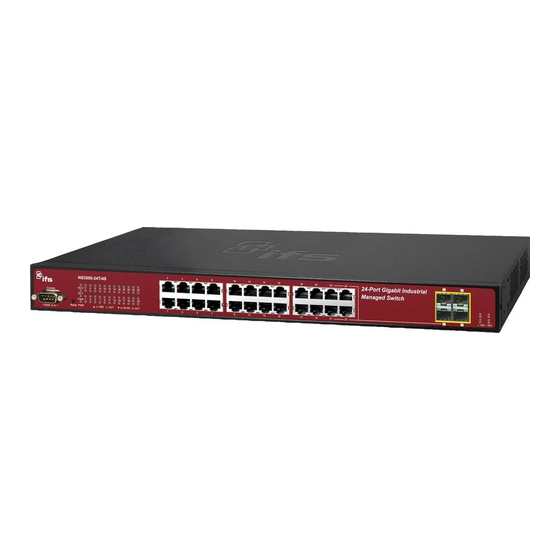
1. INTRODUCTION The IFS NS3550-24T/4S is a 24 ports Gigabit Ethernet Switch with SFP fiber ports and robust layer 2 features. The term “Managed Switch” refers to the NS3550-24T/4S Industrial Switch. 1.1 Packet Contents Open the box of the Managed Switch and carefully unpack it. The box should contain the following items: Check the contents of your package for following parts: ... - Page 19 DC Redundant Power to ensure continuous operation IFS NS3550-24T/4S is equipped with an additional DC 36 ~ 72V power supply unit for redundant power supply installation. Redundant Power Systems are specifically designed to handle the demands of high tech facilities requiring the highest power integrity.
-
Page 20: How To Use This Manual
1.3 How to Use This Manual This User Manual is structured as follows: Section 2, INSTALLATION The section explains the functions of the Switch and how to physically install the Managed Switch. Section 3, SWITCH MANAGEMENT The section contains the information about the software function of the Managed Switch. Section 4, WEB CONFIGURATION The section explains how to manage the Managed Switch by Web interface. -
Page 21: Product Features
User’s Manual of NS3550-24T/4S 1.4 Product Features Physical Port NS3550-24T/4S 24-Port 10/100/1000Base-T Gigabit Ethernet RJ-45 4 100/1000Base-X SFP slots, shared with Port-21 to Port-24 RS-232 DB9 console interface for Switch basic management and setup Industrial Conformance ... - Page 22 ■ Port Mirroring to monitor the incoming or outgoing traffic on a particular port Quality of Service ■ Ingress Shaper and Egress Rate Limit per port bandwidth control ■ 4 priority queues on all switch ports ■ Traffic classification: IEEE 802.1p CoS TOS / DSCP / IP Precedence of IPv4/IPv6 packets IP TCP/UDP port number...
- Page 23 User’s Manual of NS3550-24T/4S SNMP v1, v2c, and v3 switch management SSH / SSL secure access ■ Four RMON groups (history, statistics, alarms, and events) ■ IPv6 IP Address / NTP / DNS management ■ Built-in Trivial File Transfer Protocol (TFTP) client ■...
-
Page 24: Product Specification
1.5 Product Specification Product NS3550-24T/4S Hardware Specification 24 10/ 100/1000Base-T RJ-45 Auto-MDI/MDI-X ports Copper Ports 4 1000Base-SX/LX/BX SFP interfaces, shared with Port 21 to Port 24 SFP/mini-GBIC Slots Compatible with 100Base-FX SFP 1 x RS-232 DB9 serial port (115200, 8, N, 1) Console Port Store-and-Forward Switch Processing Scheme... - Page 25 User’s Manual of NS3550-24T/4S Console, Telnet, Web Browser, SNMPv1, v2c and v3 Basic Management Interfaces SSH, SSL, SNMP v3 Secure Management Interface RFC-1213 MIB-II IF-MIB RFC-1493 Bridge MIB RFC-1643 Ethernet MIB RFC-2863 Interface MIB RFC-2665 Ether-Like MIB RFC-2819 RMON MIB (Group 1) SNMP MIBs RFC-2737 Entity MIB RFC-2618 RADIUS Client MIB...
-
Page 26: Installation
2. INSTALLATION This section describes the hardware features and installation of the Managed Switch on the desktop or rack mount. For easier management and control of the Managed Switch, familiarize yourself with its display indicators, and ports. Front panel illustrations in this chapter display the unit LED indicators. Before connecting any network device to the Managed Switch, please read this chapter completely. -
Page 27: Led Indications
User’s Manual of NS3550-24T/4S Reset Button Pressed and Released Function < 5 sec: System reboot Reboot the Managed Switch Reset the Managed Switch to Factory Default configuration. The Managed Switch will then reboot and load the default settings as below: Default Username: admin 。... -
Page 28: Switch Rear Panel
■ 10/100/1000Base-T interfaces Color Function Iluminates: To indicate the link through that port is successfully established with speed 1000Mbps. 1000 Blink: To indicate that the switch is actively sending or receiving data over that port. Green LNK/ACT Off: If L10/100 NK/ACT LED light-> indicates that the port is operating at 10Mbps or 100Mbps. -
Page 29: Install The Switch
User’s Manual of NS3550-24T/4S 2.2 Install the Switch This section describes how to install your Managed Switch and make connections to the Managed Switch. Please read the following topics and perform the procedures in the order being presented. To install your Managed Switch on a desktop or shelf, simply complete the following steps. -
Page 30: Rack Mounting
Connection to the Managed Switch requires UTP Category 5 network cabling with RJ-45 tips. For more information, please see the Cabling Specification in Appendix A. Supply power to the Managed Switch. Step5: Connect one end of the power cable to the Managed Switch. Connect the power plug of the power cable to a standard wall outlet. -
Page 31: Installing The Sfp Transceiver
User’s Manual of NS3550-24T/4S Figure 2-6 Mounting the Managed Switch on a Rack Step6: Proceeds with the steps 4 and steps 5 of session 2.2.1 Desktop Installation to connect the network cabling and supply power to the Managed Switch. 2.2.3 Installing the SFP transceiver The sections describe how to plug-in an SFP transceiver into an SFP slot. - Page 32 Approved IFS SFP Transceivers IFS Managed Switch supports both Single mode and Multi-mode SFP transceiver. Please refer to below chart, as well as the IFS website for the latest compatible SFP modules: We recommend using IFS SFPs on the Managed Switch. If you insert a SFP transceiver that is not supported, the Managed Switch will not recognize it.
- Page 33 User’s Manual of NS3550-24T/4S Connect the fiber cable Attach the duplex LC connector on the network cable into the SFP transceiver. Connect the other end of the cable to a device – switches with SFP installed, fiber NIC on a workstation or a Media Converter.
-
Page 34: Wiring The Power Input
2.2.4 Wiring the Power Input The 6-contact terminal block connector on the rear panel of NS3550-24T/4S is used for two DC redundant powers inputs. Please follow the steps below to insert the power wire. Insert positive / negative DC power wires into the contacts 1 and 2 for DC POWER 1, or 5 and 6 for DC POWER 2. Figure 2-9 Wiring the Redundant Power Inputs Tighten the wire-clamp screws to prevent the wires from loosening. -
Page 35: Wiring The Digital Input / Output
User’s Manual of NS3550-24T/4S 2.2.5 Wiring the Digital Input / Output The 6-contact terminal block connector on the rear panel of the NS3550-24T/4S is used for Digital Input and Digital Output. Please follow the steps below to insert wire. The NS3550-24T/4S offers two DI and DO groups. 1 and 2 are DI groups, 3 and 4 are DO groups and 5 is GND (ground).The 6 pin is unassigned. - Page 36 Figure 2-13 Wires DI0 and DI1 to Open Detector There are two Digital Output groups for you to be notified of if the NS3550-24T/4S port fails or power fails and issues a high or low signal to external device. The following topology shows how to wire DO0 and DO1. Figure 2-14 Wiring DO0 and DO1 to Open Detector...
- Page 37 User’s Manual of NS3550-24T/4S...
-
Page 38: Switch Management
3. SWITCH MANAGEMENT This chapter explains the methods that you can use to configure management access to the Managed Switch. It describes the types of management applications and the communication and management protocols that deliver data between your management device (workstation or personal computer) and the system. It also contains information about port connection options. -
Page 39: Management Access Overview
User’s Manual of NS3550-24T/4S 3.2 Management Access Overview The Managed Switch gives you the flexibility to access and manage it using any or all of the following methods: An administration console Web browser interface An external SNMP-based network management application The administration console and Web browser interface support are embedded in the Managed Switch software and are available for immediate use. -
Page 40: Direct Access
Figure 3-1 Console Management Diagram Direct Access Direct access to the administration console is achieved by directly connecting a terminal or a PC equipped with a terminal-emulation program (such as HyperTerminal) to the Managed Switch console (serial) port. When using this management method, a straight DB9 RS-232 cable is required to connect the switch to the PC. After making this connection, configure the terminal-emulation program to use the following parameters: The default parameters are: 115200 bps... -
Page 41: Web Management
User’s Manual of NS3550-24T/4S the interface through which the associated action was initiated. A Macintosh or PC attachment can use any terminal-emulation program for connecting to the terminal serial port. A workstation attachment under UNIX can use an emulator such as TIP. 3.4 Web Management The Managed Switch offers management features that allow users to manage the Managed Switch from anywhere on the network through a standard browser such as Microsoft Internet Explorer. -
Page 42: Snmp-Based Network Management
3.5 SNMP-Based Network Management You can use an external SNMP-based application to configure and manage the Managed Switch, such as SNMPc Network Manager, HP Openview Network Node Management (NNM) or What’s Up Gold. This management method requires the SNMP agent on the switch and the SNMP Network Management Station to use the same community string. This management method, in fact, uses two community strings: the get community string and the set community string. -
Page 43: Web Configuration
User’s Manual of NS3550-24T/4S 4. WEB CONFIGURATION This section introduces the configuration and functions of the Web-Based management. About Web-based Management The Managed Switch offers management features that allow users to manage the Managed Switch from anywhere on the network through a standard browser such as Microsoft Internet Explorer. The Web-Based Management supports Internet Explorer 7.0. - Page 44 Logging on the switch Use Internet Explorer 7.0 or above Web browser. Enter the factory-default IP address to access the Web interface. The factory-default IP Address as following: http://192.168.0.100 When the following login screen appears, please enter the default username "admin" with password “admin” (or the username/password you have changed via console) to login the main screen of Managed Switch.
- Page 45 User’s Manual of NS3550-24T/4S Figure 4-1-3 Default Main Page Now, you can use the Web management interface to continue the switch management or manage the Managed Switch by Web interface. The Switch Menu on the left of the web page let you access all the commands and statistics the Managed Switch provides.
-
Page 46: Main Web Page
4.1 Main Web Page The Managed Switch provides a Web-based browser interface for configuring and managing it. This interface allows you to access the Managed Switch using the Web browser of your choice. This chapter describes how to use the Managed Switch’s Web browser interface to configure and manage it. - Page 47 User’s Manual of NS3550-24T/4S Main Menu Using the onboard web agent, you can define system parameters, manage and control the Managed Switch, and all its ports, or monitor network conditions. Via the Web-Management, the administrator can setup the Managed Switch by select the functions those listed in the Main Function.
-
Page 48: System
4.2 System Use the System menu items to display and configure basic administrative details of the Managed Switch. Under System the following topics are provided to configure and view the system information: This section has the following items: The switch system information is provided here. ■... -
Page 49: System Information
User’s Manual of NS3550-24T/4S 4.2.1 System Information The System Info page provides information for the current device information. System Info page helps a switch administrator to identify the hardware MAC address, software version and system uptime. The screen is shown in Figure 4-2-1. -
Page 50: Ip Configuration
System Uptime The period of time the device has been operational. Software Version The software version of the switch. Software Date The software version date of the switch. Buttons Auto-refresh : Check this box to enable an automatic refresh of the page at regular intervals. : Click to refresh the page;... -
Page 51: Ipv6 Configuration
User’s Manual of NS3550-24T/4S Provide the IP address of the router in dotted decimal notation. IP Router VLAN ID Provide the managed VLAN ID. The allowed range is 1 through 4095. DNS Server Provide the IP address of the DNS Server in dotted decimal notation. ... -
Page 52: Users Configuration
IPv4 address. For example, '::192.1.2.34'. Prefix Provide the IPv6 Prefix of this switch. The allowed range is 1 through 128. Router Provide the IPv6 gateway address of this switch. IPv6 address is in 128-bit records represented as eight fields of up to four hexadecimal digits with a colon separate each field (:). - Page 53 User’s Manual of NS3550-24T/4S Figure 4-2-4: User Configuration Interface Screenshot The page includes the following fields: Object Description Display Username of the Managed Switch. Username: Display the access level of the Managed Switch. Access Level: Provide edit current specific user setting. Edit: Provide add new user setting of the Managed Switch, the web screen is shown in Add New User:...
- Page 54 Add / Edit User This page configures a user – add, edit or delete user. Figure 4-2-5: Add New User Configuration Interface Screenshot The page includes the following fields: Object Description Assign Username for the Managed Switch. User Name: Assign the access level of the Managed Switch; the available options are: ...
- Page 55 User’s Manual of NS3550-24T/4S Figure 4-2-6 User Configuration page screenshot After change the default password, if you forget the password. Please press the “Reset” button in the front panel of the Managed Switch over 10 seconds and then release, the current setting includes VLAN, will be lost and the Managed Switch will restore to the default mode.
-
Page 56: Users Privilege Levels
4.2.5 Users Privilege Levels This page provides an overview of the privilege levels. After setup completed, please press “Save” button to take effect. Please login web interface with new user name and password, The screen is shown in Figure 4-2-7. Figure 4-2-7 Privilege Levels Configuration Page Screenshot t The page includes the following fields: Object... - Page 57 User’s Manual of NS3550-24T/4S details: System: Contact, Name, Location, Timezone, Log. Security: Authentication, System Access Management, Port (contains Dot1x port, MAC based and the MAC Address Limit), ACL, HTTPS, SSH, ARP Inspection and IP source guard. IP: Everything except 'ping'. Port: Everything except 'VeriPHY'.
-
Page 58: Ntp Configuration
4.2.6 NTP Configuration Configure NTP on this page. NTP is an acronym for Network Time Protocol, a network protocol for synchronizing the clocks of computer systems. NTP uses UDP (data grams) as transport layer. You can specify NTP Servers and set GMT Time zone. The NTP Configuration screen is shown in Figure 4-2-8. - Page 59 User’s Manual of NS3550-24T/4S UPnP is an acronym for Universal Plug and Play. The goals of UPnP are to allow devices to connect seamlessly and to simplify the implementation of networks in the home (data sharing, communications, and entertainment) and in corporate environments for simplified installation of computer components.
-
Page 60: Dhcp Relay
Buttons : Click to save changes. : Click to undo any changes made locally and revert to previously saved values. Figure 4-2-10 UPnP devices shows on Windows My Network Places 4.2.8 DHCP Relay Configure DHCP Relay on this page. DHCP Relay is used to forward and to transfer DHCP messages between the clients and the server when they are not on the same subnet domain. - Page 61 User’s Manual of NS3550-24T/4S The definition of Circuit ID in the switch is 4 bytes in length and the format is "vlan_id" "module_id" "port_no". The parameter of "vlan_id" is the first two bytes represent the VLAN ID. The parameter of "module_id" is the third byte for the module ID. The parameter of "port_no"...
-
Page 62: Dhcp Relay Statistics
4.2.9 DHCP Relay Statistics This page provides statistics for DHCP relay. The DHCP Relay Statistics screen is shown in Figure 4-2-12. Figure 4-2-12 DHCP Relay Statistics Page Screenshot The page includes the following fields: Server Statistics Object Description Transmit to Server The packets number that relayed from client to server. - Page 63 User’s Manual of NS3550-24T/4S Drop Agent Option The number packets that dropped received packets with relay agent information option. Buttons Auto-refresh : Check this box to enable an automatic refresh of the page at regular intervals. : Click to refresh the page; any changes made locally will be undone. : Clear all statistics.
-
Page 64: Cpu Load
4.2.10 CPU Load This page displays the CPU load, using a SVG graph. The load is measured as averaged over the last 100ms, 1sec and 10 seconds intervals. The last 120 samles are graphed, and the last numbers are displayed as text as well. In order to display the SVG graph, your browser must support the SVG format. -
Page 65: System Log
User’s Manual of NS3550-24T/4S 4.2.11 System Log The switch system log information is provided here. The System Log screen is shown in Figure 4-2-14. Figure 4-2-14 System Log Page Screenshot The page includes the following fields: Object Description ID The ID (>= 1) of the system logging entry. -
Page 66: Detailed Log
: Updates the system log entries, ending at the last available entry ID. 4.2.12 Detailed Log The switch system detailed log information is provided here. The Detailed Log screen is shown in Figure 4-2-15. Figure 4-2-15 Detailed Log Page Screenshot The page includes the following fields: Object Description... -
Page 67: Remote Syslog
User’s Manual of NS3550-24T/4S 4.2.13 Remote Syslog Configure remote syslog on this page. The Remote Syslog screen is shown in Figure 4-2-16. Figure 4-2-16 Remote Syslog Page Screenshot The page includes the following fields: Object Description Mode Indicates the remote syslog mode operation. Possible modes are: Enabled: Enable remote syslog mode operation. - Page 68 Figure 4-2-17 Web Firmware Upgrade Page Screenshot The page includes the following fields: Object Description SMTP Mode Controls whether SMTP is enabled on this switch. SMTP Server Type the SMTP server name or the IP address of the SMTP server. ...
-
Page 69: Web Firmware Upgrade
User’s Manual of NS3550-24T/4S 4.2.15 Web Firmware Upgrade This page facilitates an update of the firmware controlling the switch. The Web Firmware Upgrade screen is shown in Figure 4-2-18. Figure 4-2-18 Web Firmware Upgrade Page Screenshot To open Firmware Upgrade screen perform the folling: Click System ->... -
Page 70: Tftp Firmware Upgrade
4.2.16 TFTP Firmware Upgrade The Firmware Upgrade page provides the functions to allow a user to update the Managed Switch firmware from the TFTP server in the network. Before updating, make sure you have your TFTP server ready and the firmware image is on the TFTP server. -
Page 71: Configuration Backup
User’s Manual of NS3550-24T/4S 4.2.17 Configuration Backup This function allows backup and reload the current configuration of the Managed Switch to the local management station. The Configuration Backup screen is shown in Figure 4-2-21. Figure 4-2-21 Configuration Backup Page Screenshot You can save/view or load the switch configuration. - Page 72 Figure 4-2-22 File Download Screen Chose the file save path in management workstation. Figure 4-2-23 File Save Screen...
-
Page 73: Configuration Upload
User’s Manual of NS3550-24T/4S 4.2.18 Configuration Upload This function allows backup and reload the current configuration of the Managed Switch to the local management station. The Configuration Upload screen is shown in Figure 4-2-24. Figure 4-2-24 Configuration Upload Page Screenshot ... -
Page 74: Digital Input/Output
4.2.19 Digital input/output Digital Input allows the user to manage external devices with customized messages for specific events, and create logs in to system log, syslog, issue SNMP trap or issue an alarm e-mail. Digital Output allows user to monitor the switch port and power , and let system issues a high or low signal to an external device (such as alarm) when the monitor port or power has been failed. -
Page 75: Fault Alarm
User’s Manual of NS3550-24T/4S or Low signal to an external device (such as an alarm). Allows user setting a customize message for Digital Input function alarming. Event Description As Digital Input: Action Allows user to record alarm message to System log, syslog or issues out via SNMP Trap or SMTP. - Page 76 Figure 4-2-27 Windows File Selection Menu Popup The page includes the following fields: Object Description Allows user to enable Fault Alarm function. Enable Allows user to record alarm message to System log, syslog or issues out via Record SNMP Trap or SMTP.
-
Page 77: Factory Default
User’s Manual of NS3550-24T/4S 4.2.21 Factory Default You can reset the configuration of the switch on this page. Only the IP configuration is retained. The new configuration is available immediately, which means that no restart is necessary. The Factory Default screen is shown in Figure 4-2-28. -
Page 78: System Reboot
4.2.22 System Reboot The Reboot page enables the device to be rebooted from a remote location. Once the Reboot button is pressed, the user will have to re-login the WEB interface about 60 seconds later. The System Reboot screen is shown in Figure 4-2-29. -
Page 79: Simple Network Management Protocol
User’s Manual of NS3550-24T/4S 4.3 Simple Network Management Protocol 4.3.1 SNMP Overview The Simple Network Management Protocol (SNMP) is an application layer protocol that facilitates the exchange of management information between network devices. It is part of the Transmission Control Protocol/Internet Protocol (TCP/IP) protocol suite. SNMP enables network administrators to manage network performance, find and solve network problems, and plan for network growth. -
Page 80: Snmp System Configuration
Configure SNMPv3 users table on this page. SNMPv3 Users Configure SNMPv3 groups table on this page. SNMPv3 Groups Configure SNMPv3 views table on this page. SNMPv3 Views Configure SNMPv3 accesses table on this page. SNMPv3 Accesses 4.3.2 SNMP System Configuration Configure SNMP on this page. -
Page 81: Snmp System Information Configuration
User’s Manual of NS3550-24T/4S 4.3.3 SNMP System Information Configuration The switch system information is provided here. The System Information Configuration screen is shown in Figure 4-3-2. Figure 4-3-2 System Information Configuration Page Screenshot The page includes the following fields: Object Description ... - Page 82 Figure 4-3-3 SNMP Trap Configuration Page Screenshot The page includes the following fields: Object Description Indicates the SNMP trap mode operation. Possible modes are: Trap Mode Enabled: Enable SNMP trap mode operation. Disabled: Disable SNMP trap mode operation. Indicates the SNMP trap supported version.
- Page 83 User’s Manual of NS3550-24T/4S : Click to save changes. : Click to undo any changes made locally and revert to previously saved values.
-
Page 84: Snmpv3 Configuration
4.3.5 SNMPv3 Configuration 4.3.5.1 SNMPv3 Communities Configuration Configure SNMPv3 community’s table on this page. The entry index key is Community. The SNMPv3 Communities Configuration screen is shown in Figure 4-3-4. Figure 4-3-4 SNMPv3 Communities Configuration Page Screenshot The page includes the following fields: Object Description ... - Page 85 User’s Manual of NS3550-24T/4S Figure 4-3-5 SNMPv3 Users Configuration Page Screenshot The page includes the following fields: Object Description Check to delete the entry. It will be deleted during the next save. Delete An octet string identifying the engine ID that this entry should belong to. The string Engine ID must contain an even number between 10 and 64 hexadecimal digits, but all-zeros and all-'F's are not allowed.
-
Page 86: Snmpv3 Groups Configuration
4.3.5.3 SNMPv3 Groups Configuration Configure SNMPv3 groups table on this page. The entry index keys are Security Model and Security Name. The SNMPv3 Groups Configuration screen is shown in Figure 4-3-6. Figure 4-3-6 SNMPv3 Groups Configuration Page Screenshot The page includes the following fields: Object Description ... -
Page 87: Snmpv3 Accesses Configuration
User’s Manual of NS3550-24T/4S Figure 4-3-7 SNMPv3 Views Configuration Page Screenshot The page includes the following fields: Object Description Check to delete the entry. It will be deleted during the next save. Delete A string identifying the view name that this entry should belong to. The allowed View Name string length is 1 to 32, and the allowed content is the ASCII characters from 33 to 126. - Page 88 Figure 4-3-8 SNMPv3 Accesses Configuration Page Screenshot The page includes the following fields: Object Description Check to delete the entry. It will be deleted during the next save. Delete A string identifying the group name that this entry should belong to. The allowed Group Name string length is 1 to 32, and the allowed content is the ASCII characters from 33 to 126.
-
Page 89: Port Management
User’s Manual of NS3550-24T/4S 4.4 Port Management Use the Port Menu to display or configure the Managed Switch's ports. This section has the following items: Configures port connection settings Port Configuration Port Statistics Overview Lists Ethernet and RMON port statistics ... - Page 90 The page includes the following fields: Object Description This is the logical port number for this row. Port Description Indicates the per port description. The current link state is displayed graphically. Green indicates the link is up and Link red indicates that it is down.
-
Page 91: Port Statistics Overview
User’s Manual of NS3550-24T/4S 4.4.2 Port Statistics Overview This page provides an overview of general traffic statistics for all switch ports. The ports belong to the currently selected unit, as reflected by the page header. The Port Statistics Overview screen is shown in Figure 4-4-2. -
Page 92: Port Statistics Detail
Filtered The number of received frames filtered by the forwarding process. Buttons : Click to refresh the page immediately. : Clears the counters for all ports. Auto-refresh : Check this box to enable an automatic refresh of the page at regular intervals. 4.4.3 Port Statistics Detail This page provides detailed traffic statistics for a specific switch port. - Page 93 User’s Manual of NS3550-24T/4S The number of received and transmitted (good and bad) multicast packets. Rx and Tx Multicast The number of received and transmitted (good and bad) broadcast packets. Rx and Tx Broadcast Rx and Tx Pause A count of the MAC Control frames received or transmitted on this port that have an opcode indicating a PAUSE operation.
-
Page 94: Sfp Module Information
Auto-refresh : Check this box to enable an automatic refresh of the page at regular intervals. 4.4.4 SFP Module Information You can check the physical or operational status of an SFP module via the SFP Module Information page. This page shows the operational status, such as the transceiver type, speed, and wavelength and supports distance of SFP module on a specific interface. -
Page 95: Port Mirroring Configuration
User’s Manual of NS3550-24T/4S : Click to refresh the page immediately. 4.4.5 Port Mirroring Configuration Configure port Mirroring on this page. This function provide to monitoring network traffic that forwards a copy of each incoming or outgoing packet from one port of a network Switch to another port where the packet can be studied. It enables the manager to keep close track of switch performance and alter it if necessary. - Page 96 Figure 4-4-6 Port Mirror Configuration Page Screenshot...
- Page 97 User’s Manual of NS3550-24T/4S The page includes the following fields: Object Description Port to mirror to Frames from ports that have either source or destination mirroring enabled are mirrored to this port. Disabled option disables mirroring. Switch to mirror to Frames from ports that have either source (rx) or destination (tx) mirroring enabled are mirrored to this switch.
-
Page 98: Link Aggregation
4.5 Link Aggregation Port Aggregation optimizes port usage by linking a group of ports together to form a single Link Aggregated Groups (LAGs). Port Aggregation multiplies the bandwidth between the devices, increases port flexibility, and provides link redundancy. Each LAG is composed of ports of the same speed, set to full-duplex operations. Ports in a LAG, can be of different media types (UTP/Fiber, or different fiber types), provided they operate at the same speed. - Page 99 User’s Manual of NS3550-24T/4S The Link Aggregation Control Protocol (LACP) provides a standardized means for exchanging information between Partner Systems that require high speed redundant links. Link aggregation lets you group up to eight consecutive ports into a single dedicated connection. This feature can expand bandwidth to a device on the network. LACP operation requires full-duplex mode, more detail information refer to the IEEE 802.3ad standard.
-
Page 100: Static Aggregation Configuration
4.5.1 Static Aggregation Configuration This page is used to configure the Aggregation hash mode and the aggregation group. The aggregation hash mode settings are global, whereas the aggregation group relate to the currently selected unit, as reflected by the page header. Hash Code Contributors The Aggeration Mode COnfiguration screen is shown in Figure... - Page 101 User’s Manual of NS3550-24T/4S Figure 4-5-3 Aggregation Group Configuration Page Screenshot The page includes the following fields: .Object Description Indicates the group ID for the settings contained in the same row. Group ID Group ID "Normal" indicates there is no aggregation. Only one group ID is valid per port. ...
-
Page 102: Lacp Configuration
4.5.2 LACP Configuration Link Aggregation Control Protocol (LACP) - LACP LAG negotiate Aggregated Port links with other LACP ports located on a different device. LACP allows switches connected to each other to discover automatically whether any ports are member of the same LAG. -
Page 103: Lacp System Status
User’s Manual of NS3550-24T/4S The page includes the following fields: Object Description The switch port number. Port Controls whether LACP is enabled on this switch port. LACP will form an LACP Enabled aggregation when 2 or more ports are connected to the same partner. LACP can form max 12 LLAGs per switch. - Page 104 The page includes the following fields: Object Description The Aggregation ID associated with this aggregation instance. Aggr ID For LLAG the id is shown as 'isid:aggr-id' and for GLAGs as 'aggr-id' The system ID (MAC address) of the aggregation partner. Partner System ID ...
-
Page 105: Lacp Port Status
User’s Manual of NS3550-24T/4S 4.5.4 LACP Port Status This page provides a status overview for LACP status for all ports. The LACP Port Status screen is shown in Figure 4-5-6. Figure 4-5-6 LACP Port Status Page Screenshot The page includes the following fields: Object Description ... -
Page 106: Lacp Port Statistics
Buttons : Click to refresh the page immediately. Auto-refresh : Check this box to enable an automatic refresh of the page at regular intervals. 4.5.5 LACP Port Statistics This page provides an overview for LACP statistics for all ports. The LACP statistics screen is shown in Figure 4-5-7. - Page 107 User’s Manual of NS3550-24T/4S The page includes the following fields: Object Description The switch port number. Port Shows how many LACP frames have been sent from each port. LACP Transmitted Shows how many LACP frames have been received at each port. LACP Received ...
-
Page 108: Vlan
4.6 VLAN 4.6.1 VLAN Overview A Virtual Local Area Network (VLAN) is a network topology configured according to a logical scheme rather than the physical layout. VLAN can be used to combine any collection of LAN segments into an autonomous user group that appears as a single LAN. - Page 109 User’s Manual of NS3550-24T/4S (such as e-mail), or multicast groups (used for multimedia applications such as videoconferencing). VLANs provide greater network efficiency by reducing broadcast traffic, and allow you to make network changes without having to update IP addresses or IP subnets. VLANs inherently provide a high level of network security since traffic must pass through a configured Layer 3 link to reach a different VLAN.
- Page 110 The tag is inserted into the packet header making the entire packet longer by 4 octets. All of the information originally contained in the packet is retained. 802.1Q Tag User Priority VLAN ID (VID) 3 bits 1 bits 12 bits TPID (Tag Protocol Identifier) TCI (Tag Control Information) 2 bytes...
- Page 111 User’s Manual of NS3550-24T/4S A switch port can have only one PVID, but can have as many VID as the switch has memory in its VLAN table to store them. Because some devices on a network may be tag-unaware, a decision must be made at each port on a tag-aware device before packets are transmitted –...
-
Page 112: Vlan Basic Information
4.6.3 VLAN Basic Information The VLAN Basic Information page displays basic information on the VLAN type supported by the Managed Switch. The VLAN Basic Information screen is shown in Figure 4-6-1. Figure 4-6-1 VLAN Basic Information Page Screenshot The page includes the following fields: Object Description ... -
Page 113: Vlan Port Configuration
User’s Manual of NS3550-24T/4S 4.6.4 VLAN Port Configuration This page is used for configuring the Managed Switch port VLAN. The VLAN per Port Configuration page contains fields for managing ports that are part of a VLAN. The port default VLAN ID (PVID) is configured on the VLAN Port Configuration page. All untagged packets arriving to the device are tagged by the ports PVID. - Page 114 The Managed Switch supports multiple VLAN tags and can therefore be used in MAN applications as a provider bridge, aggregating traffic from numerous independent customer LANs into the MAN (Metro Access Network) space. One of the purposes of the provider bridge is to recognize and use VLAN tags so that the VLANs in the MAN space can be used independent of the customers’...
- Page 115 User’s Manual of NS3550-24T/4S Figure 4-6-2 VLAN Port Configuration Page Screenshot The page includes the following fields: Object Description This is the logical port number for this row. Port PVID Allow assign PVID for selected port. The range for the PVID is 1-4094. The PVID will be inserted into all untagged frames entering the ingress port.
- Page 116 Allow 802.1Q Untagged or Tagged VLAN for selected port. Link Type When adding a VLAN to selected port, it tells the switch whether to keep or remove the tag from a frame on egress. - Untag: outgoing frames without VLAN-Tagged. - Tagged: outgoing frames with VLAN-Tagged.
-
Page 117: Vlan Membership Configuration
User’s Manual of NS3550-24T/4S 4.6.5 VLAN Membership Configuration Adding Static Members to VLANs (VLAN Index) Use the VLAN Static Table to configure port members for the selected VLAN index. The VLAN membership configuration for the selected the switch can be monitored and modified here. Up to 255 VLANs are supported. This page allows for adding and deleting VLANs as well as adding and deleting port members of each VLAN. -
Page 118: Vlan Membership Status For User Static
Buttons : Click to add new VLAN. : Click to save changes. : Click to undo any changes made locally and revert to previously saved values. : Refreshes the displayed table starting from the "VLAN ID" input fields. : Updates the table starting from the first entry in the VLAN Table, i.e. the entry with the lowest VLAN ID. : Updates the table, starting with the entry after the last entry currently displayed. -
Page 119: Vlan Port Status For User Static
User’s Manual of NS3550-24T/4S Buttons : Select VLAN Users from this drop down list. Auto-refresh : Check this box to enable an automatic refresh of the page at regular intervals. : Click to refresh the page immediately. 4.6.7 VLAN Port Status for User Static This page provides VLAN Port Staus. -
Page 120: Port Isolation Configuration
PVID Shows the VLAN identifier for that port. The allowed values are 1 through 4095. The default value is 1. VLAN Aware Show the VLAN Awareness for the port. If VLAN awareness is enabled, the tag is removed from tagged frames received on the port. - Page 121 User’s Manual of NS3550-24T/4S database servers on the inside segment, but are not allowed to communicate with each other For private VLANs to be applied, the switch must first be configured for standard VLAN operation when this is in place. One or more of the configured VLANs can be configured as private VLANs.
-
Page 122: Private Vlan Membership Configuration
shown in Figure 4-6-6. Figure 4-6-6 Port Isolation Configuration Page Screenshot The page includes the following fields: Object Description Port The switch interface. PVLAN Port Type Displays private VLAN port types. - Isolated: A single stand-alone VLAN that contains one promiscuous port and one or more isolated (or host) ports. - Page 123 User’s Manual of NS3550-24T/4S Private VLANs are based on the source port mask, and there are no connections to VLANs. This means that VLAN IDs and Private VLAN IDs can be identical. A port must be a member of both a VLAN and a Private VLAN to be able to forward packets. By default, all ports are VLAN unaware and members of VLAN 1 and Private VLAN 1.
-
Page 124: Vlan Setting Example
Buttons : Click to add new VLAN. : Click to save changes. : Click to undo any changes made locally and revert to previously saved values. 4.6.10 VLAN setting example: - Separate VLAN - 802.1Q VLAN Trunk - Port Isolate 4.6.10.1 Two separate 802.1Q VLAN The diagram shows how the Managed Switch handles Tagged and Untagged traffic flow for two VLANs. - Page 125 User’s Manual of NS3550-24T/4S VLAN Group 1 Port-7~Port-24 VLAN Group 2 Port-1, Port-2 Port-3 VLAN Group 3 Port-4, Port-5 Port-6 Table 4-6-2 VLAN and Port Configuration The scenario described as follow: Untagged packet entering VLAN 2 While [PC-1] transmit an untagged packet enters Port-1, the Managed Switch will tag it with a VLAN Tag=2. [PC-2] and [PC-3] will be received the packet through Port-2 and Port-3.
- Page 126 VLAN 2: Port-1, Port-2 and Port-3 VLAN 3: Port-4, Port-5 and Port-6 VLAN 1: All other ports – Port-7~Port-24 Remove VLAN Member for VLAN 1: Remember to remove the Port 1 – Port 6 from VLAN 1 membership, since the Port 1 – Port 6 had been assigned to VLAN 2 and VLAN 3.
- Page 127 User’s Manual of NS3550-24T/4S Figure 4-6-10 Port 1-Port 6 VLAN Configuration...
-
Page 128: Vlan Trunking Between Two 802.1Q Aware Switch
4.6.10.2 VLAN Trunking between two 802.1Q aware switch The most cases are used for “Uplink” to other switches. VLANs are separated at different switches, but they need to access with other switches within the same VLAN group. The screen is shown in Figure 4-6-11. -
Page 129: Port Isolate
User’s Manual of NS3550-24T/4S VLAN 3: Port-4, Port-5 and Port-6 VLAN 1: All other ports – Port-7~Port-24 About the VLAN ports connect to the hosts, please refer to 4.6.10.1 examples. The following steps will focus on the VLAN Trunk port configuration. Specify Port-8 to be the 802.1Q VLAN Trunk port. - Page 130 4-6-14. This section will show you how to configure the port for the server – that could be accessed by each isolate port. Setup steps Assign Port Mode Set Port-1~Port-4 in Isolate port. Set Port5 and Port-6 to Promiscuous port. The screen is shown in Figure 4-6-15.
- Page 131 User’s Manual of NS3550-24T/4S Figure 4-6-15 The Configuration of Isolate and Promiscuous Port Assign VLAN Member: VLAN 1: Port-1, Port-2, Port-5 and Port-3 VLAN 2: Port-3~Port-6. The screen is shown in Figure 4-6-16. Figure 4-6-16 Private VLAN Port Setting...
-
Page 132: Spanning Tree Protocol
4.7 Spanning Tree Protocol 4.7.1 Theory The Spanning Tree protocol can be used to detect and disable network loops, and to provide backup links between switches, bridges or routers. This allows the switch to interact with other bridging devices in your network to ensure that only one route exists between any two stations on the network, and provide backup links which automatically take over when a primary link goes down. - Page 133 User’s Manual of NS3550-24T/4S The port identifier of the transmitting port The switch sends BPDUs to communicate and construct the spanning-tree topology. All switches connected to the LAN on which the packet is transmitted will receive the BPDU. BPDU does’nt directly forward by the switch, but the receiving switch uses the information in the frame to calculate a BPDU, and, if the topology changes, initiates a BPDU transmission.
- Page 134 Figure 4-7-1 STP Port State Transitions You can modify each port state by using management software. When you enable STP, every port on every switch in the network goes through the blocking state and then transitions through the states of listening and learning at power up. If properly configured, each port stabilizes to the forwarding or blocking state.
- Page 135 User’s Manual of NS3550-24T/4S The following are the user-configurable STP parameters for the switch level: Parameter Description Default Value A combination of the User-set priority and the 32768 + MAC Bridge Identifier(Not user switch’s MAC address. configurable The Bridge Identifier consists of two parts: except by setting priority a 16-bit priority and a 48-bit Ethernet MAC below)
- Page 136 out that your Switch has the lowest Bridge Identifier, it will become the Root Bridge. Forward Delay Timer – The Forward Delay can be from 4 to 30 seconds. This is the time any port on the Switch spends in the listening state while moving from the blocking state to the forwarding state. Observe the following formulas when setting the above parameters: Max.
- Page 137 User’s Manual of NS3550-24T/4S Figure 4-7-2 Before Applying the STA Rules In this example, only the default STP values are used. Figure 4-7-3 After Applying the STA Rules...
-
Page 138: Stp Bridge Configuration
The switch with the lowest Bridge ID (switch C) was elected the root bridge, and the ports were selected to give a high port cost between switches B and C. The two (optional) Gigabit ports (default port cost = 20,000) on switch A are connected to one (optional) Gigabit port on both switch B and C. - Page 139 User’s Manual of NS3550-24T/4S The page includes the following fields: Basic Settings Object Description The STP protocol version setting. Valid values are STP, RSTP and MSTP. Protocol Version The delay used by STP Bridges to transition Root and Designated Ports to Forward Delay Forwarding (used in STP compatible mode).
-
Page 140: Bridge Status
4.7.3 Bridge Status This page provides a status overview for all STP bridge instances. The displayed table contains a row for each STP bridge instance, where the column displays the following information: The STP Bridge Status screen is shown in Figure 4-7-5. - Page 141 User’s Manual of NS3550-24T/4S Figure 4-7-6 STP CIST Port Configuration Page Screenshot The page includes the following fields: Object Description The switch port number of the logical STP port. Port Controls whether RSTP is enabled on this switch port. STP Enabled...
- Page 142 Controls the path cost incurred by the port. The Auto setting will set the path cost Path Cost as appropriate by the physical link speed, using the 802.1D recommended values. Using the Specific setting, a user-defined value can be entered. The path cost is used when establishing the active topology of the network.
-
Page 143: Msti Priorities
User’s Manual of NS3550-24T/4S Half Duplex 2,000,000 Ethernet Full Duplex 1,999,999 Trunk 1,000,000 Half Duplex 200,000 Fast Ethernet Full Duplex 100,000 Trunk 50,000 Full Duplex 10,000 Gigabit Ethernet Trunk 5,000 Table 4-7-2 Recommended STP Path Costs Port Type Link Type IEEE 802.1w-2001 Half Duplex 2,000,000... -
Page 144: Msti Configuration
Priority Controls the bridge priority. Lower numerical values have better priority. The bridge priority plus the MSTI instance number concatenated with the 6-byte MAC address of the switch forms a Bridge Identifier. Buttons : Click to save changes. : Click to undo any changes made locally and revert to previously saved values. 4.7.6 MSTI Configuration This page allows the user to inspect the current STP MSTI bridge instance priority configurations, and possibly change them as well. -
Page 145: Msti Ports Configuration
User’s Manual of NS3550-24T/4S Object Description Configuration Name The name identifiying the VLAN to MSTI mapping. Bridges must share the name and revision (see below), as well as the VLAN-to-MSTI mapping configuration in order to share spanning trees for MSTI's. (Intra-region). The name is at most 32 characters. - Page 146 Select MSTI Select the bridge instance and set more detail configuration. Figure 4-7-10 MST1 MSTI Port Configuration Page Screenshot...
-
Page 147: Port Status
User’s Manual of NS3550-24T/4S The page includes the following fields: MSTx MSTI Port Configuration Object Description Port The switch port number of the corresponding STP CIST (and MSTI) port. Path Cost Controls the path cost incurred by the port. The Auto setting will set the path cost as appropriate by the physical link speed, using the 802.1D recommended values. -
Page 148: Port Statistics
The page includes the following fields: Object Description The switch port number of the logical STP port. Port The current STP port role of the ICST port. The port role can be one of the CIST Role following values: AlternatePort BackupPort RootPort... - Page 149 User’s Manual of NS3550-24T/4S The page includes the following fields: Object Description The switch port number of the logical RSTP port. Port The number of RSTP Configuration BPDU's received/transmitted on the port. RSTP The number of legacy STP Configuration BPDU's received/transmitted on the port.
-
Page 150: Multicast
4.8 Multicast 4.8.1 IGMP Snooping The Internet Group Management Protocol (IGMP) lets host and routers share information about multicast groups memberships. IGMP snooping is a switch feature that monitors the exchange of IGMP messages and copies them to the CPU for feature processing. - Page 151 User’s Manual of NS3550-24T/4S Figure 4-8-1 Multicast Service Figure 4-8-2 Multicast Flooding...
- Page 152 Figure 4-8-3 IGMP Snooping Multicast Stream Control IGMP Versions 1 and 2 Multicast groups allow members to join or leave at any time. IGMP provides the method for members and multicast routers to communicate when joining or leaving a multicast group. IGMP version 1 is defined in RFC 1112.
- Page 153 User’s Manual of NS3550-24T/4S 0x16 Membership Report (version 2) 0x17 Leave a Group (version 2) 0x12 Membership Report (version 1) IGMP packets enable multicast routers to keep track of the membership of multicast groups, on their respective sub networks. The following outlines what is communicated between a multicast router and a multicast group member using IGMP. A host sends an IGMP “report”...
- Page 154 role of querying the LAN for group members. It propagates the service requests on to any doing upstream multicast switch/router to ensure that it will continue to receive the multicast service. Multicast routers use this information, along with a multicast routing protocol such as DVMRP or PIM, to support IP multicasting across the Internet.
-
Page 155: Igmp Snooping Configuration
User’s Manual of NS3550-24T/4S 4.8.2 IGMP Snooping Configuration This page provides IGMP Snooping related configuration. Most of the settings are global, whereas the Router Port configuration is related to the currently selected unit, as reflected by the page header. The IGMP Snooping Configuration screen is shown in Figure 4-8-5. - Page 156 Most of the settings are global, whereas the Router Port configuration is related to the currently selected unit, as reflected by the page header. The IGMP Port Related Configuration screen is shown in Figure 4-8-6. Figure 4-8-6 IGMP Port Related Configuration Page Screenshot The page includes the following fields: Object Description...
-
Page 157: Vlan Configuration
User’s Manual of NS3550-24T/4S Router port. Use this mode when you connect an IGMP multicast server or IP camera which applied with multicast protocol to the port. None: The Managed Switch will not use the specified port as an IGMP Router port. -
Page 158: Port Group Filtering
other devices. Buttons : Refreshes the displayed table starting from the "VLAN" input fields. : Updates the table starting from the first entry in the VLAN Table, i.e. the entry with the lowest VLAN ID. : Updates the table, starting with the entry after the last entry currently displayed. : Click to save changes. -
Page 159: Igmp Snooping Status
User’s Manual of NS3550-24T/4S Object Description Check to delete the entry. It will be deleted during the next save. Delete Port The logical port for the settings. Filtering Group The IP Multicast Group that will be filtered. Buttons : Check to delete the entry. - Page 160 Figure 4-8-9 IGMP Snooping Status Page Screenshot The page includes the following fields: Object Description The VLAN ID of the entry. VLAN ID The present IGMP groups. Max. are 128 groups for each VLAN. Groups The ports that are members of the entry. Port Members ...
-
Page 161: Mvr Configuration
User’s Manual of NS3550-24T/4S Buttons : Click to refresh the page immediately. : Clears all Statistics counters. Auto-refresh : Check this box to enable an automatic refresh of the page at regular intervals. 4.8.7 MVR Configuration In multicast VLAN networks, subscribers to a multicast group can exist in more than one VLAN. If the VLAN boundary restrictions in a network consist of Layer 2 switches Multicast VLAN Registration (MVR) is a protocol for Layer 2 (IP)-networks that enables multicast-traffic from a source VLAN to be shared with subscriber-VLANs. - Page 162 Figure 4-8-10 MVR Configuration Page Screenshot The page includes the following fields: Object Description MVR Mode Enable/Disable the Global MVR.
-
Page 163: Mvr Status
User’s Manual of NS3550-24T/4S VLAN ID Specify the Multicast VLAN ID. Mode Enable MVR on the port. Type Specify the MVR port type on the port. Immediate Leave Enable the fast leave on the port. Buttons : Click to save changes. - Page 164 Buttons : Click to refresh the page immediately. : Clears all Statistics counters. Auto-refresh : Check this box to enable an automatic refresh of the page at regular intervals.
-
Page 165: Quality Of Service
User’s Manual of NS3550-24T/4S 4.9 Quality of Service 4.9.1 Understand QOS Quality of Service (QoS) is an advanced traffic prioritization feature that allows you to establish control over network traffic. QoS enables you to assign various grades of network service to different types of traffic, such as multi-media, video, protocol-specific, time critical, and file-backup traffic. -
Page 166: Qcl Configuration Wizard
Apply a QoS profile to a port(s). 4.9.2 QCL Configuration Wizard This handy wizard helps you set up a QCL quickly. The QCL Configuration Wizard screen is shown in Figure 4-9-1. Figure 4-9-1 Welcome to the QCL Configuration Wizard Page Screenshot The page includes the following fields: Object Description... -
Page 167: Set Up Policy Rules
User’s Manual of NS3550-24T/4S 4.9.2.1 Set up Policy Rules Group ports into several types which according to different QCL policies. The settings relate to the currently selected unit, as reflected by the page header. The screen is shown in Figure 4-9-2. -
Page 168: Set Up Typical Network Application Rules
: Click to start the wizard again. : Click to get more information. : Click to continue the wizard. Once the QCL configuration wizard is finished, the below screen. Buttons : Click to start the wizard again. : Click to get more information. 4.9.2.2 Set up Typical Network Application Rules Set up the specific QCL for different typical network application quality control. - Page 169 User’s Manual of NS3550-24T/4S Figure 4-9-3 Set up Typical Network Application Rules Page Screenshot The page includes the following fields: Object Description Indicates the common servers that apply to the specific QCE . Audio and Video The common servers are: QuickTime 4 Server MSN Messenger Phone Yahoo Messenger Phone...
- Page 170 the frame type that you selected. Figure 4-9-4 Set up Typical Network Application Rules Page 2 Screenshot The page includes the following fields: Object Description Select the QCL ID to which these QCEs apply. QCL ID Select a traffic class of Low, Normal, Medium, or High to apply to the QCE. Traffic Class Buttons : Click to cancel the wizard.
-
Page 171: Set Up Tos Precedence Mapping
User’s Manual of NS3550-24T/4S 4.9.2.3 Set up ToS Precedence Mapping Set up the traffic class mapping to the precedence part of ToS (3 bits) when receiving IPv4/IPv6 packets. The Set up ToS Precedence Mapping screen is shown in Figure 4-9-5. Figure 4-9-5 Set up ToS Precedence Mapping Page Screenshot The page includes the following fields: Object... -
Page 172: Set Up Vlan Tag Priority Mapping
4.9.2.4 Set up VLAN Tag Priority Mapping Set up the traffic class mapping to the User Priority value (3 bits) when receiving VLAN tagged packets. The Set up VLAN Tag Priority Mapping screen is shown in Figure 4-9-6. Figure 4-9-6 Set up VLAN Tag Priority Mapping Page Screenshot The page includes the following fields: Object Description... -
Page 173: Qos Control List Configuration
User’s Manual of NS3550-24T/4S : Click to continue the wizard. The QCL configuration wizard is finished, and the new configuration is ready for use. 4.9.3 QoS Control List Configuration This page lists the QCEs for a given QCL. 4 different QoS classes classified Frameswhich are Low, Normal, Medium, and High. ... -
Page 174: Qos Control Entry Configuration
Type that follows the tag header. VLAN ID: VLAN ID. Only applicable if the frame is VLAN tagged. TCP/UDP Port: IPv4 TCP/UDP source/destination port. DSCP: IPv4 and IPv6 DSCP. ToS: The 3 precedence bit in the ToS byte of the IPv4/IPv6 header (also known as DS field). -
Page 175: Port Qos Configuration
User’s Manual of NS3550-24T/4S The page includes the following fields: Object Description Select the available type for the specific QCE. QCE Type Ethernet Type: Matches the received frame's EtherType against the QCE Key. VLAN ID: Matches the frame's VID against the QCE Key. TCP/UDP Port: Matches the destination port and the source port against the QCE Key. - Page 176 Figure 4-9-9 Port QoS Configuration Page Screenshot The page includes the following fields: Object Description Number of Classes Configure the number of traffic classes as "1", "2", or "4". The default value is "4". The logical port for the settings contained in the same row. Port ...
-
Page 177: Bandwidth Control
User’s Manual of NS3550-24T/4S Select which QCL to use for the port. QCL # Select the default tag priority for this port when adding a Tag to the untagged Tag Priority frames. Select which Queuing mode for this port. Queuing Mode ... - Page 178 Figure 4-9-10 Rate Limit Configuration Page Screenshot The page includes the following fields: Object Description The logical port for the settings contained in the same row. Port Enable or disable the port policer. The default value is "Disabled". Policer Enabled ...
-
Page 179: Storm Control Configuration
User’s Manual of NS3550-24T/4S Shaper Rate Configure the rate for the port shaper. The default value is "500". This value is restricted to 500-1000000 when the "Policer Unit" is "kbps", and it is restricted to 1-1000 when the "Policer Unit" is "Mbps" ... -
Page 180: Qos Statistics
4.9.7 QoS Statistics This page provides statistics for the different queues for all switch ports. The ports belong to the currently selected unit, as reflected by the page header. The QoS Statistics screen is shown in Figure 4-9-12. Figure 4-9-12 QoS Statistics Page Screenshot The page includes the following fields: Object Description... -
Page 181: Dscp Remarking
User’s Manual of NS3550-24T/4S This is the highest priority queue of the 4 QoS queues. High Queue Receive/Transmit The number of received and transmitted packets per port. Buttons : Click to refresh the page immediately. : Clears the counters for all ports. Auto-refresh : Check this box to enable an automatic refresh of the page at regular intervals. - Page 182 Figure 4-9-13 DSCP Remarking Configuration Page Screenshot The page includes the following fields: Object Description The logical port for the settings contained in the same row. Port If the QoS remarking mode is set to enabled, it should be with this DSCP DSCP Remarking remarking/correction function according to RFC2474 on this port.
-
Page 183: Voice Vlan Configuration
User’s Manual of NS3550-24T/4S CS5 = DSCP (40) CS6 = DSCP (48) CS7 = DSCP (56) Expedite Forward = DSCP (46) Buttons : Click to save changes. : Click to undo any changes made locally and revert to previously saved values. 4.9.9 Voice VLAN Configuration The Voice VLAN feature enables the voice traffic forwarding on the Voice VLAN, then the switch can classifying and scheduling to network traffic. - Page 184 Figure 4-9-14 Voice VLAN Configuration Page Screenshot...
-
Page 185: Voice Vlan Oui Table
User’s Manual of NS3550-24T/4S The page includes the following fields: Object Description Mode Indicates the Voice VLAN mode operation. We must disable MSTP feature before we enable Voice VLAN. It can avoid the conflict of ingress filter. Possible modes are: Enabled: Enable Voice VLAN mode operation. -
Page 186: Access Control Lists
Figure 4-9-15 Voice VLAN OUI Table Page Screenshot The page includes the following fields: Object Description Delete Check to delete the entry. It will be deleted during the next save. Telephony OUI An telephony OUI address is a globally unique identifier assigned to a vendor by IEEE. -
Page 187: Access Control List Status
User’s Manual of NS3550-24T/4S access rights. ACL implementations can be quite complex, for example, when the ACEs are prioritized for the various situations. In networking, the ACL refers to a list of service ports or network services that are available on a host or server; each with a list of hosts or servers permitted or denied to use the service. -
Page 188: Access Control List Configuration
CPU Once Forward first packet that matched the specific ACE to CPU. Counter The counter indicates the number of times the ACE was hit by a frame. Conflict Indicates the hardware status of the specific ACE. The specific ACE is not applied to the hardware due to hardware limitations. -
Page 189: Ace Configuration
User’s Manual of NS3550-24T/4S IPv4/Other: The ACE will match IPv4 frames, which are not ICMP/UDP/TCP. Action Indicates the forwarding action of the ACE. Permit: Frames matching the ACE may be forwarded and learned. Deny: Frames matching the ACE are dropped. ... - Page 190 Figure 4-10-3 ACE Configuration Page Screenshot The page includes the following fields: Object Description Select the ingress port for which this ACE applies. Ingress Port Any: The ACE applies to any port. Port n: The ACE applies to this port number, where n is the number of the switch port. Policy n: The ACE applies to this policy number, where n can range from 1 through 8.
- Page 191 User’s Manual of NS3550-24T/4S Object Description (Only displayed when the frame type is Ethernet Type or ARP.) SMAC Filter Specify the source MAC filter for this ACE. Any: No SMAC filter is specified. (SMAC filter status is "don't-care".) Specific: If you want to filter a specific source MAC address with this ACE, choose this value.
- Page 192 Network: Target IP filter is set to Network. Specify the target IP address and target IP mask in the Target IP Address and Target IP Mask fields that appear. Target IP Address When "Host" or "Network" is selected for the target IP filter, you can enter a specific target IP address in dotted decimal notation.
- Page 193 User’s Manual of NS3550-24T/4S zero must not be able to match this entry. Yes: IPv4 frames where the MF bit is set or the FRAG OFFSET field is greater than zero must be able to match this entry. Any: Any value is allowed ("don't-care"). ...
- Page 194 When "Range" is selected for the TCP/UDP source filter, you can enter a specific TCP/UDP Source TCP/UDP source range value. The allowed range is 0 to 65535. A frame that hits Range this ACE matches this TCP/UDP source value. ...
-
Page 195: Acl Ports Configuration
User’s Manual of NS3550-24T/4S 4.10.4 ACL Ports Configuration Configure the ACL parameters (ACE) of each switch port. These parameters will affect frames received on a port unless the frame matches a specific ACE. The settings relate to the currently selected unit, as reflected by the page header. The ACL Ports Configuration screen is shown in Figure 4-10-4. -
Page 196: Acl Rate Limiter Configuration
Select which rate limiter to apply to this port. The allowed values are Disabled or Rate Limiter ID the values 1 through 15. The default value is "Disabled". Select which port frames are copied to. The allowed values are Disabled or a Port Copy specific port number. - Page 197 User’s Manual of NS3550-24T/4S Figure 4-10-5 ACL Rate Limiter Configuration Page Screenshot The page includes the following fields: Object Description The rate limiter ID for the settings contained in the same row. Rate Limiter ID The rate unit is packet per second (pps), configure the rate as 1, 2, 4, 8, 16, 32, Rate 64, 128, 256, 512, 1K, 2K, 4K, 8K, 16K, 32K, 64K, 128K, 256K, 512K, or 1024K.
-
Page 198: Authentication
4.11 Authentication This section is to control the access of the Managed Switch and includes the user access and management control. The Authentication section contains links to the following main topics: IEEE 802.1X Port-Based Network Access Control MAC-Based Authentication ... -
Page 199: Understanding Ieee 802.1X Port-Based Authentication
User’s Manual of NS3550-24T/4S to authenticate. The disadvantage is that MAC addresses can be spoofed by malicious users; equipment whose MAC address is a valid RADIUS user can be used by anyone, and only the MD5-Challenge method is supported. The 802.1X and MAC-Based Authentication configuration consists of two sections, a system- and a port-wide. Overview of User Authentication It is allowed to configure the Managed Switch to authenticate users logging into the system for management access using local or remote authentication methods, such as telnet and Web browser. - Page 200 Figure 4-11-1 Client—the device (workstation) that requests access to the LAN and switch services and responds to requests from the switch. The workstation must be running 802.1X-compliant client software such as that offered in the Microsoft Windows XP operating system. (The client is the supplicant in the IEEE 802.1X specification.) Authentication server—performs the actual authentication of the client.
- Page 201 User’s Manual of NS3550-24T/4S Authentication Initiation and Message Exchange The switch or the client can initiate authentication. If you enable authentication on a port by using the dot1x port-control auto interface configuration command, the switch must initiate authentication when it determines that the port link state transitions from down to up.
-
Page 202: Authentication Configuration
If a client that does not support 802.1X is connected to an unauthorized 802.1X port, the switch requests the client's identity. In this situation, the client does not respond to the request, the port remains in the unauthorized state, and the client is not granted access to the network. -
Page 203: Network Access Server Configuration
User’s Manual of NS3550-24T/4S Authentication Method Authentication Method can be set to one of the following values: None: authentication is disabled and login is not possible. local: use the local user database on the switch for authentication. radius: use a remote RADIUS server for authentication. tacacs+: use a remote TACACS+ server for authentication. - Page 204 Figure 4-11-4 Network Access Server Configuration Page Screenshot...
- Page 205 User’s Manual of NS3550-24T/4S The page includes the following fields: System Configuration Object Description Mode Indicates if NAS is globally enabled or disabled on the switch. If globally disabled, all ports are allowed forwarding of frames. Reauthentication If checked, successfully authenticated supplicants/clients are reauthenticated after the interval specified by the Reauthentication Period.
- Page 206 The "RADIUS-Assigned QoS Enabled" checkbox provides a quick way to globally enable/disable RADIUS-server assigned QoS Class functionality. When checked, the individual ports' ditto setting determines whether RADIUS-assigned QoS Class is enabled for that port. When unchecked, RADIUS-server assigned QoS Class is disabled for all ports. ...
- Page 207 User’s Manual of NS3550-24T/4S In this mode, the switch will send one EAPOL Failure frame when the port link comes up, and any client on the port will be disallowed network access. Port-based 802.1X In the 802.1X-world, the user is called the supplicant, the switch is the authenticator, and the RADIUS server is the authentication server.
- Page 208 In Multi 802.1X it is not possible to use the multicast BPDU MAC address as destination MAC address for EAPOL frames sent from the switch towards the supplicant, since that would cause all supplicants attached to the port to reply to requests sent from the switch.
- Page 209 User’s Manual of NS3550-24T/4S present and valid, the port's Port VLAN ID will be changed to this VLAN ID, the port will be set to be a member of that VLAN ID, and the port will be forced into VLAN unaware mode. Once assigned, all traffic arriving on the port will be classified and switched on the RADIUS-assigned VLAN If (re-)authentication fails or the RADIUS Access-Accept packet no longer carries a VLAN ID or it's invalid, or the supplicant is otherwise no...
- Page 210 VLAN if the "Allow Guest VLAN if EAPOL Seen" is disabled. Port State The current state of the port. It can undertake one of the following values: Globally Disabled: NAS is globally disabled. Link Down: NAS is globally enabled, but there is no link on the port. Authorized: The port is in Force Authorized or a single-supplicant mode and the supplicant is authorized.
-
Page 211: Network Access Overview
User’s Manual of NS3550-24T/4S 4.11.4 Network Access Overview This page provides an overview of the current NAS port states for the selected switch. The Network Access Overview screen is shown in Figure 4-11-5. Figure 4-11-5 Network Access Overview Page Screenshot The page includes the following fields: Object Description... -
Page 212: Network Access Statistics
Port VLAN ID The VLAN ID that NAS has put the port in. The field is blank, if the Port VLAN ID is not overridden by NAS. If the VLAN ID is assigned by the RADIUS server, "(RADIUS-assigned)" is appended to the VLAN ID. - Page 213 User’s Manual of NS3550-24T/4S Port Counters Object Description EAPOL Counters These supplicant frame counters are available for the following administrative states: Force Authorized Force Unauthorized Port-based 802.1X Single 802.1X Multi 802.1X Direction Name IEEE Name Description dot1xAuthEapolFrames The number of valid EAPOL Total frames of any type that have been received by the switch.
- Page 214 Direction Name IEEE Name Description dot1xAuthBackendAcce Access 802.1X-based: ssChallenges Counts the number of times Challenges that the switch receives the first request from the backend server following the first response from the supplicant. Indicates that the backend server has communication with the switch.
- Page 215 User’s Manual of NS3550-24T/4S Last Supplicant/Client Information about the last supplicant/client that attempted to authenticate. This Info information is available for the following administrative states: Port-based 802.1X Single 802.1X Multi 802.1X MAC-based Auth. Name IEEE Name Description dot1xAuthLastEapolF The MAC address of the last supplicant/client. rameSource Address The VLAN ID on which the last frame from the...
-
Page 216: Authentication Server Configuration
Last Authentication Shows the date and time of the last authentication of the client (successful as well as unsuccessful). Buttons Auto-refresh : Check this box to enable an automatic refresh of the page at regular intervals. Click to refresh the page immediately. : This button is available in the following modes: •... - Page 217 User’s Manual of NS3550-24T/4S Figure 4-11-7 Authentication Server Configuration Page Screenshot The page includes the following fields: Port State These setting are common for all of the Authentication Servers. Object Description Timeout The Timeout, which can be set to a number between 3 and 3600 seconds, is the maximum time to wait for a reply from a server.
- Page 218 continue with the next enabled server (if any). RADIUS servers are using the UDP protocol, which is unreliable by design. In order to cope with lost frames, the timeout interval is divided into 3 subintervals of equal length. If a reply is not received within the subinterval, the request is transmitted again.
-
Page 219: Radius Overview
User’s Manual of NS3550-24T/4S Object Description # The TACACS+ Authentication Server number for which the configuration below applies. Enabled Enable the TACACS+ Authentication Server by checking this box. IP Address/Hostname The IP address or hostname of the TACACS+ Authentication Server. IP address is expressed in dotted decimal notation. - Page 220 The page includes the following fields: RADIUS Authentication Servers Object Description # The RADIUS server number. Click to navigate to detailed statistics for this server. IP Address The IP address and UDP port number (in <IP Address>:<UDP Port> notation) of this server.
-
Page 221: Radius Details
User’s Manual of NS3550-24T/4S 4.11.8 RADIUS Details This page provides detailed statistics for a particular RADIUS server. The RADIUS Authentication/Accounting for Server Overview screen is shown in Figure 4-11-9. Figure 4-11-9 RADIUS Authentication/Accounting for Server Overview Page Screenshot The page includes the following fields: RADIUS Authentication Servers The statistics map follows closely to those specified in RFC4668 - RADIUS Authentication Client MIB. - Page 222 server. radiusAuthClientExtA The number of RADIUS Access Rejects ccessRejects Access-Reject packets (valid or invalid) received from the server. radiusAuthClientExtA The number of RADIUS Access ccessChallenges Access-Challenge packets Challenges (valid or invalid) received from the server. radiusAuthClientExt The number of malformed Malformed MalformedAccessRe RADIUS Access-Response...
- Page 223 User’s Manual of NS3550-24T/4S the same server, send to a different server, or give up. A retry to the same server is counted as a retransmit as well as a timeout. A send to a different server is counted as a Request as well as a timeout.
- Page 224 on the accounting port. radiusAccClientExt The number of RADIUS Packets Dropped PacketsDropped packets that were received from the server on the accounting port and dropped for some other reason. radiusAccClientExt The number of RADIUS Requests Requests packets sent to the server. This does not include retransmissions.
-
Page 225: Windows Platform Radius Server Configuration
User’s Manual of NS3550-24T/4S 4.11.9 Windows Platform RADIUS Server Configuration Setup the RADIUS server and assign the client IP address to the Managed switch. In this case, field in the default IP Address of the Managed Switch with 192.168.0.100. And also make sure the shared secret key is as same as the one you had set at the Managed Switch’s 802.1x system configuration –... - Page 226 Figure 4-11-11 Windows Server – add new RADIUS Client Setting Assign the client IP address to the Managed switch Figure 4-11-12 Windows Server RADIUS Server setting...
- Page 227 User’s Manual of NS3550-24T/4S The shared secret key should be as same as the key configured on the Managed Switch. Figure 4-11-13 Windows Server RADIUS Server Setting...
- Page 228 Configure ports attribute of 802.1X, the same as “802.1X Port Configuration”. Figure 4-11-14 802.1x Port Configuration Create user data. The establishment of the user data needs to be created on the Radius Server PC. For example, the Radius Server founded on Win2003 Server, and then: Figure 4-11-15 Windows 2003 AD server Setting Path...
- Page 229 User’s Manual of NS3550-24T/4S Enter ” Active Directory Users and Computers”, create legal user data, the next, right-click a user what you created to enter properties, and what to be noticed: Figure 4-11-16 Add User Properties Screen Figure 4-11-17 Add User Properties Screen...
-
Page 230: Client Configuration
Set the Ports Authenticate Status to “Force Authorized” if the port is connected to the RADIUS server or the port is an uplink port that is connected to another switch. Or once the 802.1X stat to work, the switch might not be able to access the RADIUS server. 4.11.10 802.1X Client Configuration Windows XP supports 802.1X. - Page 231 User’s Manual of NS3550-24T/4S Select “Authentication” tab. Select “Enable network access control using IEEE 802.1X” to enable 802.1x authentication. Select “MD-5 Challenge” from the drop-down list box for EAP type. Figure 4-11-19 Click “OK”. When client has associated with the Managed Switch, a user authentication notice appears in system tray. Click on the notice to continue.
- Page 232 Figure 4-11-20 Windows Client Popup Login Request Message Enter the user name, password and the logon domain that your account belongs. 10. Click “OK” to complete the validation process. Figure 4-11-21...
-
Page 233: Security
User’s Manual of NS3550-24T/4S 4.12 Security This section is to control the access of the Managed Switch and includes the user access and management control. The Security page contains links to the following main topics: Port Limit Control Access Management ... - Page 234 Figure 4-12-1 Port Limit Control Configuration Overview Page Screenshot...
- Page 235 User’s Manual of NS3550-24T/4S The page includes the following fields: System Configuration Object Description Mode Indicates if Limit Control is globally enabled or disabled on the switch. If globally disabled, other modules may still use the underlying functionality, but limit checks and corresponding actions are disabled.
-
Page 236: Access Management
1) Boot from a new masterthe switch, 2) Disable and re-enable Limit Control on the port or the switch, 3) Click the Reopen button. Trap & Shutdown: If Limit + 1 MAC addresses is seen on the port, both the "Trap" and the "Shutdown"... -
Page 237: Access Management Statistics
User’s Manual of NS3550-24T/4S Disabled: Disable access management mode operation. Delete Check to delete the entry. It will be deleted during the next save. Start IP address Indicates the start IP address for the access management entry. End IP address Indicates the end IP address for the access management entry. -
Page 238: Https
Discard Packets The discarded packets number from the interface under access management mode is enabled. Buttons Auto-refresh : Check this box to enable an automatic refresh of the page at regular intervals. : Click to refresh the page immediately. : Clear all statistics. -
Page 239: Port Security Status
User’s Manual of NS3550-24T/4S one chooses to block it, it will be blocked until that user module decides otherwise. The status page is divided into two sections - one with a legend of user modules and one with the actual port status. The SSH Configuration screen is shown in Figure 4-12-5. - Page 240 Figure 4-12-6 Port Security Status Screen Page Screenshot The page includes the following fields: User Module Legend The legend shows all user modules that may request Port Security services. Object Description User Module Name The full name of a module that may request Port Security services.
-
Page 241: Port Security Detail
User’s Manual of NS3550-24T/4S Abbr A one-letter abbreviation of the user module. This is used in the Users column in the port status table. Port Status The table has one row for each port on the selected switch in the switch and a number of columns, which are: Object Description ... -
Page 242: Dhcp Snooping
Figure 4-12-7 Port Security Detail Screen Page Screenshot The page includes the following fields: Object Description MAC Address & VLAN The MAC address and VLAN ID that is seen on this port. If no MAC addresses are learned, a single row stating "No MAC addresses attached" is displayed. ... - Page 243 User’s Manual of NS3550-24T/4S Figure 4-12-8 DHCP Snooping Configuration Screen Page Screenshot The page includes the following fields: Object Description Snooping Mode Indicates the DHCP snooping mode operation. Possible modes are: Enabled: Enable DHCP snooping mode operation. When enabled DHCP snooping, the requested DHCP messages will be forwarded to trusted ports and only allowed reply packets from trusted ports.
-
Page 244: Dhcp Snooping Statistics
Buttons : Click to save changes. Click to undo any changes made locally and revert to previously saved values. 4.12.9 DHCP Snooping Statistics This page provides statistics for DHCP snooping. The statistics only counter packet under DHCP snooping mode is enabled and relay mode is disabled. -
Page 245: Ip Source Guard Configuration
User’s Manual of NS3550-24T/4S The page includes the following fields: Object Description Rx and Tx Discover The number of discover (option 53 with value 1) packets received and transmitted. Rx and Tx Offer The number of offer (option 53 with value 2) packets received and transmitted. ... - Page 246 Figure 4-12-10 IP Source Guard Configuration Screen Page Screenshot The page includes the following fields: Object Description Mode of IP Source Enable the Global IP Source Guard or disable the Global IP Source Guard. All configured ACEs will be lost when the mode is enabled. Guard Configuration ...
-
Page 247: Ip Source Guard Static Table
User’s Manual of NS3550-24T/4S Max Dynamic Clients Specify the maximum number of dynamic clients can be learned on given ports. This value can be 0, 1, 2 and unlimited. If the port mode is enabled and the value of max dynamic client is equal 0, it means only allow the IP packets forwarding that are matched in static entries on the specific port. -
Page 248: Arp Inspection
4.12.12 ARP Inspection ARP Inspection is a secure feature. Several types of attacks can be launched against a host or devices connected to Layer 2 networks by "poisoning" the ARP caches. This feature is used to block such attacks. Only valid ARP requests and responses can go through DUT. -
Page 249: Arp Inspection Static Table
User’s Manual of NS3550-24T/4S Object Description Mode of ARP Enable the Global ARP Inspection or disable the Global ARP Inspection. Inspection Configuration Port Mode Defines the ports on which ARP Inspection is enabled, ARP Inspection is only enabled on this given port when both Global Mode and Port Mode on a given port Configuration are enabled. - Page 250 Click to undo any changes made locally and revert to previously saved values.
-
Page 251: Address Table
User’s Manual of NS3550-24T/4S 4.13 Address Table Switching of frames is based upon the DMAC address contained in the frame. The Managed Switch builds up a table that maps MAC addresses to switch ports for knowing which ports the frames should go to (based upon the DMAC address in the frame). This table contains both static and dynamic entries. -
Page 252: Static Mac Table Configuration
4.13.2 Static MAC Table Configuration The static entries in the MAC table are shown in this table. The static MAC table can contains up to 64 entries. The MAC table is sorted first by VLAN ID and then by MAC address. The Static MAC Table Configuration screen is shown in Figure 4-13-2. - Page 253 User’s Manual of NS3550-24T/4S Figure 4-13-3 MAC Address Table Status Navigating the MAC Table Each page shows up to 999 entries from the MAC table, default being 20, selected through the "entries per page" input field. When first visited, the web page will show the first 20 entries from the beginning of the MAC Table. The first displayed will be the one with the lowest VLAN ID and the lowest MAC address found in the MAC Table.
-
Page 254: Mac Table Learning
The ports that are members of the entry. Port Members Buttons Auto-refresh : Check this box to enable an automatic refresh of the page at regular intervals. : Refreshes the displayed table starting from the "Start from MAC address" and "VLAN" input fields. : Flushes all dynamic entries. -
Page 255: Dynamic Arp Inspection Table
User’s Manual of NS3550-24T/4S Figure 4-13-4 MAC Table Learning Page Screenshot The page includes the following fields: Object Description Learning is done automatically as soon as a frame with unknown SMAC is Auto received. No learning is done. Disable ... - Page 256 Figure 4-13-5 Dynamic ARP Inspection Table Page Screenshot Navigating the ARP Inspection Table Each page shows up to 999 entries from the Dynamic ARP Inspection table, default being 20, selected through the "entries per page" input field. When first visited, the web page will show the first 20 entries from the beginning of the Dynamic ARP Inspection Table.
-
Page 257: Dynamic Ip Source Guard Table
User’s Manual of NS3550-24T/4S 4.13.6 Dynamic IP Source Guard Table Entries in the Dynamic IP Source Guard Table are shown on this page. The Dynamic IP Source Guard Table is sorted first by port, then by VLAN ID, then by IP address, and then by IP mask. The Dynamic IP Source Guard Table screen is shown in Figure 4-13-6. - Page 258 Updates the table starting from the first entry in the MAC Table, i.e. the entry with the lowest VLAN ID and MAC address. : Updates the table, starting with the entry after the last entry currently displayed.
-
Page 259: Lldp
User’s Manual of NS3550-24T/4S 4.14 LLDP 4.14.1 Link Layer Discovery Protocol Link Layer Discovery Protocol (LLDP) is used to discover basic information about neighboring devices on the local broadcast domain. LLDP is a Layer 2 protocol that uses periodic broadcasts to advertise information about the sending device. Advertised information is represented in Type Length Value (TLV) format according to the IEEE 802.1ab standard, and can include details such as device identification, capabilities and configuration settings. - Page 260 Figure 4-14-1 LLDP Configuration Page Screenshot The page includes the following fields: LLDP Parameters Object Description The switch is periodically transmitting LLDP frames to its neighbors for having the Tx Interval network discovery information up-to-date. The interval between each LLDP frame is determined by the Tx Interval value.
- Page 261 User’s Manual of NS3550-24T/4S times. TTL in seconds is based on the following rule: (Transmission Interval * Holdtime Multiplier) ≤ 65536. Therefore, the default TTL is 4*30 = 120 seconds. If some configuration is changed (e.g. the IP address) a new LLDP frame is Tx Delay transmitted, but the time between the LLDP frames will always be at least the value of Tx Delay seconds.
-
Page 262: Lldpmed Configuration
Sys Capa Optional TLV: When checked the "system capability" is included in LLDP information transmitted. The system capabilities identifies the primary function(s) of the system and whether or not these primary functions are enabled. The information advertised by this TLV is described in IEEE 802.1AB. ... - Page 263 User’s Manual of NS3550-24T/4S The page includes the following fields: Fast start repeat count Object Description Rapid startup and Emergency Call Service Location Identification Discovery of Fast start repeat count endpoints is a critically important aspect of VoIP systems in general.In addition, it is best to advertise only those pieces of information which are specifically relevant to particular endpoint types (for example only advertise the voice network policy to permitted voice-capable devices), both in order to conserve the limited LLDPU...
- Page 264 (MLLW). This datum pair is to be used when referencing locations on water/sea/ocean. Civic Address Location IETF Geopriv Civic Address based Location Configuration Information (Civic Address LCI). Object Description Country code The two-letter ISO 3166 country code in capital ASCII letters - Example: DK, DE or US.
- Page 265 User’s Manual of NS3550-24T/4S Emergency Call Service Emergency Call Service (e.g. E911 and others), such as defined by TIA or NENA. Object Description Emergency Call Emergency Call Service ELIN identifier data format is defined to carry the ELIN identifier as used during emergency call setup to a traditional CAMA or ISDN Service trunk-based PSAP.
- Page 266 Application Type Intended use of the application types: Voice - for use by dedicated IP Telephony handsets and other similar appliances supporting interactive voice services. These devices are typically deployed on a separate VLAN for ease of deployment and enhanced security by isolation from data applications.
-
Page 267: Lldp-Med Neighbor
User’s Manual of NS3550-24T/4S Buttons : click to add new policy. : Click to save changes. Click to undo any changes made locally and revert to previously saved values. 4.14.4 LLDP-MED Neighbor This page provides a status overview for all LLDP-MED neighbors. The displayed table contains a row for each port on which an LLDP neighbor is detected. - Page 268 Device (Class III) will also support all aspects of TIA-1057 applicable to both Media Endpoints (Class II) and Generic Endpoints (Class I). LLDP-MED Generic Endpoint (Class I) The LLDP-MED Generic Endpoint (Class I) definition is applicable to all endpoint products that require the base LLDP discovery services defined in TIA-1057, however do not support IP media or act as an end-user communication appliance.
-
Page 269: Neighbor
User’s Manual of NS3550-24T/4S Defined: The network policy is defined. TAG TAG is indicating whether the specified application type is using a tagged or an untagged VLAN. Can be Tagged ot Untagged Untagged: The device is using an untagged frame format and as such does not include a tag header as defined by IEEE 802.1Q-2003. -
Page 270: Port Statistics
System Capabilities System Capabilities describes the neighbor unit's capabilities. The possible capabilities are: 1. Other 2. Repeater 3. Bridge 4. WLAN Access Point 5. Router 6. Telephone 7. DOCSIS cable device 8. Station only 9. Reserved When a capability is enabled, the capability is followed by (+). If the capability is disabled, the capability is followed by (-). - Page 271 User’s Manual of NS3550-24T/4S Figure 4-14-5 LLDP Statistics Page Screenshot The page includes the following fields: Global Counters Object Description Shows the time for when the last entry was last deleted or added. It is also shows Neighbor entries were the time elapsed since last change was detected.
- Page 272 Object Description The port on which LLDP frames are received or transmitted. Local Port The number of LLDP frames transmitted on the port. Tx Frames The number of LLDP frames received on the port. Rx Frames The number of received LLDP frames containing some kind of error.
-
Page 273: Network Diagnostics
User’s Manual of NS3550-24T/4S 4.15 Network Diagnostics This section provide the Physical layer and IP layer network diagnostics tools for troubleshooting. The diagnostic tools are designed for network manager to help them quickly diagnose problems between point to point and better service customers. Use the Diagnastics menu items to display and configure basic administrative details of the Managed Switch. -
Page 274: Ipv6 Ping
ICMP Ping screen is shown in Figure 4-15-1. Figure 4-15-1 ICMP Ping Page Screenshot The page includes the following fields: Object Description The destination IP Address. IP Address The payload size of the ICMP packet. Values range from 8 bytes to 1400 bytes. Ping Size Be sure the target IP Address is within the same network subnet of the switch, or you had setup the correct gateway IP address. -
Page 275: Remote Ip Ping Test
User’s Manual of NS3550-24T/4S Figure 4-15-2 ICMPv6 Ping Page Screenshot The page includes the following fields: Object Description The destination IPv6 Address. IPv6 Address The payload size of the ICMP packet. Values range from 8 bytes to 1400 bytes. Ping Size Buttons : Click to transmit ICMP packets. - Page 276 Figure 4-15-3 Remote IP Ping Test Page Screenshot The page includes the following fields: Object Description Port The logical port for the settings. The destination IP Address. Remote IP Address...
-
Page 277: Cable Diagnostics
User’s Manual of NS3550-24T/4S The payload size of the ICMP packet. Values range from 8 bytes to 1400 bytes. Ping Size Display the ping result. Result 4.15.4 Cable Diagnostics This page is used for running the Cable Diagnostics. Press to run the diagnostics. - Page 278 Figure 4-15-4 VeriPHY Cable Diagnostics Page Screenshot The page includes the following fields: Object Description The port where you are requesting Cable Diagnostics. Port Port: Port number. Cable Status Pair: The status of the cable pair. Length: The length (in meters) of the cable pair. Buttons : Click to run the diagnostics.
-
Page 279: Command Line Interface
User’s Manual of NS3550-24T/4S 5. COMMAND LINE INTERFACE 5.1 Accessing the CLI When accessing the management interface for the switch over a direct connection to the server’s console port, or via a Telnet connection, the switch can be managed by entering command keywords and parameters at the prompt. Using the switch's command-line interface (CLI) is very similar to entering commands on a UNIX system. -
Page 280: Configure Ip Address
For security reason, please change and memorize the new password after this first setup. Only accept command in lowercase letter under console interface. Configure IP address The Managed Switch is shipped with default IP address as following. IP Address: 192.168.0.100 Subnet Mask: 255.255.255.0 To check the current IP address or modify a new IP address for the Switch, please use the procedures as follow: ... - Page 281 User’s Manual of NS3550-24T/4S Subnet Mask: 255.255.255.0 Gateway: 192.168.0.253 VLAN ID: 1 Figure 5-3 Set IP Address Screen Repeat Step 1 to check if the IP address is changed. If the IP address is successfully configured, the Managed Switch will apply the new IP address setting immediately. You can access the Web interface of The Managed Switch through the new IP address.
-
Page 282: Telnet Login
5.2 Telnet Login The Managed Switch also supports telnet for remote management. The switch asks for user name and password for remote login when using telnet, please use “admin” for username & password. -
Page 283: Command Line Mode
User’s Manual of NS3550-24T/4S 6. Command Line Mode The CLI groups all the commands in appropriate modes according to the nature of the command. A sample of the CLI command modes are described below. Each of the command modes supports specific software commands. Command Groups: System System settings and reset options... -
Page 284: System Name
Syntax: System Configuration [all] [<port_list>] Parameters: : Show all switch configuration, default: Show system configuration <port_list>: Port list or 'all', default: All ports Example: To display system information: SWITCH/>System configuration System Contact : System Name :IGSW-24040T System Location : Timezone Offset : 0 CLI Prompt : SWITCH MAC Address... -
Page 285: System Contact
User’s Manual of NS3550-24T/4S System Contact Description: Set or show the system contact. Syntax: System Contact [<contact>] Parameters: <contact>: System contact string. Use 'clear' or "" to clear the string. No blank or space characters are permitted as part of a contact. (only in CLI) Default Setting: empty Example:... -
Page 286: System Timezone
System Timezone Description: Set or show the system timezone offset. Syntax: System Timezone [<offset>] Parameters: <offset>: Time zone offset in minutes (-720 to 720) relative to UTC Default Setting: Example: To set timezone: Switch/>system timezone 0 System Prompt Description: Set the CLI prompt string. Syntax: System Prompt <prompt>... -
Page 287: System Reboot
User’s Manual of NS3550-24T/4S System Reboot Description: Reboot the system. Syntax: System Reboot Example: To reboot device without changing any of the settings: Switch/>system reboot System Restore Default Description: Restore factory default configuration. Syntax: System Restore Default [keep_ip] Parameters: keep_ip: Keep IP configuration, default: Restore full configuration Example: To restore default value but not reset IP address: Switch/>system restore default keep_ip... -
Page 288: System Log
System Log Description: Show or clear the system log. Syntax: System Log [<log_id>] [all|info|warning|error] [clear] Parameters: <log_id>: System log ID or range (default: All entries) : Show all levels (default) : Show informations info warning : Show warnings error : Show errors clear : Clear log Example: To show system log:... -
Page 289: Ip Command
User’s Manual of NS3550-24T/4S 6.2 IP Command IP Configuration Description: Show IP configuration. Syntax: IP Configuration Example: Show IP configuration: Switch/>ip configuration IP Configuration: ================= DHCP Client : Disabled IP Address : 192.168.0.100 IP Mask : 255.255.255.0 IP Router : 192.168.0.1 DNS Server : 0.0.0.0 VLAN ID... -
Page 290: Ip Setup
Disable DHCP sever: SWITCH/>ip dhcp disable IP Setup Description: Set or show the IP setup. Syntax: IP Setup [<ip_addr>] [<ip_mask>] [<ip_router>] [<vid>] Parameters: <ip_addr> : IP address (a.b.c.d), default: Show IP address <ip_mask> : IP subnet mask (a.b.c.d), default: Show IP mask <ip_router>: IP router (a.b.c.d), default: Show IP router : VLAN ID (1-4095), default: Show VLAN ID <vid>... -
Page 291: Ip Dns
User’s Manual of NS3550-24T/4S <ip_addr_string>: IP host address (a.b.c.d) or a host name string <ping_length> : Ping data length (8-1400), excluding MAC, IP and ICMP headers Example: SWITCH/>ip ping 192.168.0.21 PING server 192.168.0.21 60 bytes from 192.168.0.21: icmp_seq=0, time=0ms 60 bytes from 192.168.0.21: icmp_seq=1, time=0ms 60 bytes from 192.168.0.21: icmp_seq=2, time=0ms 60 bytes from 192.168.0.21: icmp_seq=3, time=10ms 60 bytes from 192.168.0.21: icmp_seq=4, time=0ms... -
Page 292: Ipv6 Autocinfig
enable : Enable DNS Proxy disable: Disable DNS Proxy Default Setting: disable Example: Enable DNS proxy function: SWITCH/>ip dns_proxy enable IPv6 AUTOCINFIG Description: Set or show the IPv6 AUTOCONFIG mode. Syntax: IP IPv6 AUTOCONFIG [enable|disable] Parameters: enable : Enable IPv6 AUTOCONFIG mode disable: Disable IPv6 AUTOCONFIG mode Default Setting: disable... -
Page 293: Ipv6 Ping
User’s Manual of NS3550-24T/4S Parameters: <ipv6_addr> : IPv6 address is in 128-bit records represented as eight fields of up to four hexadecimal digits with a colon separates each field (:). For example, four hexadecimal digits with a colon separates each field (:). For example, 'fe80::215:c5ff:fe03:4dc7'. -
Page 294: Ip Ntp Configuration
following legally IPv4 address. For example,'::192.1.2.34'. <ping_length>: Ping data length (8-1400), excluding MAC, IP and ICMP headers Example: SWITCH/>ip ipv6 ping 2001::0002 PING6 server 2001::2 68 bytes from 2001::2: icmp_seq=0, time=0ms 68 bytes from 2001::2: icmp_seq=1, time=0ms 68 bytes from 2001::2: icmp_seq=2, time=0ms 68 bytes from 2001::2: icmp_seq=3, time=0ms 68 bytes from 2001::2: icmp_seq=4, time=0ms Sent 5 packets, received 5 OK, 0 bad... -
Page 295: Ip Ntp Server Add
User’s Manual of NS3550-24T/4S Parameters: : Enable NTP mode enable : Disable NTP mode disable (default: Show NTP mode) Default Setting: disable Example: Enable NTP mode: SWITCH/>ip ntp mode enable IP NTP Server Add Description: Add NTP server entry. Syntax: IP NTP Server Add <server_index>... -
Page 296: Ip Ntp Server Delete
Parameters: <server_index>: The server index (1-5) <server_ipv6> : IPv6 server address. IPv6 address is in 128-bit records represented as eight fields of up to four hexadecimal digits with a colon separate each field (:). For example, 'fe80::215:c5ff:fe03:4dc7'. The symbol '::' is a special syntax that can be used as a shorthand way of representing multiple 16-bit groups of contiguous zeros;... - Page 297 User’s Manual of NS3550-24T/4S...
-
Page 298: Port Management Command
6.3 Port Management Command Port Configuration Description: Show port configuration. Syntax: Port Configuration [<port_list>] [up|down] Parameters: <port_list>: Port list or 'all', default: All ports : Show ports, which are up : Show ports, which are down down (default: Show all ports) Example: Display port1~4 status SWITCH/>port configuration 1-4... -
Page 299: Port Flow Control
User’s Manual of NS3550-24T/4S : 100 Mbps, full duplex 100fdx : 1 Gbps, full duplex 1000fdx : Auto negotiation of speed and duplex auto (default: Show configured and current mode) Default Setting: Auto Example: Set 10Mbps (half duplex) speed for port1 SWITCH/>port mode 1 10hdx Port Flow Control Description:... -
Page 300: Port Maximum Frame
Syntax: Port State [<port_list>] [enable|disable] Parameters: <port_list>: Port list or 'all', default: All ports : Enable port enable : Disable port disable (default: Show administrative mode) Default Setting: Enable Example: Disable port1 SWITCH/>port state 1 disable Port Maximum Frame Description: Set or show the port maximum frame size. -
Page 301: Port Sfp
User’s Manual of NS3550-24T/4S Syntax: Port Power [<port_list>] [enable|disable|actiphy|dynamic] Parameters: <port_list>: Port list or 'all', default: All ports enable : Enable all power control disable: Disable all power control actiphy: Enable ActiPHY power control dynamic: Enable Dynamic power control Default Setting: Enable Example: Disable port power function for port1-4... -
Page 302: Port Excessive
Port Excessive Description: Set or show the port excessive collision mode. Syntax: Port Excessive [<port_list>] [discard|restart] Parameters: <port_list>: Port list or 'all', default: All ports : Discard frame after 16 collisions discard : Restart backoff algorithm after 16 collisions restart (default: Show mode) Default Setting: Discard... -
Page 303: Port Veriphy
User’s Manual of NS3550-24T/4S : Show medium priority statistics medium : Show high priority statistics high (default: Show all port statistics) : Show ports, which are up : Show ports, which are down down (default: Show all ports) Port VeriPHY Description: Run cable diagnostics. -
Page 304: Mac Address Table Command
6.4 MAC Address Table Command MAC Configuration Description: Show MAC address table configuration. Syntax: MAC Configuration [<port_list>] Parameters: <port_list>: Port list or 'all', default: All ports Example: Show Mac address state SWITCH/>mac configuration MAC Configuration: ================== MAC Address : 9c-f6-1a-XX-XX-XX MAC Age Time: 300 Port Learning ---- --------... -
Page 305: Mac Delete
User’s Manual of NS3550-24T/4S Add MAC address table entry. Syntax: MAC Add <mac_addr> <port_list> [<vid>] Parameters: <mac_addr> : MAC address (xx-xx-xx-xx-xx-xx) <port_list>: Port list or 'all' or 'none' : VLAN ID (1-4095), default: 1 <vid> Example: Add Mac address 9c-f6-1a-XX-XX-XX in port1 and vid1 SWITCH/>mac add 9c-f6-1a-XX-XX-XX 1 1 MAC Delete Description:... -
Page 306: Mac Age Time
Parameters: <mac_addr>: MAC address (xx-xx-xx-xx-xx-xx) : VLAN ID (1-4095), default: 1 <vid> Example: Look up state of Mac address 9c-f6-1a-XX-XX-XX SWITCH/>mac lookup 9c-f6-1a-XX-XX-XX MAC Age Time Description: Set or show the MAC address age timer. Syntax: MAC Agetime [<age_time>] Parameters: <age_time>: MAC address age time (0,10-1000000) 0=disable, (default: Show age time) Default Setting:... -
Page 307: Mac Dump
User’s Manual of NS3550-24T/4S auto : Automatic learning disable: Disable learning secure : Secure learning (default: Show learn mode) Default Setting: Auto Example: Set secure learning mode in port1 SWITCH/>mac learning 1 secure MAC Dump Description: Show sorted list of MAC address entries. Syntax: MAC Dump [<mac_max>] [<mac_addr>] [<vid>] Parameters:... -
Page 308: Mac Statistics
Example: Show all of MAC table SWITCH/>mac dump Type VID MAC Address Ports ------ ----------------- ----- Static 9c-f6-1a-XX-XX-XX Static 09c-f6-1a-XX-XX-XX None,CPU Static 33-33-ff-24-04-d1 None,CPU Static 33-33-ff-a8-00-64 None,CPU Dynamic 1 40-61-86-04-18-69 Static ff-ff-ff-ff-ff-ff 1-24,CPU MAC Statistics Description: Show MAC address table statistics. Syntax: MAC Statistics [<port_list>] Parameters:... -
Page 309: Mac Flush
User’s Manual of NS3550-24T/4S Total Dynamic Addresses: 1 Total Static Addresses : 5 MAC Flush Description: Flush all learned entries. Syntax: MAC Flush 6.5 VLAN Configuration Command VLAN Configuration Description: Show VLAN configuration. Syntax: VLAN Configuration [<port_list>] Parameters: <port_list>: Port list or 'all', (default: All ports) Example: Show VLAN status of port1... -
Page 310: Vlav Pvid
Mode : IEEE 802.1Q Port PVID IngrFilter FrameType LinkType Q-in-Q Mode Eth type ---- ---- ---------- ---------- -------- ----------- -------- Disabled UnTag Disable VID Ports ---- ----- 1-24 VLAV PVID Description: Set or show the port VLAN ID. Syntax: VLAN PVID [<port_list>] [<vid>|none]... -
Page 311: Vlan Frame Type
User’s Manual of NS3550-24T/4S Parameters: <port_list>: Port list or 'all', default: All ports <vid>|none : Port VLAN ID (1-4095) or 'none', (default: Show port VLAN ID) Default Setting: Example: Set PVID2 for port20 SWITCH/>vlan pvid 20 2 VLAN Frame Type Description: Set or show the port VLAN frame type. -
Page 312: Vlan Mode
Syntax: VLAN IngressFilter [<port_list>] [enable|disable] Parameters: <port_list>: Port list or 'all', default: All ports : Enable VLAN ingress filtering enable : Disable VLAN ingress filtering disable (default: Show VLAN ingress filtering) Default Setting: Disable Example: Enable VLAN ingress filtering for port20 SWITCH/>vlan ingressfilter 20 enable VLAN Mode Description:... -
Page 313: Vlan Link Type
User’s Manual of NS3550-24T/4S VLAN Link Type Description: Set or show the port VLAN link type. Syntax: VLAN LinkType [<port_list>] [untagged|tagged] Parameters: <port_list>: Port list or 'all', default: All ports untagged : VLAN Link Type Tagged : VLAN Link Type Untagged tagged (default: Show VLAN link type) Default Setting:... -
Page 314: Vlan Ethernet Type
SWITCH/>vlan qinq 2 man VLAN Ethernet Type Description: Set or show out layer VLAN tag ether type in Q-in-Q VLAN mode. Syntax: VLAN Ethtype [<port_list>] [man|dot1q] Parameters: <port_list>: Port list or 'all', default: All ports : Set out layer VLAN tag ether type : MAN : Set out layer VLAN tag ether type : 802.1Q dot1q (default: Show VLAN out layer VLAN tag ether type) -
Page 315: Vlan Delete
User’s Manual of NS3550-24T/4S Example: Add port17 to port24 in VLAN10 SWITCH/>vlan add 10 17-24 VLAN Delete Description: Delete VLAN entry. Syntax: VLAN Delete <vid> Parameters: <vid>: VLAN ID (1-4095) Example: Delete port17 to port24 in VLAN10 SWITCH/>vlan delete 10 VLAN Look up Description: Look up VLAN entry. -
Page 316: Vlan Status
Example: Show VLAN status SWITCH/>vlan lookup VID Ports ---- ----- 1-24 200 None VLAN Status Description: VLAN Port Configuration Status. Syntax: VLAN Status [<port_list>] [combined|static|nas|mvr|voice_vlan|mstp|all|conflicts] Parameters: <port_list>: Port list or 'all', default: All ports : combined VLAN Users configuration combined : static port configuration static : NAS port configuration... -
Page 317: Private Vlan Configuration Command
User’s Manual of NS3550-24T/4S 6.6 Private VLAN Configuration Command PVLAN Configuration Description: Show Private VLAN configuration. Syntax: PVLAN Configuration [<port_list>]... -
Page 318: Pvlan Add
Parameters: <port_list>: Port list or 'all', default: All ports Example: Show private VLAN configuration SWITCH/> pvlan configuration Private VLAN Configuration: =========================== Port Isolation ---- --------- Disabled Disabled Disabled Disabled Disabled Disabled Disabled Disabled Disabled Disabled Disabled Disabled Disabled Disabled Disabled Disabled Disabled Disabled... -
Page 319: Pvlan Delete
User’s Manual of NS3550-24T/4S Example: Add port17 to port24 in PVLAN10 SWITCH/>pvlan add 10 17-24 PVLAN Delete Description: Delete Private VLAN entry. Syntax: PVLAN Delete <pvlan_id>... -
Page 320: Pvlan Look Up
Parameters: <pvlan_id> : Private VLAN ID Example: Delete PVLAN10 SWITCH/>pvlan delete 10 PVLAN Look up Description: Look up Private VLAN entry. Syntax: PVLAN Look up [<pvlan_id>] Parameters: <pvlan_id> : Private VLAN ID Example: Look up PVLAN SWITCH/> lookup PVLAN ID Ports -------- ----- 1-24 PVLAN Isolate... -
Page 321: Security Command
User’s Manual of NS3550-24T/4S Default Setting: Promiscous Example: Enable isolate for port10 SWITCH/>pvlan isolate 10 enable 6.7 Security Command Security Switch User Configuration Description:... -
Page 322: Security Switch User Add
Show users configuration. Syntax: Security Switch Users Configuration Default Setting: User Name Privilege admin guest Example: Enable isolate for port10 SWITCH/>security switch user configuration Users Configuration: ==================== User Name Privilege Level -------------------------------- ---------------- admin guest Security Switch User Add Description: Add or modify users entry. -
Page 323: Security Switch Privilege Level Configuration
User’s Manual of NS3550-24T/4S Delete users entry. Syntax: Security Switch Users Delete <user_name> Parameters: <user_name>: A string identifying the user name that this entry should belong to Example: Delete test account. SWITCH/>security switch users delete user Security Switch Privilege Level Configuration Description: Show privilege configuration. -
Page 324: Security Switch Privilege Level Group
System 5 10 1 10 UPnP 5 10 5 10 VLANs 5 10 5 10 Voice_VLAN 5 10 5 10 Security Switch Privilege Level Group Description: Configure a privilege level group. Syntax: Security Switch Privilege Level Group <group_name> [<cro>] [<crw>] [<sro>] [<srw>] Parameters: <group_name>: Privilege group name, default: Show all group privilege level : Configuration read-only privilege level (1-(15)) -
Page 325: Security Switch Auth Method
User’s Manual of NS3550-24T/4S Show Auth configuration. Syntax: Security Switch Auth Configuration Default Setting: Authentication Method: local Fallback: disable Example: Show authentication configuration. SWITCH/>security switch auth configuration Auth Configuration: =================== Client Authentication Method Local Authentication Fallback ------- ---------------------- ----------------------------- console local Disabled telnet local... -
Page 326: Security Switch Ssh Configuration
(default: Show backup client authentication configuration) Default Setting: Authentication Method: local Fallback: disable Example: Use RADIUS authentication method for telnet. SWITCH/>security switch auth method telnet radius enable Security Switch SSH Configuration Description: Show SSH configuration. Syntax: Security Switch SSH Configuration Example: Show SSH configuration. -
Page 327: Security Switch Https Configuration
User’s Manual of NS3550-24T/4S Default Setting: disable Example: Enable SSH function. SWITCH/>security switch ssh mode enable Security Switch HTTPs Configuration Description: Show HTTPS configuration. Syntax: Security Switch HTTPS Configuration Default Setting: disable Example: Show HTTPs configuration. SWITCH/>security switch https configuration HTTPS Configuration: ==================== HTTPS Mode... -
Page 328: Security Switch Https Redirect
(default: Show HTTPs mode) Default Setting: disable Example: Enable HTTPs function. SWITCH/>security switch https mode enable Security Switch HTTPs Redirect Description: Set or show HTTPS redirect mode. Automatic redirect web browser to HTTPS during HTTPS mode enabled. Syntax: Security Switch HTTPS Redirect [enable|disable] Parameters: enable : Enable HTTPs redirect disable: Disable HTTPs redirect... -
Page 329: Security Switch Access Mode
User’s Manual of NS3550-24T/4S Example: Show access management configuration. SWITCH/>security switch access configuration Access Mgmt Configuration: ========================== System Access Mode : Disabled System Access number of entries: 0 Security Switch Access Mode Description: Set or show the access management mode. Syntax: Security Switch Access Mode [enable|disable] Parameters:... -
Page 330: Security Switch Access Ipv6 Add
: entry index (1-16) <access_id> <start_ip_addr>: Start IP address (a.b.c.d) <end_ip_addr> : End IP address (a.b.c.d) : WEB/HTTPS interface : SNMP interface snmp : TELNET/SSH interface telnet (default: Show configured and current mode) Example: Add access management list from 192.168.0.1 to 192.168.0.200 via web interface. SWITCH/>security switch access add 1 192.168.0.1 192.168.0.200 web Security Switch Access IPv6 Add Description:... -
Page 331: Security Switch Access Delete
User’s Manual of NS3550-24T/4S Add access management list from 2001::0001 to 2001::0100 via web interface. SWITCH/> security switch access add 2001::0001 2001::0100 web Security Switch Access Delete Description: Delete access management entry. Syntax: Security Switch Access Delete <access_id Parameters: <access_id>: entry index (1-16) Example: Delete access management ID 1 SWITCH/>security switch access delete 1... -
Page 332: Security Switch Access Statistics
Syntax: Security Switch Access Clear Example: Clear to access management entry. SWITCH/>security switch access clear Security Switch Access Statistics Description: Show up or clear to access management statistics. Syntax: Security Switch Access Statistics [clear] Parameters: clear: Clear access management statistics Default Setting: disable Example:... - Page 333 User’s Manual of NS3550-24T/4S SWITCH/>security switch snmp configuration SNMP Configuration: =================== SNMP Mode : Enabled SNMP Version : 2c Read Community : public Write Community : private Trap Mode : Disabled Trap Version Trap Community : public Trap Destination Trap IPv6 Destination : :: Trap Authentication Failure : Enabled Trap Link-up and Link-down...
-
Page 334: Security Switch Snmp Mode
Security Switch SNMP Mode Description: Set or show the SNMP mode. Syntax: Security Switch SNMP Mode [enable|disable] Parameters: enable : Enable SNMP disable: Disable SNMP (default: Show SNMP mode) Default Setting: enable Example: Disable SNMP mode. SWITCH/>security switch snmp mode disable Security Switch SNMP Version Description: Set or show the SNMP protocol version. -
Page 335: Security Switch Snmp Read Community
User’s Manual of NS3550-24T/4S SWITCH/>security switch snmp version 3 Security Switch SNMP Read Community Description: Set or show the community string for SNMP read access. Syntax: Security Switch SNMP Read Community [<community>]... -
Page 336: Security Switch Snmp Write Community
Parameters: <community>: Community string. Use 'clear' or "" to clear the string (default: Show SNMP read community) Default Setting: public Example: Set to SNMP read community private. SWITCH/>security switch snmp read community private Security Switch SNMP Write Community Description: Set or show the community string for SNMP write access. Syntax: Security Switch SNMP Write Community [<community>] Parameters:... -
Page 337: Security Switch Snmp Trap Version
User’s Manual of NS3550-24T/4S Parameters: enable : Enable SNMP traps disable: Disable SNMP traps (default: Show SNMP trap mode) Default Setting: disable Example: Enable SNMP trap mode. SWITCH/>security switch snmp trap mode enable Security Switch SNMP Trap Version Description: Set or show the SNMP trap protocol version. Syntax: Security Switch SNMP Trap Version [1|2c|3] Parameters:... -
Page 338: Security Switch Snmp Trap Destination
Syntax: Security Switch SNMP Trap Community [<community>] Parameters: <community>: Community string. Use 'clear' or "" to clear the string (default: Show SNMP trap community) Default Setting: public Example: Set private value for SNMP trap community. SWITCH/>security switch snmp trap community private Security Switch SNMP Trap Destination Description: Set or Show the SNMP trap destination address. -
Page 339: Security Switch Snmp Trap Authentication Failure
User’s Manual of NS3550-24T/4S Parameters: <ipv6_addr>: IPv6 address is in 128-bit records represented as eight fields of up to four hexadecimal digits with a colon separate each field (:). For example, four hexadecimal digits with a colon separate each field (:). For example, fe80::215:c5ff:fe03:4dc7'. -
Page 340: Security Switch Snmp Trap Inform Mode
Syntax: Security Switch SNMP Trap Link-up [enable|disable] Parameters: enable : Enable SNMP trap link-up and link-down disable: Disable SNMP trap link-up and link-down (default: Show SNMP trap link-up and link-down mode) Default Setting: enable Example: Disable SNMP trap link-up SWITCH/>security switch snmp trap link-up disable Security Switch SNMP Trap Inform Mode Description: Set or show the SNMP trap inform mode. -
Page 341: Security Switch Snmp Trap Inform Timeout
User’s Manual of NS3550-24T/4S Security Switch SNMP Trap Inform Timeout Description: Set or shows the SNMP trap inform timeout (usecs). Syntax: Security Switch SNMP Trap Inform Timeout [<timeout>] Parameters: <timeout>: SNMP trap inform timeout (0-2147 seconds) (default: Show SNMP trap inform timeout) Default Setting: Example: Set SNMP trap inform timeout in 20sec. -
Page 342: Security Switch Snmp Trap Probe Security Engine Id
Security Switch SNMP Trap Probe Security Engine ID Description: Show SNMP trap security engine ID probe mode. Syntax: Security Switch SNMP Trap Probe Security Engine ID [enable|disable] Parameters: enable : Enable SNMP trap security engine ID probe disable: Disable SNMP trap security engine ID probe (default: Show SNMP trap security engine ID probe mode) Default Setting: enable... -
Page 343: Security Switch Snmp Trap Security Name
User’s Manual of NS3550-24T/4S Security Switch SNMP Trap Security Name Description: Set or show SNMP trap security name. Syntax: Security Switch SNMP Trap Security Name [<security_name>] Parameters: <security_name>: A string representing the security name for a principal (default: Show SNMP trap security name) Example: Set the SNMP trap security name SWITCH/>security switch snmp trap security name 12345678... -
Page 344: Security Switch Snmp Community Delete
Add or modify SNMPv3 community entry. The entry index key is <community>. Syntax: Security Switch SNMP Community Add <community> [<ip_addr>] [<ip_mask>] Parameters: <community>: Community string <ip_addr> : IP address (a.b.c.d), default: Show IP address <ip_mask> : IP subnet mask (a.b.c.d), default: Show IP mask Example: Add SNMPv3 community entry. -
Page 345: Security Switch Snmp User Add
User’s Manual of NS3550-24T/4S Parameters: <index>: entry index (1-64) Example: Look up SNMPv3 community entry SWITCH/>security switch snmp community lookup Idx Community Source IP Source Mask --- -------------------------------- --------------- --------------- 1 public 192.168.0.20 255.255.255.0 2 private 0.0.0.0 0.0.0.0 Number of entries: 2 Security Switch SNMP User Add Description: Add SNMPv3 user entry. -
Page 346: Security Switch Snmp User Changekey
Syntax: Security Switch SNMP User Delete <index> Parameters: <index>: entry index (1-64) Example: Delete SNMPv3 user entry SWITCH/>security switch snmp user delete 1 Security Switch SNMP User Changekey Description: Change SNMPv3 user password. Syntax: Security Switch SNMP User Changekey <engineid> <user_name> <auth_password> [<priv_password>] Parameters: : Engine ID, the format may not be all zeros or all 'ff'H and is restricted to 5 - 32 octet string <engineid>... -
Page 347: Security Switch Snmp Group Add
User’s Manual of NS3550-24T/4S Example: Look up SNMPv3 user entry SWITCH/>security switch snmp user lookup Idx Engine ID User Name Level Auth Priv --- --------- -------------------------------- -------------- ---- ---- 1 Remote admin_snmpv3 Auth, Priv MD5 DES Number of entries: 1 Security Switch SNMP Group Add Description: Add or modify SNMPv3 group entry. -
Page 348: Security Switch Snmp Group Look Up
Example: Delete SNMPv3 group entry SWITCH/>security switch snmp group delete 1 Security Switch SNMP Group Look up Description: Look up SNMPv3 group entry. Syntax: Security Switch SNMP Group Look up [<index>] Parameters: <index>: entry index (1-64) Example: Look up SNMPv3 group entry SWITCH/>security switch snmp group lookup Idx Model Security Name Group Name... -
Page 349: Security Switch Snmp View Delete
User’s Manual of NS3550-24T/4S Example: Add SNMPv3 view entry SWITCH/>security switch snmp view add snmpv3_view include .1 Security Switch SNMP View Delete Description: Delete SNMPv3 view entry. Syntax: Security Switch SNMP View Delete <index> Parameters: <index>: entry index (1-64) Example: Delete SNMPv3 view entry SWITCH/>security switch snmp view delete 3 Security Switch SNMP View Look up... -
Page 350: Security Switch Snmp Access Add
Security Switch SNMP Access Add Description: Add or modify SNMPv3 access entry. The entry index key are <group_name>, <security_model> and <security_level>. Syntax: Security Switch SNMP Access Add <group_name> <security_model> <security_level> [<read_view_name>] [<write_view_name>] Parameters: : A string identifying the group name that this entry should belong to <group_name>... -
Page 351: Security Switch Snmp Access Look Up
User’s Manual of NS3550-24T/4S Example: Delete SNMPv3 access entry SWITCH/>security switch snmp access delete 3 Security Switch SNMP Access Look up Description: Look up SNMPv3 access entry. Syntax: Security Switch SNMP Access Look up [<index>] Parameters: <index>: entry index (1-64) Example: Look up SNMPv3 access entry SWITCH/>security switch snmp access lookup... -
Page 352: Security Network Psec Port
Example: Show port security status. SWITCH/>security network psec switch Users: L = Limit Control 8 = 802.1X D = DHCP Snooping V = Voice VLAN Port Users State MAC Cnt ---- ----- ------------- ------- ---- No users ---- No users ---- No users ----... -
Page 353: Security Network Limit Configuration
User’s Manual of NS3550-24T/4S MAC Address VID State Added Age/Hold Time ----------------- ---- ---------- ------------------------- ------------- <none> Security Network Limit Configuration Description: Show Limit Control configuration. Syntax: Security Network Limit Configuration [<port_list>] Parameters: <port_list>: Port list or 'all', default: All ports Example: Show Limit Control configuration. -
Page 354: Security Network Limit Mode
Security Network Limit Mode Description: Set or show global enabledness. Syntax: Security Network Limit Mode [enable|disable] Parameters: enable : Globally enable port security disable : Globally disable port security (default: Show current global enabledness of port security limit control) Default Setting: disable Example: Enable the limit mode... -
Page 355: Security Network Limit Agetime
User’s Manual of NS3550-24T/4S Syntax: Security Network Limit Aging [enable|disable] Parameters: enable : Enable aging disable : Disable aging (default: Show current enabledness of aging) Default Setting: disable Example: Enable limit aging SWITCH/>security network limit aging enable Security Network Limit Agetime Description: Time in second between check for activity on learned MAC addresses. -
Page 356: Security Network Limit Limit
Syntax: Security Network Limit Port [<port_list>] [enable|disable] Parameters: <port_list>: Port list or 'all', default: All ports enable : Enable port security on this port disable : Disable port security on this port (default: Show current port enabledness of port security limit control) Default Setting: disable Example:... -
Page 357: Security Network Limit Action
User’s Manual of NS3550-24T/4S Security Network Limit Action Description: Set or show the action involved with exceeding the limit. Syntax: Security Network Limit Action [<port_list>] [none|trap|shut|trap_shut] Parameters: : Port list or 'all', default: All ports <port_list> none|trap|shut|trap_shut: Action to be taken in case the number of MAC addresses exceeds the limit : Don't do anything none : Send an SNMP trap... -
Page 358: Security Network Nas Configuration
Security Network NAS Configuration Description: Show 802.1X configuration. Syntax: Security Network NAS Configuration [<port_list>] Parameters: <port_list>: Port list or 'all', default: All ports Example: Show 802.1X configuration of port 1 SWITCH/>security network nas configuration 1 802.1X Configuration: ===================== Mode : Disabled Reauth. -
Page 359: Security Network Nas State
User’s Manual of NS3550-24T/4S Default Setting: disable Example: Enable IEEE802.1X function SWITCH/>security network nas mode enable Security Network NAS State Description: Set or show the port security state. Syntax: Security Network NAS State [<port_list>] [auto|authorized|unauthorized|single|multi|macbased] Parameters: <port_list>: Port list or 'all', default: All ports : Port-based 802.1X Authentication auto authorized : Port access is allowed... -
Page 360: Security Network Nas Reauthperiod
Set or show Reauthentication enabledness. Syntax: Security Network NAS Reauthentication [enable|disable] Parameters: enable : Enable reauthentication disable: Disable reauthentication (default: Show current reauthentication mode) Default Setting: disable Example: Enable reauthentication function. SWITCH/>security network nas reauthentication enable Security Network NAS ReauthPeriod Description: Set or show the period between reauthentications. -
Page 361: Security Network Nas Eapoltimeout
User’s Manual of NS3550-24T/4S Security Network NAS EapolTimeout Description: Set or show the time between EAPOL retransmissions. Syntax: Security Network NAS EapolTimeout [<eapol_timeout>] Parameters: <eapol_timeout>: Time between EAPOL retransmissions (1-65535 seconds) (default: Show current EAPOL retransmission timeout) Default Setting: Example: Set the time between EAPOL retransmissions for 100sec. -
Page 362: Security Network Nas Holdtime
Security Network NAS Holdtime Description: Time in seconds before a MAC-address that failed authentication gets a new authentication chance. Syntax: Security Network NAS Holdtime [<hold_time>] Parameters: <hold_time>: Hold time before MAC addresses that failed authentication expire (default: Show current hold time) Default Setting: Example: Set NAS hold time in 100sec... -
Page 363: Security Network Nas Radius_Vlan
User’s Manual of NS3550-24T/4S Example: Enable NAS RADIUS QoS SWITCH/>security network nas radius_qos enable Security Network NAS RADIUS_VLAN Description: Set or show either global enabledness (use the global keyword) or per-port enabledness of RADIUS-assigned VLAN. Syntax: Security Network NAS RADIUS_VLAN [global|<port_list>] [enable|disable] Parameters: : Select the global RADIUS-assigned VLAN setting global... -
Page 364: Security Network Nas Authenticate
<port_list>: Select the per-port Guest VLAN setting (default: Show current per-port Guest VLAN enabledness) enable|disable: enable : Enable Guest VLAN either globally or on one or more ports disable: Disable Guest VLAN either globally or on one or more ports (default: Show current Guest VLAN enabledness) <vid>: Guest VLAN ID used when entering the Guest VLAN. -
Page 365: Security Network Nas Statistics
User’s Manual of NS3550-24T/4S Security Network NAS Statistics Description: Show or clear 802.1X statistics. Syntax: Security Network NAS Statistics [<port_list>] [clear|eapol|radius] Parameters: <port_list>: Port list or 'all', default: All ports clear : Clear statistics eapol : Show EAPOL statistics radius : Show Backend Server statistics (default: Show all statistics) Example: Show 802.1X statistics in port 1... -
Page 366: Security Network Acl Action
Example: Show ACL Configuration. SWITCH/>security network acl configuration ACL Configuration: ================== Port Policy Action Rate Limiter Port Copy Logging Shutdown Counter ---- ------ ------ ------------ --------- -------- -------- ------- Permit Disabled Disabled Disabled Disabled Permit Disabled Disabled Disabled Disabled 0 Permit Disabled Disabled Disabled Disabled 0 Permit Disabled... -
Page 367: Security Network Acl Policy
User’s Manual of NS3550-24T/4S Syntax: Security Network ACL Action [<port_list>] [permit|deny] [<rate_limiter>] [<port_copy>] [<logging>] [<shutdown>] Parameters: <port_list> : Port list or 'all', default: All ports : Permit forwarding (default) permit : Deny forwarding deny <rate_limiter>: Rate limiter number (1-15) or 'disable' <port_copy>... -
Page 368: Security Network Acl Rate
SWITCH/>security network acl policy 1 2 Security Network ACL Rate Description: Set or show the ACL rate limiter. Syntax: Security Network ACL Rate [<rate_limiter_list>] [<packet_rate>] Parameters: <rate_limiter_list>: Rate limiter list (1-15), default: All rate limiters : Rate in pps (1, 2, 4, ..., 512, 1k, 2k, 4k, ..., 1024k) <packet_rate>... - Page 369 User’s Manual of NS3550-24T/4S (ip [<sip>] [<dip>] [<protocol>] [<ip_flags>]) | (icmp [<sip>] [<dip>] [<icmp_type>] [<icmp_code>] [<ip_flags>]) | (udp [<sip>] [<dip>] [<sport>] [<dport>] [<ip_flags>]) | (tcp [<sip>] [<dip>] [<sport>] [<dport>] [<ip_flags>] [<tcp_flags>])] [permit|deny] [<rate_limiter>] [<port_copy>] [<logging>] [<shutdown>] Parameters: : ACE ID (1-128), default: Next available ID <ace_id>...
-
Page 370: Security Network Acl Delete
: Shut down ingress port: shut|shut_disable <shutdown> Security Network ACL Delete Description: Delete ACE. Syntax: Security Network ACL Delete <ace_id> Parameters: <ace_id>: ACE ID (1-128) Example: Delete ACE 1 SWITCH/>security network acl delete 1 Security Network ACL Look up Description: Show ACE, default: All ACEs. -
Page 371: Security Network Acl Status
User’s Manual of NS3550-24T/4S Syntax: Security Network ACL Clear Example: Clear all ACL counters. SWITCH/>security network acl clear Security Network ACL Status Description: Show ACL status. Syntax: Security Network ACL Status [combined|static|dhcp|upnp|arp_inspection|ip_source_guard|conflicts] Parameters: : Shows the combined status combined : Shows the static user configured status static : Shows the status by DHCP dhcp... -
Page 372: Security Network Dhcp Relay Mode
Show DHCP relay configuration. SWITCH/>security network dhcp relay configuration DHCP Relay Configuration: ========================= DHCP Relay Mode : Disabled DHCP Relay Server : NULL DHCP Relay Information Mode : Disabled DHCP Relay Information Policy : replace Security Network DHCP Relay Mode Description: Set or show the DHCP relay mode. -
Page 373: Security Network Dhcp Relay Information Mode
User’s Manual of NS3550-24T/4S Parameters: <ip_addr>: IP address (a.b.c.d), default: Show IP address Default Setting: null Example: Set DHCP relay server in 192.168.0.20 SWITCH/>security network dhcp relay server 192.168.0.20 Security Network DHCP Relay Information Mode Description: Set or show DHCP relay agent information option mode. When enable DHCP relay information mode operation, the agent insert specific information (option 82) into a DHCP message when forwarding to DHCP server and remote it from a DHCP message when transferring to DHCP client. -
Page 374: Security Network Dhcp Relay Statistics
Set or show the DHCP relay mode. When enable DHCP relay information mode operation, if agent received a DHCP message that already contains relay agent information. It will enforce the policy. Syntax: Security Network DHCP Relay Information Policy [replace|keep|drop] Parameters: replace : Replace the original relay information when receive a DHCP message that already contains it : Keep the original relay information when receive a DHCP message that already contains it keep... -
Page 375: Security Network Dhcp Snooping Mode
User’s Manual of NS3550-24T/4S Show DHCP snooping configuration. Syntax: Security Network DHCP Snooping Configuration Example: Set NAS age time in 1000sec SWITCH/>security network dhcp snooping configuration DHCP Snooping Configuration: ============================ DHCP Snooping Mode : Disabled Port Port Mode ---- ----------- trusted trusted trusted... -
Page 376: Security Network Dhcp Snooping Port Mode
disable: Disable DHCP snooping mode (default: Show flow DHCP snooping mode) Default Setting: disable Example: Enable DHCP snooping mode SWITCH/>security network dhcp snooping mode enable Security Network DHCP Snooping Port Mode Description: Set or show the DHCP snooping port mode. Syntax: Security Network DHCP Snooping Port Mode [<port_list>] [trusted|untrusted] Parameters:... -
Page 377: Security Network Ip Source Guard Configuration
User’s Manual of NS3550-24T/4S Security Network DHCP Snooping Statistics [<port_list>] [clear] Parameters: <port_list>: Port list or 'all', default: All ports : Clear DHCP snooping statistics clear Example: Show DHCP snooping statistics of port 1. SWITCH/>security network dhcp snooping statistics 1 Port 1 Statistics: -------------------- Rx Discover:... -
Page 378: Security Network Ip Source Guard Mode
Disabled unlimited Disabled unlimited Disabled unlimited Disabled unlimited Disabled unlimited Disabled unlimited Disabled unlimited Disabled unlimited Disabled unlimited Disabled unlimited Disabled unlimited Disabled unlimited Disabled unlimited Disabled unlimited IP Source Guard Entry Table: Type Port VLAN IP Address IP Mask ------- ---- ---- ---------------... -
Page 379: Security Network Ip Source Guard Limit
User’s Manual of NS3550-24T/4S Security Network IP Source Guard Port Mode [<port_list>] [enable|disable] Parameters: <port_list>: Port list or 'all', default: All ports enable : Enable IP Source Guard port disable : Disable IP Source Guard port (default: Show IP Source Guard port mode) Default Setting: disable Example:... -
Page 380: Security Network Ip Source Guard Status
Add or delete IP source guard static entry. Syntax: Security Network IP Source Guard Entry [<port_list>] add|delete <vid> <allowed_ip> <ip_mask> Parameters: <port_list> : Port list or 'all', default: All ports : Add new port IP source guard static entry delete : Delete existing port IP source guard static entry : VLAN ID (1-4095) <vid>... -
Page 381: Security Network Arp Inspection Mode
User’s Manual of NS3550-24T/4S Syntax: Security Network ARP Inspection Configuration Example: Show ARP inspection configuration. SWITCH/>security network arp inspection configuration Security Network ARP Inspection Mode Description: Set or show ARP inspection mode. Syntax: Security Network ARP Inspection Mode [enable|disable] Parameters: enable : Enable ARP Inspection disable: Disable ARP Inspection Default Setting:... -
Page 382: Security Network Arp Inspection Entry
disable : Disable ARP Inspection port (default: Show ARP Inspection port mode) Default Setting: Disable Example: Enable the ARP inspection mode of port 1 SWITCH/>security network arp inspection port mode 1 Security Network ARP Inspection Entry Description: Add or delete ARP inspection static entry. Syntax: Security Network ARP Inspection Entry [<port_list>] add|delete <vid>... -
Page 383: Security Aaa Configuration
User’s Manual of NS3550-24T/4S Syntax: Security Network ARP Inspection Status [<port_list>] Parameters: <port_list>: Port list or 'all', default: All ports Example: Show ARP inspection static and dynamic entries. SWITCH/>security network arp inspection status Security AAA Configuration Description: Show Auth configuration. Syntax: Security AAA Configuration Example:... -
Page 384: Security Aaa Timeout
Server Mode IP Address Secret Port ------ -------- --------------- ------------------------------ ----- Disabled Disabled Disabled Disabled Disabled Security AAA Timeout Description: Set or show server timeout. Syntax: Security AAA Timeout [<timeout>] Parameters: <timeout>: Server response timeout (3-3600 seconds) (default: Show server timeout configuration) Default Setting: Example: Set 30sec for server timeout... -
Page 385: Security Aaa Radius
User’s Manual of NS3550-24T/4S Example: Set 1000sec for server dead time SWITCH/>security aaa deadtime 1000 Security AAA RADIUS Description: Set or show RADIUS authentication server setup. Syntax: Security AAA RADIUS [<server_index>] [enable|disable] [<ip_addr_string>] [<secret>] [<server_port>] Parameters: The server index (1-5) (default: Show RADIUS authentication server configuration) : Enable RADIUS authentication server enable... -
Page 386: Security Aaa Tacacs
Security AAA ACCT_RADIUS [<server_index>] [enable|disable] [<ip_addr_string>] [<secret>] [<server_port>] Parameters: The server index (1-5) (default: Show RADIUS accounting server configuration) : Enable RADIUS accounting server enable : Disable RADIUS accounting server disable (default: Show RADIUS server mode) <ip_addr_string>: IP host address (a.b.c.d) or a host name string : Secret shared with external accounting server. -
Page 387: Security Aaa Statistics
User’s Manual of NS3550-24T/4S Example: Set TACACS+ authentication server configuration. SWITCH/>security aaa tacacs+ 1 enable 192.168.0.20 12345678 49 Security AAA Statistics Description: Show RADIUS statistics. Syntax: Security AAA Statistics [<server_index>] Parameters: The server index (1-5) (default: Show statistics for all servers) - Page 388 Example: Show RADIUS statistics. SWITCH/>security aaa statistics...
-
Page 389: Spanning Tree Protocol Command
User’s Manual of NS3550-24T/4S 6.8 Spanning Tree Protocol Command STP Configuration Description: Show STP configuration. Syntax: STP Configuration Example: Show STP configuration. SWITCH/>stp cofiguration STP Configuration: ================== Protocol Version: MSTP Max Age : 20 Forward Delay : 15 Tx Hold Count : 6 Max Hop Count : 20 STP Version Description:... -
Page 390: Stp Tx Hold
Example: Set the STP Bridge protocol version. SWITCH/> stp version rstp STP Tx Hold Description: Set or show the STP Bridge Transmit Hold Count parameter. Syntax: STP Txhold [<holdcount>] Parameters: <holdcount>: STP Transmit Hold Count (1-10) Default Setting: Example: Set STP Tx hold in 10 SWITCH/>stp txhold 10 STP MaxHops Description:... -
Page 391: Stp Maxage
User’s Manual of NS3550-24T/4S Example: Set STP maximum hops in 25 SWITCH/>stp maxhops 25 STP MaxAge Description: Set or show the CIST/MSTI bridge maximum age. Syntax: STP MaxAge [<max_age>] Parameters: <max_age>: STP maximum age time (6-40, and max_age <= (forward_delay-1)*2) Default Setting: Example: Set STP maximum age time in 10... -
Page 392: Stp Cname
Set STP forward delay value in 25 SWITCH/>stp fwddelay 25 STP CName Description: Set or show MSTP configuration name and revision. Syntax: STP CName [<config-name>] [<integer>] Parameters: <config-name>: MSTP Configuration name. A text string up to 32 characters length. Use quotes (") to embed spaces in name. : Integer value <integer>... -
Page 393: Stp Bpdu Guard
User’s Manual of NS3550-24T/4S Example: Set edge port BPDU filtering SWITCH/>stp bpdufilter enable STP BPDU Guard Description: Set or show edge port BPDU Guard. Syntax: STP bpduGuard [enable|disable] Parameters: enable|disable: enable or disable BPDU Guard for Edge ports Default Setting: Disable Example: Set edge port BPDU guard... -
Page 394: Stp Status
Example: Set STP recovery value in 30 sec. SWITCH/>stp recovery 30 STP Status Description: Show STP Bridge status. Syntax: STP Status [<msti>] [<port_list>] Parameters: : STP bridge instance no (0-7, CIST=0, MSTI1=1, ...) <msti> <port_list>: Port list or 'all', default: All ports Default Setting: Disable Example:... -
Page 395: Stp Msti Map
User’s Manual of NS3550-24T/4S Parameters: : STP bridge instance no (0-7, CIST=0, MSTI1=1, ...) <msti> <priority> : STP bridge priority (0/16/32/48/.../224/240) Default: MSTI Bridge Priority ---- --------------- CIST 128 MST1 128 MST2 128 MST3 128 MST4 128 MST5 128 MST6 128 MST7 128 Example: Set MST1 priority value in 48. -
Page 396: Stp Msti Add
STP MSTI Add Description: Add a VLAN to a MSTI. Syntax: STP Msti Add <msti> <vid> Parameters: <msti>: STP bridge instance no (0-7, CIST=0, MSTI1=1, ...) <vid> : VLAN ID (1-4095) Example: Add MST1 in vlan1. SWITCH/>stp msti add 1 1 STP Port Configuration Description: Show up STP Port configuration. -
Page 397: Stp Port Edge
User’s Manual of NS3550-24T/4S Syntax: STP Port Mode [<port_list>] [enable|disable] Parameters: <port_list>: Port list or 'all'. Port zero means aggregations. : Enable MSTP protocol Enable : Disable MSTP protocol Disable Default: Enable Example: Disable STP function on port1 SWITCH/>stp port mode 1 disable STP Port Edge Description: Set or show the STP adminEdge port parameter. -
Page 398: Stp Port Autoedge
STP Port AutoEdge Description: Set or show the STP autoEdge port parameter. Syntax: STP Port AutoEdge [<port_list>] [enable|disable] Parameters: <port_list>: Port list or 'all', default: All ports : Enable MSTP autoEdge Enable Disable : Disable MSTP autoEdge Default: enable Example: Disable STP edge function on port1 SWITCH/>stp port autoedge 1 disable STP Port P2P... -
Page 399: Stp Port Restrictedrole
User’s Manual of NS3550-24T/4S Default: auto Example: Disable STP P2P function on port1 SWITCH/>stp port p2p 1 disable STP Port RestrictedRole Description: Set or show the MSTP restrictedRole port parameter. Syntax: STP Port RestrictedRole [<port_list>] [enable|disable] Parameters: <port_list>: Port list or 'all', default: All ports : Enable MSTP restricted role enable : Disable MSTP restricted role... -
Page 400: Stp Port Bpduguard
: Enable MSTP restricted TCN enable : Disable MSTP restricted TCN disable Default: disable Example: Eisable STP restricted TCN on port1 SWITCH/>stp port restrictedtcn 1 enable STP Port bpduGuard Description: Set or show the bpduGuard port parameter. Syntax: STP Port bpduGuard [<port_list>] [enable|disable] Parameters: <port_list>: Port list or 'all', default: All ports : Enable port BPDU Guard... -
Page 401: Stp Port Mcheck
User’s Manual of NS3550-24T/4S Parameters: <port_list>: Port list or 'all', default: All ports Example: Show STP port statistics. SWITCH/>stp port statistics Port Rx MSTP Tx MSTP Rx RSTP Tx RSTP Rx STP Tx STP Rx TCN Tx TCN Rx Ill. Rx Unk. ----- -------- -------- -------- -------- ------- ------- ------- ------- ------- -------... -
Page 402: Stp Msti Port Cost
Example: Set MSTI2 in port1~2 SWITCH/>stp msti port configuration 2 1-2 MSTI Port Path Cost Priority ---- ---- ---------- -------- MST2 Aggr Auto MSTI Port Path Cost Priority ---- ---- ---------- -------- MST2 1 Auto MST2 2 Auto STP MSTI Port Cost Description: Set or show the STP CIST/MSTI port path cost. -
Page 403: Multicast Configuration Command
User’s Manual of NS3550-24T/4S Syntax: STP Msti Port Priority [<msti>] [<port_list>] [<priority>] Parameters: : STP bridge instance no (0-7, CIST=0, MSTI1=1, ...) <msti> <port_list> : Port list or 'all'. Port zero means aggregations. <priority> : STP port priority (0/16/32/48/.../224/240) Default: 6.9 Multicast Configuration Command IGMP Configuration Description:... -
Page 404: Igmp Mode
Parameters: <port_list>: Port list or 'all', default: All ports Example: Show IGMP snooping configuration. SWITCH/>igmp configuration IGMP Mode Description: Set or show the IGMP snooping mode. Syntax: IGMP Mode [enable|disable] Parameters: enable : Enable IGMP snooping disable: Disable IGMP snooping (default: Show IGMP snooping mode) Default Setting: Disabled... -
Page 405: Igmp State
User’s Manual of NS3550-24T/4S enable : Enable IGMP Leave Proxy disable: Disable IGMP Leave Proxy (default: Show IGMP snooping mode) Default Setting: disable Example: Enable IGMP leave proxy SWITCH/>igmp leave proxy enable IGMP State Description: Set or show the IGMP snooping state for VLAN. Syntax: IGMP State [<vid>] [enable|disable] Parameters:... -
Page 406: Igmp Fastleave
Syntax: IGMP Querier [<vid>] [enable|disable] Parameters: <vid>: VLAN ID (1-4095), default: Show all VLANs enable : Enable IGMP querier disable : Disable IGMP querier (default: Show IGMP querier mode) Default Setting: disable Example: Enable the IGMP snooping querier mode for VLAN. SWITCH/>igmp querier 1 enable IGMP Fastleave Description:... -
Page 407: Igmp Throttling
User’s Manual of NS3550-24T/4S IGMP Throttling Description: Set or show the IGMP port throttling status. Syntax: IGMP Throttling [<port_list>] [limit-group-number] Parameters: <port_list>: Port list or 'all', default: All ports : No limit : Group learn limit 1~10 (default: Show IGMP Port Throttling) Default Setting: unlimited Example:... -
Page 408: Igmp Router
Parameters: <port_list>: Port list or 'all', default: All ports add : Add new port group filtering entry del : Del existing port group filtering entry (default: Show IGMP port group filtering list) IP multicast group address (a.b.c.d) Default Setting: No filtering Example: Set the IGMP port group filtering list for port 1. -
Page 409: Igmp Flooding
User’s Manual of NS3550-24T/4S IGMP Flooding Description: Set or show the IGMP snooping unregistered flood operation. Syntax: IGMP Flooding [enable|disable] Parameters: enable : Enable IGMP flooding disable: Disable IGMP flooding (default: Show IGMP flood mode) Default Setting: disable Example: Enable IGMP flooding function SWITCH/>igmp flooding enable IGMP Groups Description:... - Page 410 Parameters: <vid>: VLAN ID (1-4095) Default Setting: disable...
-
Page 411: Link Aggregation Command
User’s Manual of NS3550-24T/4S 6.10 Link Aggregation Command Aggregation Configuration Description: Show link aggregation configuration. Syntax: Aggr Configuration Example: SWITCH/>aggr configuration Aggregation Mode: SMAC : Enabled DMAC : Disabled : Enabled Port : Enabled Aggregation Add Description: Add or modify link aggregation. Syntax: Aggr Add <port_list>... -
Page 412: Aggregation Look Up
Delete link aggregation. Syntax: Aggr Delete <aggr_id> Parameters: <aggr_id>: Aggregation ID, global: 1-2, local: 3-14 Example: Delete Group2 SWITCH/>aggr delete 2 Aggregation Look up Description: Look up link aggregation. Syntax: Aggr Look up [<aggr_id>] Parameters: <aggr_id>: Aggregation ID , global: 1-2, local: 3-14 Example: Show aggregation status SWITCH/>aggr lookup 1... -
Page 413: Aggregation Mode
User’s Manual of NS3550-24T/4S Aggregation Mode Description: Set or show the link aggregation traffic distribution mode. Syntax: Aggr Mode [smac|dmac|ip|port] [enable|disable] Parameters: smac : Source MAC address dmac : Destination MAC address : Source and destination IP address port : Source and destination UDP/TCP port enable : Enable field in traffic distribution disable: Disable field in traffic distribution Default Setting:... -
Page 414: Link Aggregation Control Protocol Command
6.11 Link Aggregation Control Protocol Command LACP Configuration Description: Show LACP configuration. Syntax: LACP Configuration [<port_list>] Parameters: <port_list>: Port list or 'all', default: All ports Example: Show LACP configuration SWITCH/>lacp configuration Port Mode Key Role ---- -------- ---- ------ Disabled Auto Active Disabled Auto Active Disabled Auto Active Disabled Auto Active... -
Page 415: Lacp Key
User’s Manual of NS3550-24T/4S LACP Mode [<port_list>] [enable|disable] Parameters: <port_list>: Port list or 'all', default: All ports enable : Enable LACP protocol disable: Disable LACP protocol (default: Show LACP mode) Default Setting: disable Example: Enable LACP for port1~4 SWITCH/>lacp mode 1-4 enable LACP Key Description: Set or show the LACP key. -
Page 416: Lacp Status
Set or show the LACP role. Syntax: LACP Role [<port_list>] [active|passive] Parameters: <port_list>: Port list or 'all', default: All ports active : Initiate LACP negotiation passive: Listen for LACP packets (default: Show LACP role) Default Setting: active Example: Set passive for port1~4 SWITCH/>lacp role 1-4 passive LACP Status Description:... -
Page 417: Lacp Statistics
User’s Manual of NS3550-24T/4S LACP Statistics Description: Show LACP Statistics. Syntax: LACP Statistics [<port_list>] [clear] Parameters: <port_list>: Port list or 'all', default: All ports : Clear LACP statistics clear Example: Show LACP statistics of port1~4 SWITCH/>lacp statistics 1-4 Port Rx Frames Tx Frames Rx Unknown Rx Illegal ------ --------------- --------------- --------------- ----------... -
Page 418: Lldp Command
6.12 LLDP Command LLDP Configuration Description: Show LLDP configuration. Syntax: LLDP Configuration [<port_list>] Parameters: <port_list>: Port list or 'all', default: All ports Example: Show LLDP configuration of port1~4 SWITCH/>lldp configuration 1-4 LLDP Configuration: =================== Interval : 30 Hold Tx Delay Reinit Delay: 2 Port Mode Port Descr System Name System Descr System Capa Mgmt Addr CDP awareness... -
Page 419: Lldp Optional Tlv
User’s Manual of NS3550-24T/4S (default: Show LLDP mode) Default Setting: disable Example: Enable port1 LLDP function. SWITCH/>lldp mode 1 enable LLDP Optional TLV Description: Show or Set LLDP Optional TLVs. Syntax: LLDP Optional_TLV [<port_list>] [port_descr|sys_name|sys_descr|sys_capa|mgmt_addr] [enable|disable] Parameters: <port_list>: Port list or 'all', default: All ports : Description of the port port_descr : System name... -
Page 420: Lldp Interval
SWITCH/>lldp optional_tlv 1 port_descr disable LLDP Interval Description: Set or show LLDP Tx interval. Syntax: LLDP Interval [<interval>] Parameters: <interval>: LLDP transmission interval (5-32768) Default Setting: Example: Set transmission interval in 10 SWITCH/>lldp interval 10 LLDP Hold Description: Set or show LLDP Tx hold value. Syntax: LLDP Hold [<hold>] Parameters:... -
Page 421: Lldp Delay
User’s Manual of NS3550-24T/4S LLDP Delay Description: Set or show LLDP Tx delay. Syntax: LLDP Delay [<delay>] Parameters: <delay>: LLDP transmission delay (1-8192) Default Setting: Example: Set LLDP delay value in 1 SWITCH/>lldp delay 1 LLDP Reinit Description: Set or show LLDP reinit delay. Syntax: LLDP Reinit [<reinit>] Parameters:... -
Page 422: Lldp Statistics
Example: Set LLDP reinit delay value in 3 SWITCH/>lldp reinit 3 LLDP Statistics Description: Show LLDP Statistics. Syntax: LLDP Statistics [<port_list>] [clear] Parameters: <port_list>: Port list or 'all', default: All ports : Clear LLDP statistics clear Example: Show LLDP Statistics of port 1 SWITCH/>lldp statistics 1 LLDP global counters Neighbor entries was last changed at - (323592 sec. -
Page 423: Lldp Cdp Aware
User’s Manual of NS3550-24T/4S Parameters: <port_list>: Port list or 'all', default: All ports LLDP CDP Aware Description: Set or show if discovery information from received CDP ( Cisco Discovery Protocol ) frames is added to the LLDP neighbor table. Syntax: LLDP cdp_aware [<port_list>] [enable|disable] Parameters: <port_list>: Port list or 'all', default: All ports... -
Page 424: Lldpmed Civic
LLDPMED Configuration [<port_list>] Parameters: <port_list>: Port list or 'all', default: All ports Example: Show LLDP-MED configuration of port1~4 SWITCH/>lldpmed configuration 1-4 LLDP-MED Configuration: ======================= Fast Start Repeast Count : 4 Location Coordinates : Latitude - 0.0000 North Longitude - 0.0000 East Altitude - 0.0000 meter(s) Map datum... -
Page 425: Lldpmed Ecs
User’s Manual of NS3550-24T/4S trailing_street_suffix : Trailing street suffix : Street Suffix str_suf : House Number house_no : House number suffix house_no_suffix : Landmark or vanity address landmark : Additional location information additional_info : Bame(residence and office occupant) name : Postal/zip code zip_code : Building (structure) building... -
Page 426: Lldpmed Policy Add
Parameters: <policy_list>: List of policies to delete Example: Delete the policy 1 SWITCH/>lldpmed policy delete 1 LLDPMED Policy Add Description: Adds a policy to the list of polices. Syntax: LLDPMED policy add [voice|voice_signaling|guest_voice|guest_voice_signaling|softphone_voice|video_conferencing|streaming_video|video_si gnaling] [tagged|untagged] [<vlan_id>] [<l2_priority>] [<dscp>] Parameters: : Voice for use by dedicated IP Telephony handsets and other similar appliances supporting interactive voice voice services. -
Page 427: Lldpmed Port Policy
User’s Manual of NS3550-24T/4S signaling than for the video media. : The device is using tagged frames tagged : The device is using untagged frames unragged : VLAN id <vlan_id> <l2_priority>: This field may specify one of eight priority levels (0 through 7), as defined by IEEE 802.1D-2004 [3]. : This field shall contain the DSCP value to be used to provide Diffserv node behavior for the specified <dscp>... -
Page 428: Lldpmed Datum
: North (Valid for latitude) North : South (Valid for latitude) South : West (Valid for longitude) West : East (Valid for longitude) East : Meters (Valid for altitude) Meters : Floor (Valid for altitude) Floor lldpmed Coordinate value : lldpmed Coordinate value coordinate_value LLDPMED Datum Description:... -
Page 429: Lldpmed Debuge_Med_Transmit_Var
User’s Manual of NS3550-24T/4S Show up LLDP-MED neighbor device information. Syntax: LLDPMED Info [<port_list>] Parameters: <port_list>: Port list or 'all', default: All ports LLDPMED Debuge_med_transmit_var Description: Set or show if the current value of the global medTansmitEnable variable (Section Section 11.2.1, TIA 1057). Syntax: LLDPMED debug_med_transmit_var [<port_list>] [enable|disable] Parameters:... -
Page 430: Quality Of Service Command
6.14 Quality of Service Command QoS Configuration Description: Show QoS Configuration. Syntax: QoS Configuration [<port_list>] Parameters: <port_list>: Port list or 'all', default: All ports Example: Show QoS Configuration of port 1-4. SWITCH/>qos configuration 1-4 QoS Configuration: ================== Traffic Classes: 4 Storm Multicast: Disabled 1 pps Storm Broadcast: Disabled... -
Page 431: Qos Default
User’s Manual of NS3550-24T/4S Syntax: QoS Classes [<class>] Parameters: <class>: Number of traffic classes (1,2 or 4) Default Setting: Example: Set QoS classes 2 SWITCH/>qos classes 2 QoS Default Description: Set or show the default port priority. Syntax: QoS Default [<port_list>] [<class>] Parameters: <port_list>: Port list or 'all', default: All ports : Traffic class low/normal/medium/high or 1/2/3/4... -
Page 432: Qos Qcl Port
Syntax: QoS Tagprio [<port_list>] [<tag_prio>] Parameters: <port_list>: Port list or 'all', default: All ports <tag_prio> : VLAN tag priority (0-7) Default Setting: Example: Set priority7 for port 3 SWITCH/>qos tagprio 3 7 QoS QCL Port Description: Set or show the port QCL ID. Syntax: QoS QCL Port [<port_list>] [<qcl_id>] Parameters:... -
Page 433: Qos Qcl Delete
User’s Manual of NS3550-24T/4S If the QCE ID parameter <qce_id> is specified and an entry with this QCE ID already exists, the QCE will be modified. Otherwise, a new QCE will be added. If the QCE ID is not specified, the next available QCE ID will be used. If the next QCE ID parameter <qce_id_next>... -
Page 434: Qos Qcl Look Up
QoS QCL Look up Description: Look up QCE. Syntax: QoS QCL Look up [<qcl_id>] [<qce_id>] Parameters: <qcl_id>: QCL ID <qce_id>: QCE ID (1-24) QoS Mode Description: Set or show the port egress scheduler mode. Syntax: QoS Mode [<port_list>] [strict|weighted] Parameters: <port_list>: Port list or 'all', default: All ports strict : Strict mode weighted: Weighted mode... -
Page 435: Qos Rate Limiter
User’s Manual of NS3550-24T/4S Syntax: QoS Weight [<port_list>] [<class>] [<weight>] Parameters: <port_list> : Port list or 'all', default: All ports : Traffic class low/normal/medium/high or 1/2/3/4 <class> <weight> : Traffic class weight 1/2/4/8 QoS Rate Limiter Description: Set or show the port rate limiter. Syntax: QoS Rate Limiter [<port_list>] [enable|disable] [<bit_rate>] Parameters:... -
Page 436: Qos Storm Unicast
Parameters: <port_list>: Port list or 'all', default: All ports : Enable shaper enable : Disable shaper disable (default: Show shaper mode) <bit_rate> : Rate in 1000 bits per second (500-1000000 kbps) Default Setting: Disabled, 500kbps Example: Set 1000kbps shaper for port 9~16 SWITCH/>qos shaper 9-16 enable 1000 QoS Storm Unicast Description:... -
Page 437: Qos Strom Multicast
User’s Manual of NS3550-24T/4S QoS Strom Multicast Description: Set or show the multicast storm rate limiter. Syntax: QoS Storm Multicast [enable|disable] [<packet_rate>] Parameters: : Enable multicast storm control enable : Disable multicast storm control disable <packet_rate>: Rate in pps (1, 2, 4, ..., 512, 1k, 2k, 4k, ..., 1024k) Default Setting: Disabled, 1pps Example:... -
Page 438: Qos Dscp Remarking
SWITCH/>qos storm broadcast enable 1k QoS DSCP Remarking Description: Set or show the status of QoS DSCP Remarking. Syntax: QoS DSCP Remarking [<port_list>] [enable|disable] Parameters: <port_list>: Port list or 'all', default: All ports : Enable QoS Remarking enable : Disable QoS Remarking disable Default Setting: Disabled... -
Page 439: Mirror Command
User’s Manual of NS3550-24T/4S 6.15 Mirror Command Mirror Configuration Description: Show mirror configuration. Syntax: Mirror Configuration [<port_list>] Parameters: <port_list>: Port list or 'all', default: All ports Default Setting: disable Example: Show mirror configuration. SWITCH/>mirror configuration Mirror Port Description: Set or show the mirror port. Syntax: Mirror Port [<port>|disable] Parameters:... -
Page 440: Mirror Sid
Mirror SID Description: Set or show the mirror switch ID. Syntax: Mirror SID [<sid>] Parameters: <sid>: Switch ID (1-16) Default Setting: Example: Set SID2 for mirror switch ID. SWITCH/>mirror sid 2 Mirror Mode Description: Set or show the mirror mode. Syntax: Mirror Mode [<port_list>] [enable|disable|rx|tx] Parameters:... - Page 441 User’s Manual of NS3550-24T/4S Example: Enable the mirror mode for port 1-4. SWITCH/>mirror mode 1-4 enable...
-
Page 442: Configuration Command
6.16 Configuration Command Configuration Save Description: Save configuration to TFTP server. Syntax: Config Save <ip_server> <file_name> Parameters: <ip_server>: TFTP server IP address (a.b.c.d) <file_name>: Configuration file name Configuration Load Description: Load configuration from TFTP server. Syntax: Config Load <ip_server> <file_name> [check] Parameters: <ip_server>: TFTP server IP address (a.b.c.d) <file_name>: Configuration file name... -
Page 443: Firmware Command
User’s Manual of NS3550-24T/4S 6.17 Firmware Command Firmware Load Description: Load new firmware from TFTP server. Syntax: Firmware Load <ip_addr_string> <file_name> Parameters: <ip_addr_string>: IP host address (a.b.c.d) or a host name string : Firmware file name <file_name> Firmware IPv6 Load Description: Load new firmware from IPv6 TFTP server. -
Page 444: Upnp Command
6.18 UPnP Command UPnP Configuration Description: Show UPnP configuration. Syntax: UPnP Configuration Example: Show UPnP configuration. SWITCH/>upnp configuration UPnP Configuration: =================== UPnP Mode : Disabled UPnP TTL UPnP Advertising Duration : 100 UPnP Mode Description: Set or show the UPnP mode. Syntax: UPnP Mode [enable|disable] Parameters:... -
Page 445: Upnp Ttl
User’s Manual of NS3550-24T/4S UPnP TTL Description: Set or show the TTL value of the IP header in SSDP messages. Syntax: UPnP TTL [<ttl>] Parameters: <ttl>: ttl range (1..255), default: Show UPnP TTL Default Setting: Example: Set the value 10 for TTL value of the IP header in SSDP messages. SWITCH/>upnp ttl 10 UPnP Advertising Duration Description:... -
Page 446: Mvr Command
6.19 MVR Command MVR Configuration Description: Show the MVR configuration. Syntax: MVR Configuration Example: Show the MVR configuration. SWITCH/>mvr configuration MVR Configuration: ================== MVR Mode: Disabled Muticast VLAN ID: 100 Port Port Mode Port Type Immediate Leave ---- ----------- ----------- --------------- Disabled Receive... -
Page 447: Mvr Status
User’s Manual of NS3550-24T/4S MVR Group MVR Status Description: Show the MVR status. Syntax: MVR Status MVR Mode Description: Set or show the MVR mode. Syntax: MVR Mode [enable|disable] Parameters: : Enable MVR mode enable : Disable MVR mode disable (default: Show MVR mode) -
Page 448: Mvr Port Mode
Default Setting: disable Example: Enable MVR mode. SWITCH/>mvr mode enable MVR Port Mode Description: Set or show the MVR port mode. Syntax: MVR Port Mode [<port_list>] [enable|disable] Parameters: <port_list>: Port list or 'all', default: All ports : Enable MVR mode enable : Disable MVR mode disable... -
Page 449: Mvr Port Type
User’s Manual of NS3550-24T/4S Parameters: <vid>: VLAN ID (1-4095), default: Show current MVR multicast VLAN ID Default Setting: Example: Set VLAN 1000 for MVR multicast VLAN ID. SWITCH/>mvr multicast vlan 1000 MVR Port Type Description: Set or show MVR port type. Syntax: MVR Port Type [<port_list>] [source|receiver] Parameters:... - Page 450 MVR Immediate Leave [<port_list>] [enable|disable] Parameters: <port_list>: Port list or 'all', default: All ports : Enable Immediate-leave mode enable : Disable Immediate-leave mode disable (default: Show MVR Immediate-leave mode) Default Setting: disable Example: Enable MVR port state about immediate leave for port 1. SWITCH/>mvr immediate leave 1 enable...
-
Page 451: Voice Vlan Command
User’s Manual of NS3550-24T/4S 6.20 Voice VLAN Command Voice VLAN Configuration Description: Show Voice VLAN configuration. Syntax: Voice VLAN Configuration Example: Show Voice VLAN configuration. SWITCH/>voice vlan configuration Voice VLAN Configuration: ========================= Voice VLAN Mode : Disabled Voice VLAN VLAN ID : 1000 Voice VLAN Age Time(seconds) : 86400 Voice VLAN Traffic Class... -
Page 452: Voice Vlan Mode
Disabled Disabled Disabled Disabled Disabled Disabled Disabled Disabled Disabled Disabled Disabled Disabled Disabled Disabled Disabled Disabled Voice VLAN Mode Description: Set or show the Voice VLAN mode. We must disable MSTP feature before we enable Voice VLAN. It can avoid the conflict of ingress filter. Syntax: Voice VLAN Mode [enable|disable] Parameters:... -
Page 453: Voice Vlan Agetime
User’s Manual of NS3550-24T/4S Default Setting: 1000 Example: Set ID 2 for Voice VLAN ID. SWITCH/>voice vlan id 2 Voice VLAN Agetime Description: Set or show Voice VLAN age time. Syntax: Voice VLAN Agetime [<age_time>]... -
Page 454: Voice Vlan Traffic Class
Parameters: <age_time>: MAC address age time (10-10000000) default: Show age time Default Setting: 86400sec Example: Set Voice VLAN age time in 100sec. SWITCH/>voice valn agetime 100 Voice VLAN Traffic Class Description: Set or show Voice VLAN ID. Syntax: Voice VLAN Traffic Class [<class>] Parameters: <class>: Traffic class low/normal/medium/high or 1/2/3/4 Default Setting:... -
Page 455: Voice Vlan Oui Delete
User’s Manual of NS3550-24T/4S Parameters: <oui_addr> : OUI address (xx-xx-xx) <description>: Entry description. Use 'clear' or "" to clear the string No blank or space characters are permitted as part of a contact.(only in CLI) Example: Add Voice VLAN OUI entry. SWITCH/>voice vlan oui add 00-11-22 test Voice VLAN OUI Delete Description:... -
Page 456: Voice Vlan Oui Look Up
Voice VLAN OUI Look up Description: Look up Voice VLAN OUI entry. Syntax: Voice VLAN OUI Look up [<oui_addr>] Parameters: <oui_addr>: OUI address (xx-xx-xx), default: Show OUI address Example: Look up Voice VLAN OUI entry. SWITCH/>voice vlan oui lookup Voice VLAN Port Mode Description: Set or show the Voice VLAN port mode. -
Page 457: Voice Vlan Security
User’s Manual of NS3550-24T/4S Example: Set auto mode for port 1-4 of Voice VLAN port mode. SWITCH/>voice vlan port mode 1-4 auto Voice VLAN Security Description: Set or show the Voice VLAN port security mode. When the function is enabled, all non-telephone MAC address in Voice VLAN will be blocked 10 seconds. -
Page 458: Smtp Command
6.21 SMTP Command SMTP Configuration Description: Shows SMTP configure. Syntax: SMTP Configuration Default Setting: disable SMTP Mode Description: Enable or disable SMTP configure. Syntax: SMTP Mode [enable|disable] Parameters: : Enable SMTP mode enable : Disable SMTP mode disable (default: Show SMTP mode) Default Setting: disable SMTP Server... -
Page 459: Smtp Auth
User’s Manual of NS3550-24T/4S <server>: SMTP server address <port> : SMTP server port Default Setting: disable SMTP Auth Description: Enable or disable SMTP authentication configure. Syntax: SMTP Auth [enable|disable] Parameters: : Enable SMTP Authentication enable : Disable SMTP Authentication disable (default: Show SMTP Authentication) Default Setting: disable... -
Page 460: Smtp Auth_Pass
SMTP Auth_pass Description: Set or show up SMTP authentication password configure. Syntax: SMTP Auth_pass [<auth_pass_text>] Parameters: <auth_pass_text>: SMTP Authentication Password Default Setting: disable SMTP Mailfrom Description: Set or show SMTP e-mail from configure. Syntax: SMTP Mailfrom [<mailfrom_text>] Parameters: <mailfrom_text>: SMTP E-mail From address Default Setting: disable SMTP Mailsubject... -
Page 461: Smtp Mailto1
User’s Manual of NS3550-24T/4S Default Setting: disable SMTP Mailto1 Description: Set or show SMTP e-mail 1 to configure. Syntax: SMTP Mailto1 [<mailto1_text>] Parameters: <mailto1_text>: SMTP e-mail 1 to address Default Setting: disable SMTP Mailto2 Description: Set or show SMTP e-mail 2 to configure. Syntax: SMTP Mailto2 [<mailto2_text>] Parameters:... -
Page 462: Show Command
6.22 Show Command Show ACL Configuration Description: Show ACL Configuration. Syntax: Show acl Show Link Aggregation Configuration Description: Show link aggregation configuration. Syntax: Show aggr Show IGMP Configuration Description: Show IGMP snooping configuration. Syntax: Show igmp Show IP Configuration Description: Show IP configuration. -
Page 463: Show Lacp Configuration
User’s Manual of NS3550-24T/4S Show LACP Configuration Description: Show LACP configuration. Syntax: Show lacp Show LLDP Configuration Description: Show LLDP configuration. Syntax: Show lldp Show MAC Configuration Description: Show MAC address table configuration. Syntax: Show MAC Show Mirror Configuration Description: Show mirror configuration. -
Page 464: Show Port Configuration
Syntax: Show PoE Show Port Configuration Description: Show port configuration. Syntax: Show port Show Private VLAN Configuration Description: Show up Private VLAN configuration. Syntax: Show pvlan Show QoS Configuration Description: Show QoS Configuration. Syntax: Show QoS Show SNMP Configuration Description: Show SNMP configuration. -
Page 465: Show System Configuration
User’s Manual of NS3550-24T/4S Show System Configuration Description: Show system configuration. Syntax: Show system Show VLAN Configuration Description: Show VLAN configuration. Syntax: Show vlan Show STP Configuration Description: Show up STP Port configuration. Syntax: Show STP... -
Page 466: Dido Command
6.23 DIDO Command Di_act Description: Digital input fuction and action configuration. Syntax: di_act [first|second] [1|2|3|4] [enable|disable] Parameters: <first >: Digital input/output 1 <second>: Digital input/output 2 (default: Set or show digital input/output first(1)/second(2) select) <1>: System Log <2>: Syslog <3>: SNMP Trap <4>: SMTP (default: set or show digital input 1/2 action) <enable>: Enable digital input1/2 function... -
Page 467: Di_En
User’s Manual of NS3550-24T/4S Syntax: Di_desc [first|second] [<description>] Parameters: <first >: Digital input/output 1 <second>: Digital input/output 2 (default: Set or show digital input/output first(1)/second(2) select) <description>: Digital input1/2 described string. Use 'clear' or "" to clear the string In CLI, no blank or space characters are permitted as part of a contact. -
Page 468: Do_Act
Do_act Description: Set or show the system digital output1/2 action. Syntax: do_act [first|second] [port|power] [enable|disable] Parameters: <first >: Digital input/output 1 <second>: Digital input/output 2 (default: Set or show digital input/output first(1)/second(2) select) <port>: port fail <power>: power fail (default: Set or show digital output/fault alarm 1/2 action) <enable>: Enable digital input1/2 function <disable>: Disable digital input1/2 function (default: Set or show digital input/output/fault alarm 1/2 status) -
Page 469: Do_Port_Alr
User’s Manual of NS3550-24T/4S <hightolow>: Trigger -> high to low <lowtohigh>: Trigger -> low to high (default: Set or show digital input/output 1/2 trigger) Example: Enable digital output function and set trigger condition. SWITCH/>dido do_en first enable hightolow Do_port_alr Description: Set or show the system digital output1/2 port alarm. -
Page 470: Fault_Act
<dc1>: DC power 1 <dc2>: DC power 2 <ac>: AC power (default: Set or show digital output/fault alarm 1/2 power_fail) <enable>: Enable digital input1/2 function <disable> : Disable digital input1/2 function (default: Set or show digital input/output/fault alarm 1/2 status) Example: Enable power alarm configuration. -
Page 471: Fault_En
User’s Manual of NS3550-24T/4S fault_en Description: Set or show the system fault alarm. Syntax: dido fault_en [enable|disable] Parameters: <enable>: Enable digital input1/2 function <disable> : Disable digital input1/2 function (default: Set or show digital input/output/fault alarm 1/2 status) Example: Enable power alarm configuration. SWITCH/>dido fault_en enable fault_port_alr Description:... - Page 472 Parameters: <dc1>: DC power 1 <dc2>: DC power 2 <ac>: AC power (default: Set or show digital output/fault alarm 1/2 power_fail) <enable>: Enable digital input1/2 function <disable> : Disable digital input1/2 function (default: Set or show digital input/output/fault alarm 1/2 status) Example: Enable power alarm configuration.
-
Page 473: Switch Operation
User’s Manual of NS3550-24T/4S 7. SWITCH OPERATION 7.1 Address Table The Switch is implemented with an address table. This address table composed of many entries. Each entry is used to store the address information of some node in network, including MAC address, port no, etc. This in-formation comes from the learning process of Ethernet Switch. -
Page 474: Auto-Negotiation
7.5 Auto-Negotiation The STP ports on the Switch have built-in "Auto-negotiation". This technology automatically sets the best possible bandwidth when a connection is established with another network device (usually at Power On or Reset). This is done by detect the modes and speeds at the second of both device is connected and capable of, both 10Base-T and 100Base-TX devices can connect with the port in either Half- or Full-Duplex mode. -
Page 475: Trouble Shooting
User’s Manual of NS3550-24T/4S 8. TROUBLE SHOOTING This chapter contains information to help you solve problems. If the Ethernet Switch is not functioning properly, make sure the Ethernet Switch was set up according to instructions in this manual. ■ The Link LED is not lit Solution: Check the cable connection and remove duplex mode of the Ethernet Switch ■... - Page 476 If that device works, refer to the next step. If that device does not work, check the AC power If the IP Address has been changed or the admin password forgeotten – To reset the IP address to the default IP Address “192.168.0.100” or reset the password to default value, press the hardware reset button at the front panel about 10 seconds.
-
Page 477: Appendex A
User’s Manual of NS3550-24T/4S APPENDEX A A.1 Switch's RJ-45 Pin Assignments 1000Mbps, 1000Base T Contact MDI-X BI_DA+ BI_DB+ BI_DA- BI_DB- BI_DB+ BI_DA+ BI_DC+ BI_DD+ BI_DC- BI_DD- BI_DB- BI_DA- BI_DD+ BI_DC+ BI_DD- BI_DC- Implicit implementation of the crossover function within a twisted-pair cable, or at a wiring panel, while not expressly forbidden, is beyond the scope of this standard. - Page 478 The standard RJ-45 receptacle/connector There are 8 wires on a standard UTP/STP cable and each wire is color-coded. The following shows the pin allocation and color of straight cable and crossover cable connection: Straight Cable SIDE 1 SIDE2 SIDE 1 1 = White / Orange 1 = White / Orange 2 = Orange...
-
Page 479: Appendix B: Local User Access Level Table
User’s Manual of NS3550-24T/4S APPENDIX B: Local User Access Level Table Model NS2503-24P/2C Group Name Master Security User Level Admin Viewer Admin Viewer Admin Viewer Main Function System Information Change Change Change View Only View Only Not Accessable Misc Config Change Change Change... - Page 480 Group Name Master Security User Level Admin Viewer Admin Viewer Admin Viewer Main Function Aggregator Setting Change Change Change View Only Change Not Accessable Aggregator Information Change Change Change View Only Change Not Accessable Trunking State Activity Change Change Change View Only Change Not Accessable...
-
Page 481: Appendex C: Glossary
User’s Manual of NS3550-24T/4S APPENDEX C: GLOSSARY ACE is an acronym for Access Control Entry. It describes access permission associated with a particular ACE ID. There are three ACE frame types (Ethernet Type, ARP, and IPv4) and two ACE actions (permit and deny). The ACE also contains many detailed, different parameter options that are available for individual application. - Page 482 AES is an acronym for Advanced Encryption Standard. The encryption key protocol is applied in 802.1i standard to improve WLAN security. It is an encryption standard by the U.S. government, which will replace DES and 3DES. AES has a fixed block size of 128 bits and a key size of 128, 192, or 256 bits. APS is an acronym for Automatic Protection Switching.
- Page 483 User’s Manual of NS3550-24T/4S CDP is an acronym for Cisco Discovery Protocol. DEI is an acronym for Drop Eligible Indicator. It is a 1-bit field in the VLAN tag. DES is an acronym for Data Encryption Standard. It provides a complete description of a mathematical algorithm for encrypting (enciphering) and decrypting (deciphering) binary coded information.
- Page 484 The definition of Circuit ID in the switch is 4 bytes in length and the format is "vlan_id" "module_id" "port_no". The parameter of "vlan_id" is the first two bytes represent the VLAN ID. The parameter of "port_no" is the fourth byte and it means the port number.
- Page 485 User’s Manual of NS3550-24T/4S FTP is an acronym for File Transfer Protocol. It is a transfer protocol that uses the Transmission Control Protocol (TCP) and provides file writing and reading. It also provides directory service and security features. Fast Leave IGMP snooping Fast Leave processing allows the switch to remove an interface from the forwarding-table entry without first sending out group specific queries to the interface.
- Page 486 or routing purposes. ICMP messages generally contain information about routing difficulties or simple exchanges such as time-stamp or echo transactions. For example, the PING command uses ICMP to test an Internet connection. IEEE 802.1X IEEE 802.1X is an IEEE standard for port-based Network Access Control. It provides authentication to devices attached to a LAN port, establishing a point-to-point connection or preventing access from that port if authentication fails.
- Page 487 User’s Manual of NS3550-24T/4S IPMC IPMC is an acronym for IP MultiCast. IP Source Guard IP Source Guard is a secure feature used to restrict IP traffic on DHCP snooping untrusted ports by filtering traffic based on the DHCP Snooping Table or manually configured IP Source Bindings. It helps prevent IP spoofing attacks when a host tries to spoof and use the IP address of another host.
- Page 488 LLDP-MED LLDP-MED is an extendsion of IEEE 802.1ab and is defined by the telecommunication industry association (TIA-1057). LOC is an acronym for Loss Of Connectivity and is detected by a MEP and is indicating lost connectivity in the network. Can be used as switch criteria by EPS MAC Table Switching of frames is based upon the DMAC address contained in the frame.
- Page 489 User’s Manual of NS3550-24T/4S NAS is an acronym for Network Access Server. The NAS is meant to act as a gateway to guard access to a protected source. A client connects to the NAS, and the NAS connects to another resource asking whether the client's supplied credentials are valid.
- Page 490 OUI is the organizationally unique identifier. An OUI address is a globally unique identifier assigned to a vendor by IEEE. You can determine which vendor a device belongs to according to the OUI address which forms the first 24 bits of a MAC address.
- Page 491 User’s Manual of NS3550-24T/4S An alternative protocol is Internet Message Access Protocol (IMAP). IMAP provides the user with more capabilities for retaining e-mail on the server and for organizing it in folders on the server. IMAP can be thought of as a remote file server.
- Page 492 A communications network transports a multitude of applications and data, including high-quality video and delay-sensitive data such as real-time voice. Networks must provide secure, predictable, measurable, and sometimes guaranteed services. Achieving the required QoS becomes the secret to a successful end-to-end business solution. Therefore, QoS is the set of techniques to manage network resources.
- Page 493 User’s Manual of NS3550-24T/4S SAMBA Samba is a program running under UNIX-like operating systems that provides seamless integration between UNIX and Microsoft Windows machines. Samba acts as file and print servers for Microsoft Windows, IBM OS/2, and other SMB client machines. Samba uses the Server Message Block (SMB) protocol and Common Internet File System (CIFS), which is the underlying protocol used in Microsoft Windows networking.
- Page 494 SSH is an acronym for Secure SHell. It is a network protocol that allows data to be exchanged using a secure channel between two networked devices. The encryption used by SSH provides confidentiality and integrity of data over an insecure network. The goal of SSH was to replace the earlier rlogin, TELNET and rsh protocols, which did not provide strong authentication or guarantee confidentiality (Wikipedia).
- Page 495 User’s Manual of NS3550-24T/4S TELNET is an acronym for TELetype NETwork. It is a terminal emulation protocol that uses the Transmission Control Protocol (TCP) and provides a virtual connection between TELNET server and TELNET client. TELNET enables the client to control the server and communicate with other servers on the network. To start a Telnet session, the client user must log in to a server by entering a valid username and password.
- Page 496 UDP is an acronym for User Datagram Protocol. It is a communications protocol that uses the Internet Protocol (IP) to exchange the messages between computers. UDP is an alternative to the Transmission Control Protocol (TCP) that uses the Internet Protocol (IP). Unlike TCP, UDP does not provide the service of dividing a message into packet datagrams, and UDP doesn't provide reassembling and sequencing of the packets.
- Page 497 User’s Manual of NS3550-24T/4S forwarded to the provider port with a single VLAN tag. Tagged frames received on a subscriber port are forwarded to the provider port with a double VLAN tag. VLAN ID VLAN ID is a 12-bit field specifying the VLAN to which the frame belongs. Voice VLAN Voice VLAN is VLAN configured specially for voice traffic.
- Page 498 for use with an IEEE 802.1X authentication server, which distributes different keys to each user. Personal WPA utilizes less scalable 'pre-shared key' (PSK) mode, where every allowed computer is given the same passphrase. In PSK mode, security depends on the strength and secrecy of the passphrase. The design of WPA is based on a Draft 3 of the IEEE 802.11i standard (Wikipedia) WPS is an acronym for Wi-Fi Protected Setup.