Advertisement
Quick Links
NS3553-4P-1T-2S Quick Installation Guide
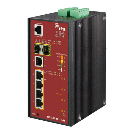
Figure 1: NS3553-4P-1T-2S Industrial L2+ Multi-Port Full Gigabit
Managed Ethernet Switch
Package contents
Thank you for purchasing the NS3553-4P-1T-2S IFS L2+
industrial managed switch. The description of this model is as
follows:
Industrial L2+ 4-Port 10/100/1000T Ultra PoE
+ 1-Port 10/100/1000T
+ 2-Port 100/1000X SFP Managed Switch
Unless specified, the term "industrial managed switch"
mentioned in this quick installation guide refers to the NS3553-
4P-1T-2S.
Open the box of the industrial managed switch and carefully
unpack it. The box should contain the following items:
The industrial managed switch × 1
Quick installation guide × 1
CD with user manual × 1
DIN rail kit × 1
Wall mounting kit × 1
DB9 to RJ45 interface RS232 console cable × 1
Dust cap (see the table below)
RJ45 Dust Cap
NS3553-4P-1T-2S
If any of these are missing or damaged, contact your dealer
immediately. If possible, retain the carton including the original
packing materials for repacking the product in case there is a
need to return it to us for repair.
© 2019 United Technologies Corporation.
Interlogix is part of UTC Climate, Controls & Security, a unit of United Technologies Corporation. All rights reserved. All trademarks are the property
of their respective owners. Information in this document is subject to change without notice.
SFP Dust Cap
6
2
Requirements
The industrial managed switch
interface for management purposes. The following equipment
is necessary for further management:
Workstations running Windows
2008 / 10, MAC OS X or later, Linux, UNIX, or other
platforms are compatible with TCP/IP protocols.
Workstations are installed with Ethernet NIC (Network
Interface Card)
Serial port connection (Terminal)
The above workstations come with a COM Port (DB9)
or USB-to-RS-232 converter.
The above workstations have been installed with a
terminal emulator, such as Hyper Terminal included in
Windows XP/2003.
Serial cable – One end is attached to the RS232
serial port, and the other end is attached to the
console port of the managed switch.
Ethernet port connection
Network cables – Use standard network (UTP) cables
with RJ45 connectors.
The above workstations have a Web browser and
JAVA runtime environment plug-in installed.
Note: We recommend using Internet Explorer 11.0 or later to
access the industrial managed switch. If the Web interface of
the managed switch is not accessible, turn off the anti-virus
software or firewall and then try it again.
Wiring the power inputs
The upper panel of the industrial managed switch indicates a
DC inlet power socket and consists of one terminal block
connector within six contacts. Follow the steps below to insert
the power wire:
1.
Insert the positive/negative DC power wires into contacts 1
and 2 for Power 1, or 5, and 6 for Power 2.
NS3553-4P-1T-2S: DC 48 to 56 V
P/N 1073389-EN • REV B • ISS 01FEB19
provides a
remote login
®
XP / 2003 / Vista / 7 / 8 /
Advertisement

Related Manuals for Interlogix NS3553-4P-1T-2S


Summary of Contents for Interlogix NS3553-4P-1T-2S
- Page 1 P/N 1073389-EN • REV B • ISS 01FEB19 Interlogix is part of UTC Climate, Controls & Security, a unit of United Technologies Corporation. All rights reserved. All trademarks are the property of their respective owners. Information in this document is subject to change without notice.
- Page 2 Ensure that the DIN-rail is secured to the track. Power 1 Power 2 Positive (+) Pin Negative (-) Pin NS3553-4P-1T-2S Pin 1/5 Pin 2/6 Note: The wire gauge for the terminal block should be in the range from 12 to 24 AWG.
-
Page 3: Terminal Setup
Remove the DIN-rail from the industrial gigabit Ethernet switch. Loosen the screws to remove the DIN-rail. Place the wall-mount plate on the rear panel of the industrial gigabit Ethernet switch. Log in to the console. After the terminal has been connected to the device, power on the industrial managed Use the screws to screw the wall-mount plate on the switch. -
Page 4: Starting Web Management
At the “#” prompt, type the following command and press Enter as shown in Figure 5. NS3553-4P-1T-2S # configure terminal NS3553-4P-1T-2S (config)# interface vlan 1 Starting web management NS3553-4P-1T-2S (config-if-vlan)# ip address 192.168.1.100 255.255.255.0 The section describes how to start up the web management function for the industrial managed switch. -
Page 5: Resetting The Switch To Default
Figure 9: Login screen To save all applied changes and set the current configuration as a startup configuration, the startup-configuration file is loaded automatically across a system reboot. Click System > Save Startup Config. After typing the password, the main screen appears as shown in Figure 10 below. -
Page 6: Contact Information
Contact information North America +1 855.286.8889 techsupport@interlogix.com www.interlogix.com/support Latin America +1 561-998-6114 latam@interlogix.com Europe, Middle East, and Africa Select Contact Us at www.utcfssecurityproducts.eu Australia security.tech.support@interlogix.com.au 6 / 6 P/N 1073389-EN • REV B • ISS 01FEB19...