
Related Manuals for Interlogix NS3550-8T-2S


Summary of Contents for Interlogix NS3550-8T-2S
- Page 1 NS3550-8T-2S Industrial Managed Switch User Manual P/N 1072687-EN • REV E • ISS 25JAN19...
- Page 2 Copyright © 2019 United Technologies Corporation. Interlogix is part of UTC Climate, Controls & Security, a unit of United Technologies Corporation. All rights reserved. Trademarks and patents Trade names used in this document may be trademarks or registered trademarks of the manufacturers or vendors of the respective products.
-
Page 3: Table Of Contents
Access Control Lists (ACL) 174 Authentication 188 Security 222 MAC address table 238 LLDP 244 Network diagnostics 258 Loop protection 263 RMON 265 Ring 274 Chapter 5 Command line interface 288 Accessing the CLI 288 Telnet login 288 NS3550-8T-2S Industrial Managed Switch User Manual... - Page 4 VLAN Control List Command 440 SMTP Command 443 Chapter 7 Switch operation 446 Address table 446 Learning 446 Forwarding and filtering 446 Store-and-forward 446 Auto-negotiation 447 Chapter 8 Troubleshooting 448 Appendix A Networking connection 450 Glossary 452 NS3550-8T-2S Industrial Managed Switch User Manual...
-
Page 5: Important Information
Note: Note messages advise you of the possible loss of time or effort. They describe how to avoid the loss. Notes are also used to point out important information that you should read. NS3550-8T-2S Industrial Managed Switch User Manual... -
Page 6: Introduction
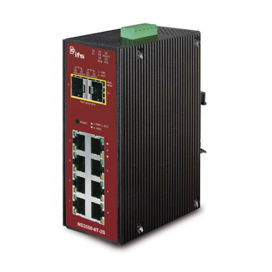
Chapter 1 Introduction The description of the IFS NS3550-8T-2S model is as follows: Industrial L2+ 8-port 10/100/1000T + 2-port 100/1000X managed switch Unless specified, the term “industrial managed switch” mentioned in this user manual refers to the NS3550-8T-2S. -
Page 7: Product Description
With its IP30 aluminum case, the industrial managed switch provides a high level of immunity against electromagnetic interference and heavy electrical surges which are usually found on plant floors or in curb-side traffic control cabinets. It also possesses an NS3550-8T-2S Industrial Managed Switch User Manual... -
Page 8: Product Features
12 to 48 VDC, redundant power with polarity reverse protect function • AC 24 V power adapter acceptable • Supports EFT protection 6000 VDC for power line • Supports Ethernet ESD protection for 6000 VDC • -40 to 75°C operating temperature NS3550-8T-2S Industrial Managed Switch User Manual... - Page 9 Supports Ethernet Ring Protection Switching (ERPS) Quality of Service • Ingress shaper and egress rate limit per port bandwidth control • Eight priority queues on all switch ports • Traffic classification: IEEE 802.1p CoS NS3550-8T-2S Industrial Managed Switch User Manual...
- Page 10 IP source guard prevents IP spoofing attacks. • Auto DoS rule to defend against DoS attacks. • IP address access management to prevent unauthorized intruders. Management • Switch management interfaces: − Remote Telnet management NS3550-8T-2S Industrial Managed Switch User Manual...
-
Page 11: Product Specifications
Two 100/1000BASE-SX/LX/BX SFP interfaces (Port-9 and Port-10) SFP+ Slots Compatible with 100Base-FX SFP Switch Architecture Store-and-Forward Switch Fabric 20 Gbps / non-blocking Throughput 14.8 Mpps Address Table 8K entries, automatic source address learning and aging Shared Data Buffer 512 KB NS3550-8T-2S Industrial Managed Switch User Manual... - Page 12 Flow control disable/enable Power saving mode control Display each port’s speed duplex mode, link status, flow control status, auto- Port Status negotiation status, trunk status. TX / RX / both Port Mirroring Many-to-1 monitor NS3550-8T-2S Industrial Managed Switch User Manual...
- Page 13 IEEE 802.1D Spanning Tree Protocol IEEE 802.1w Rapid Spanning Tree Protocol IEEE 802.1s Multiple Spanning Tree Protocol IEEE 802.1p Class of service IEEE 802.1Q VLAN Tagging IEEE 802.1x Port Authentication Network Control IEEE 802.1ab LLDP NS3550-8T-2S Industrial Managed Switch User Manual...
- Page 14 RFC-2618 RADIUS Client MIB RFC-2933 IGMP-STD-MIB RFC3411 SNMP-Frameworks-MIB IEEE 802.1X PAE LLDP MAU-MIB Environment Temperature: -40 to 75°C Operating Relative Humidity: 5 to 95% (non-condensing) Temperature: -40 to 85°C Storage Relative Humidity: 5 to 95% (non-condensing) NS3550-8T-2S Industrial Managed Switch User Manual...
-
Page 15: Installation
LED indicators. Please read this chapter completely before connecting any network device to the industrial managed switch,. Hardware description The industrial managed switch provides three different running speeds – 10Mbps, 100Mbps, and 1000Mbps, and automatically distinguishes the speed of the incoming connection. NS3550-8T-2S Industrial Managed Switch User Manual... - Page 16 Chapter 2: Installation Physical dimensions Dimensions (W x D x H): 87.8 x 135 x 56 mm NS3550-8T-2S Industrial Managed Switch User Manual...
- Page 17 Located on the upper left side of the front panel, the reset button is designed to reboot the industrial managed switch without turning the power off and on. The following is the summary table of the reset button functions: NS3550-8T-2S Industrial Managed Switch User Manual...
- Page 18 Blinking: indicates that the switch is actively sending or receiving data over that port. 1000 Orange Lit: indicates the port has successfully connected to the network at 1000 Mbps. Blinking: indicates that the switch is actively sending or receiving data over that port. NS3550-8T-2S Industrial Managed Switch User Manual...
- Page 19 Inserting the wires, the industrial managed switch detects the fault status of the power failure, or port link failure. The following illustration shows an application example for wiring the fault alarm contacts. Wires are inserted into the fault alarm contacts. NS3550-8T-2S Industrial Managed Switch User Manual...
-
Page 20: Installing The Industrial Managed Switch
Ensure that the connected network devices support MDI/MDI-X. If they do not support this, use the crossover Category 5 cable. 6. When all connections are set and all LED lights appear normal, the installation is complete.. NS3550-8T-2S Industrial Managed Switch User Manual... - Page 21 Follow all the DIN-rail installation steps as shown in the example. To install the DIN rails on the industrial managed switch: 1. Screw the DIN-rail onto the industrial managed switch. 2. Carefully slide the DIN-rail into the track. NS3550-8T-2S Industrial Managed Switch User Manual...
- Page 22 Chapter 2: Installation 3. Ensure that the DIN-rail is tightly attached to the track. To remove the industrial managed switch from the track: Carefully remove the DIN-rail from the track. NS3550-8T-2S Industrial Managed Switch User Manual...
-
Page 23: Cabling
Mbps, or 200 Mbps, and 1000 Mbps or 2000 Mbps after negotiating with the connected device. The industrial managed switch has eight SFP interfaces that support 100/1000 Mbps dual speed mode (optional multi-mode/single-mode 100BASE-FX/1000BASE-SX/LX SFP module) NS3550-8T-2S Industrial Managed Switch User Manual... - Page 24 SFP port without having to power down the industrial managed switch (see below). Approved Interlogix SFP transceivers The industrial managed switch supports both single mode and multi-mode SFP transceivers. The following list of approved Interlogix SFP transceivers is valid as of the time of publication: Optical Optical...
- Page 25 30 km 0 to +50°C 1310 nm -2 ~ +3 Mode (18.6 mi.) (32 to 122°F) S35-2SLC- Single 30 km -40 to +75°C 1310 nm -2 ~ +3 Mode (18.6 mi.) (-40 to 167°F) NS3550-8T-2S Industrial Managed Switch User Manual...
- Page 26 * Note: High Power Optic. There must be a minimum of 5 dB of optical loss to the fiber for proper operation. Note: We recommend the use of Interlogix SFPs on the industrial managed switch. If you insert an SFP transceiver that is not supported, the industrial managed switch will not recognize it.
- Page 27 Or, through the management interface of the switch/converter (if available), disable the port in advance. 2. Carefully remove the fiber optic cable. 3. Turn the lever of the transceiver module to a horizontal position. 4. Pull out the module gently through the lever. NS3550-8T-2S Industrial Managed Switch User Manual...
- Page 28 Never pull out the module without making use of the lever or the push bolts on the module. Removing the module with force could damage the module and the SFP module slot of the industrial managed switch. NS3550-8T-2S Industrial Managed Switch User Manual...
-
Page 29: Switch Management
An external SNMP-based network management application The remote Telnet and web browser interfaces support are embedded in the industrial managed switch software and are available for immediate use. The advantages of these management methods are described below: NS3550-8T-2S Industrial Managed Switch User Manual... -
Page 30: Remote Telnet
When this method is used, you can access the industrial managed switch remote telnet interface from a personal computer or workstation in the same Ethernet environment as long as you know the current IP address of the industrial managed switch. NS3550-8T-2S Industrial Managed Switch User Manual... -
Page 31: Web Management
You can use a web browser to list and manage the industrial managed switch configuration parameters from one central location, just as if you were directly connected to the industrial managed switch's console port. Web management requires Microsoft Internet Explorer 8.0 or later. NS3550-8T-2S Industrial Managed Switch User Manual... -
Page 32: Snmp-Based Network Management
MIBs. However, if it only knows the get community string, it can only read MIBs. The default get and set community strings for the industrial managed switch are public. NS3550-8T-2S Industrial Managed Switch User Manual... -
Page 33: Web Management
192.168.1.1 with subnet mask 255.255.255.0 via the console, then the administrator computer should be set at 192.168.1.x (where x is a number between 2 and 254) to do the relative configuration on a manager computer. NS3550-8T-2S Industrial Managed Switch User Manual... - Page 34 Note: For security purposes, change and memorize the new password after this first setup. NS3550-8T-2S Industrial Managed Switch User Manual...
-
Page 35: Main Web
The administrator can set up the industrial managed switch by making selections from the main functions menu. Clicking on a main menu item opens sub menus. NS3550-8T-2S Industrial Managed Switch User Manual... -
Page 36: System
This list contains the following items: System information The System Infomation page provides information on the current device such as the hardware MAC address, software version, and system uptime. NS3550-8T-2S Industrial Managed Switch User Manual... - Page 37 This will undo any changes made locally. IP configuration This page includes the IP Address, Subnet Mask, and IP Gateway. The configured column is used to view or change the IP configuration. NS3550-8T-2S Industrial Managed Switch User Manual...
- Page 38 • Click Reset to undo any changes made locally and revert to previously saved values. • Click Renew to renew the DHCP Client. This button is only available if DHCP Client is enabled. NS3550-8T-2S Industrial Managed Switch User Manual...
- Page 39 Click Reset to undo any changes made locally and revert to previously saved values. • Click Renew to renew the IPv6 Auto Configuration. This button is only available if IPv6 Auto Configuration is enabled. NS3550-8T-2S Industrial Managed Switch User Manual...
- Page 40 10 for a standard user account, and privilege level 5 for a guest account. Buttons: • Click Add New User to add a new user Add/edit user Add, edit, or delete a user in this page. NS3550-8T-2S Industrial Managed Switch User Manual...
- Page 41 10 seconds and then release it. The current settings, including VLAN, will be erased and the industrial managed switch restores to default mode. NS3550-8T-2S Industrial Managed Switch User Manual...
- Page 42 This page provides an overview of the privilege levels. After setup is complete, click the Apply button and log in to the web interface with the new user name and password. The following appears: NS3550-8T-2S Industrial Managed Switch User Manual...
- Page 43 Configure NTP on this page. NTP is an acronym for Network Time Protocol, a network protocol for synchronizing the clocks of computer systems. NTP uses UDP (data grams) as a transport layer. You can specify NTP servers and GMT time zone in this page. NS3550-8T-2S Industrial Managed Switch User Manual...
- Page 44 It is convenient for areas in close commercial or other communication to maintain the same time, so time zones tend to follow the boundaries of countries and their subdivisions. Configure the time zone on the Time Zone Configuration page. NS3550-8T-2S Industrial Managed Switch User Manual...
- Page 45 Hours - Select the ending hour. Minutes - Select the ending minute Offset Settings Enter the number of minutes (1 to 1440) to add during Daylight Saving Time. Buttons • Click Save to apply changes. NS3550-8T-2S Industrial Managed Switch User Manual...
- Page 46 30 seconds. Valid values are in the range 100 to 86400. Buttons • Click Save to save changes. • Click Reset to undo any changes made locally and revert to previously saved values. NS3550-8T-2S Industrial Managed Switch User Manual...
- Page 47 The parameter of "port_no" is the fourth byte and it means the port number. The remote ID is six bytes in length, and the value equals the DHCP relay agent’s MAC address. Configure DHCP relay in the DHCP Relay Configuration page. NS3550-8T-2S Industrial Managed Switch User Manual...
- Page 48 Drop: Drop the package when receiving a DHCP message that already contains relay information. Buttons • Click Save to save changes. • Click Reset to undo any changes made locally and revert to previously saved values. NS3550-8T-2S Industrial Managed Switch User Manual...
- Page 49 Keep Agent Option The number of packets received is kept with the relay agent information option. Drop Agent Option The number of packets received is dropped with the relay agent information option. NS3550-8T-2S Industrial Managed Switch User Manual...
- Page 50 If the browser does not display anything on this page, download the Adobe SVG tool and install it in the computer. System log The System Log Information page shows the industrial managed switch system log information. NS3550-8T-2S Industrial Managed Switch User Manual...
- Page 51 • Click Hide to hide the selected log entries. • Click Download to download the selected log entries. • Click I<< to update the system log entries, starting from the first available entry ID. NS3550-8T-2S Industrial Managed Switch User Manual...
- Page 52 • Click >>I to update the system log entries, ending at the last available entry ID. • Click Print to print the system log entry to the current entry ID. NS3550-8T-2S Industrial Managed Switch User Manual...
- Page 53 Click Save to save changes. • Click Reset to undo any changes made locally and revert to previously saved values. SMTP configuration The SMTP Configuration page displays the industrial managed switch SMTP configuration details. NS3550-8T-2S Industrial Managed Switch User Manual...
- Page 54 The time it takes to power up the circuits is known as wakeup time. The default wakeup time is 17 us for 1G bit links and NS3550-8T-2S Industrial Managed Switch User Manual...
- Page 55 Controls whether or not EEE is enabled for this switch port. EEE Urgent Queues Queues set activate transmission of frames as soon as any data is available. Otherwise, the queue postpones the transmission until 3000 bytes, are ready to be transmitted. NS3550-8T-2S Industrial Managed Switch User Manual...
- Page 56 The TFTP Firmware Upgrade page permits a user to update the industrial managed switch firmware from the TFTP server in the network. Before updating, make sure you have your TFTP server ready and that the firmware image is on the TFTP server. NS3550-8T-2S Industrial Managed Switch User Manual...
- Page 57 Save configuration with the exception of the IP address, which will not be saved. You can save/view or load the switch configuration. The configuration file is in XML format with a hierarchy of tags: NS3550-8T-2S Industrial Managed Switch User Manual...
- Page 58 This means that the age time will be set to 200 and the learn mode will be set to automatic. Save configuration 1. Click Save configuration. The following screen appears: 2. Select the path to save the file in the management workstation. NS3550-8T-2S Industrial Managed Switch User Manual...
- Page 59 This Configuration Upload page permits backup and reload of the current configuration of the industrial managed switch to the local management station. 1. Click Browse. The Choose file window appears. 2. Select the configuration file and then click Open. 3. Click Upload. NS3550-8T-2S Industrial Managed Switch User Manual...
- Page 60 Activate Alternate Image to use the alternate image. This button may be disabled depending on the system state. After clicking Activate Alternate Image, click OK to restart the system and use the alternate image. NS3550-8T-2S Industrial Managed Switch User Manual...
- Page 61 You can log in to the management web interface within the same subnet of 192.168.0.xx. System reboot The Restart Device page permits the device to be rebooted from a remote location. After clicking the button to restart, log in to the web interface about 60 seconds later. NS3550-8T-2S Industrial Managed Switch User Manual...
-
Page 62: Simple Network Management Protocol (Snmp)
Collections of related managed objects are defined in specific MIB modules. • Network-management protocol: A management protocol is used to convey management information between agents and NMSs. SNMP is the Internet community's de facto standard management protocol. NS3550-8T-2S Industrial Managed Switch User Manual... - Page 63 Configure SNMPv3 users table on this page. SNMPv3 Groups Configure SNMPv3 groups table on this page. SNMPv3 Views Configure SNMPv3 views table on this page. SNMPv3 Access Configure SNMPv3 accesses table on this page. NS3550-8T-2S Industrial Managed Switch User Manual...
- Page 64 SNMPv3 communities table. It provides more flexibility to configure a security name than a SNMPv1 or SNMPv2c community string. In addition to the community string, a particular range of source addresses can be used to restrict the source subnet. NS3550-8T-2S Industrial Managed Switch User Manual...
- Page 65 It can also represent a legally valid IPv4 address. For example, '::192.1.2.34'. Trap Authentication Failure Indicates the SNMP entity is permitted to generate authentication failure traps. Selections include: NS3550-8T-2S Industrial Managed Switch User Manual...
- Page 66 (-). No space characters are permitted as part of a name. The first character must be an alpha character. And the first or last character must not be a minus sign. The allowed string length is 0 to 255. NS3550-8T-2S Industrial Managed Switch User Manual...
- Page 67 Indicates the SNMP access source address mask. Buttons • Click Add New Entry to add a new community entry. • Click Save to save changes. • Click Reset to undo any changes made locally and revert to previously saved values. NS3550-8T-2S Industrial Managed Switch User Manual...
- Page 68 Authentication Password A string identifying the authentication pass phrase. For MD5 authentication protocol, the allowed string length is 8 to 32. For SHA authentication protocol, the allowed string length is 8 to 40. The NS3550-8T-2S Industrial Managed Switch User Manual...
- Page 69 Indicates the security model that this entry should belong to. Selections include: v1: Reserved for SNMPv1. v2c: Reserved for SNMPv2c. usm: User-based Security Model (USM). Security Name A string identifying the security name that this entry should belong to. NS3550-8T-2S Industrial Managed Switch User Manual...
- Page 70 OID Subtree The OID defining the root of the subtree to add to the named view. The allowed OID length is 1 to 128. The allowed string content is digital number or asterisk (*). NS3550-8T-2S Industrial Managed Switch User Manual...
- Page 71 The name of the MIB view defining the MIB objects for which this request may potentially SET new values. The allowed string length is 1 to 32, and the allowed content is the ASCII characters from 33 to 126. NS3550-8T-2S Industrial Managed Switch User Manual...
-
Page 72: Port Management
This is the logical port number for this row. Port Description Indicates the per port description. Link The current link state is displayed graphically. Green indicates the link is up and red is down. NS3550-8T-2S Industrial Managed Switch User Manual... - Page 73 Buttons • Click Save to save changes. • Click Reset to undo any changes made locally and revert to previously saved values. • Click Refresh to refresh the page and undo all local changes. NS3550-8T-2S Industrial Managed Switch User Manual...
- Page 74 The displayed counters are the totals for receive and transmit, the size counters for receive and transmit, and the error counters for receive and transmit. NS3550-8T-2S Industrial Managed Switch User Manual...
- Page 75 The number of received and transmitted (good and bad) packets split into categories based on their respective frame sizes. Receive and transmit queue counters The number of received and transmitted packets per input and output queue. NS3550-8T-2S Industrial Managed Switch User Manual...
- Page 76 You can also use the port number hyperlinks to check the statistics on a specific interface. NS3550-8T-2S Industrial Managed Switch User Manual...
- Page 77 The industrial managed switch can unobtrusively mirror traffic from any port to a monitor port. You can then attach a protocol analyzer or RMON probe to this port to perform traffic analysis and verify connection integrity. NS3550-8T-2S Industrial Managed Switch User Manual...
- Page 78 The traffic to be copied to the mirror port is selected as follows: • All frames received on a given port (also known as ingress or source mirroring). • All frames transmitted on a given port (also known as egress or destination mirroring). Mirror port configuration NS3550-8T-2S Industrial Managed Switch User Manual...
-
Page 79: Link Aggregation
Link Aggregation Control Protocol (LACP) LAGs – LACP LAGs negotiate aggregated port links with other LACP ports located on a different device. If the other device ports are also LACP ports, the devices establish a LAG between them. NS3550-8T-2S Industrial Managed Switch User Manual... - Page 80 It allows a maximum of 10 ports to be aggregated at the same time. The industrial managed switch supports Gigabit Ethernet ports (up to five groups). If the group is defined as a LACP static link aggregationing group, then any extra ports selected are NS3550-8T-2S Industrial Managed Switch User Manual...
- Page 81 Select the check box to enable the use of the Destination MAC Address, or uncheck it to disable. By default, the Destination MAC Address is disabled. IP Address The IP address can be used to calculate the destination port for the NS3550-8T-2S Industrial Managed Switch User Manual...
- Page 82 LAG. This page allows the user to inspect and change the current LACP port configurations. The LACP port settings relate to the current device, as reflected by the page header. NS3550-8T-2S Industrial Managed Switch User Manual...
- Page 83 Lower number means greater priority. Buttons • Click Save to save changes. • Click Reset to undo any changes made locally and revert to previously saved values. NS3550-8T-2S Industrial Managed Switch User Manual...
- Page 84 LACP port status The LACP Status page provides a LACP status overview of all ports. This page displays the current LACP aggregation groups and LACP port status. NS3550-8T-2S Industrial Managed Switch User Manual...
- Page 85 • Select the Auto-refresh check box to automatically refresh the page every three seconds. LACP port statistics The LACP Statistics page provides an overview of LACP statistics for all ports. NS3550-8T-2S Industrial Managed Switch User Manual...
-
Page 86: Vlan
VLANs. 2. The industrial managed switch supports IEEE 802.1Q VLAN. The port untagging function can be used to remove the 802.1 tag from packet headers to maintain compatibility with devices that are tag-unaware. NS3550-8T-2S Industrial Managed Switch User Manual... - Page 87 Up to 255 VLANs based on the IEEE 802.1Q standard. • Port overlapping, allowing a port to participate in multiple VLANs. • End stations can belong to multiple VLANs. • Passing traffic between VLAN-aware and VLAN-unaware devices. • Priority tagging NS3550-8T-2S Industrial Managed Switch User Manual...
- Page 88 VID is 12 bits long, 4094 unique VLAN can be identified. The tag is inserted into the packet header making the entire packet longer by four octets. All of the information originally contained in the packet is retained. NS3550-8T-2S Industrial Managed Switch User Manual...
- Page 89 A switch port can have only one PVID, but can have as many VIDs as the switch has memory in its VLAN table to store them. NS3550-8T-2S Industrial Managed Switch User Manual...
- Page 90 VLANs configured on the switch. Packets are forwarded only between ports that are designated for the same VLAN. Untagged VLANs can be used to manually isolate user groups or subnets. NS3550-8T-2S Industrial Managed Switch User Manual...
- Page 91 Untagged: Ports with untagging enabled strip the 802.1Q tag from all packets that flow into those ports. If the packet doesn't have an 802.1Q VLAN tag, the port will not alter the packet. Thus, all packets received by and forwarded by an untagging port have no NS3550-8T-2S Industrial Managed Switch User Manual...
- Page 92 VLAN tags so that the VLANs in the MAN space can be used independent of the customers’ VLANs. This is accomplished by adding a VLAN tag with a MAN-related VID for frames entering the MAN. When leaving NS3550-8T-2S Industrial Managed Switch User Manual...
- Page 93 In cases where a given service VLAN only has two member ports on the switch, the learning can be disabled for the particular VLAN and can therefore rely on flooding as the forwarding mechanism between the two ports. This way, the MAC table requirements are reduced. VLAN port configuration NS3550-8T-2S Industrial Managed Switch User Manual...
- Page 94 The port must be a member of the same VLAN as the Port VLAN ID. Buttons • Click Save to save changes. • Click Reset to undo any changes made locally and revert to previously saved values. NS3550-8T-2S Industrial Managed Switch User Manual...
- Page 95 VLAN without any port members on any stack unit will be deleted when you click Save. The button can be used to undo the addition of new VLANs. Buttons • Click Add New VLAN to add a new VLAN. NS3550-8T-2S Industrial Managed Switch User Manual...
- Page 96 VLAN port configuration such as PVID and UVID. Currently we support following VLAN s: CLI/Web/SNMP: This is referred as static. NAS: NAS provides port-based authentication, which involves communications between a Supplicant, Authenticator, and an NS3550-8T-2S Industrial Managed Switch User Manual...
- Page 97 VLAN ID). • Click >> to update the table, starting with the entry after the last entry currently displayed. VLAN port status The VLAN Port Status for Static User page provides VLAN port status. NS3550-8T-2S Industrial Managed Switch User Manual...
- Page 98 By default, all ports are VLAN unaware and are members of VLAN 1 and private VLAN 1. A VLAN unaware port can only be a member of one VLAN, but it can be a member of multiple private VLANs. NS3550-8T-2S Industrial Managed Switch User Manual...
- Page 99 • Click Save to save changes. • Click Reset to undo any changes made locally and revert to previously saved values. • Click Refresh to refresh the page immediately. NS3550-8T-2S Industrial Managed Switch User Manual...
- Page 100 Ports that can receive traffic from all ports in the private VLAN. Isolated ports • Ports from which traffic can only be forwarded to promiscuous ports in the private VLAN. • Ports that can receive traffic from only promiscuous ports in the private VLAN. NS3550-8T-2S Industrial Managed Switch User Manual...
- Page 101 Automatic refresh occurs every three seconds. • Click Refresh to refresh the page immediately. VLAN setting examples This section covers the following setup scenarios: • Separate VLAN • 802.1Q VLAN Trunk • Port Isolate NS3550-8T-2S Industrial Managed Switch User Manual...
- Page 102 2. [PC-4],[PC-5] and [PC-6] received no packet. 3. While the packet leaves Port-2, it will be stripped away, becoming an untagged packet. 4. While the packet leaves Port-3, it will remain as a tagged packet with VLAN Tag=2. NS3550-8T-2S Industrial Managed Switch User Manual...
- Page 103 6 has been assigned to VLAN 2 and VLAN 3. Note: It’s important to remove the VLAN members from VLAN 1 configuration, otherwise the ports will have overlapping setting (see the next VLAN configure sample). 4. Assign PVID to each port: NS3550-8T-2S Industrial Managed Switch User Manual...
- Page 104 VLAN trunking between two 802.1Q-aware switches In most cases, they are used for “Uplink” to other switches. VLANs are separated at different switches, but they need access to other switches within the same VLAN group. NS3550-8T-2S Industrial Managed Switch User Manual...
- Page 105 3. Define a VLAN 1 as a “Public Area” that overlaps with both VLAN 2 members and VLAN 3 members. 4. Assign the VLAN Trunk Port to being the member of each VLAN to be aggregated. For example, assign Port-8 to be VLAN 2 and VLAN 3 member ports. NS3550-8T-2S Industrial Managed Switch User Manual...
- Page 106 However, each computer requires access to the same server/AP/Printer. This section explains how to configure the port for the server so that it can be accessed by each isolated port. NS3550-8T-2S Industrial Managed Switch User Manual...
- Page 107 The MAC-based VLAN entries can be configured on the MAC-based VLAN Membership Configuration page. This page allows for adding and deleting MAC-based VLAN entries and assigning the entries to different ports. This page shows only static entries. NS3550-8T-2S Industrial Managed Switch User Manual...
- Page 108 >> to update the table, starting with the entry after the last entry currently displayed. MAC-based VLAN status The MAC-based VLAN Membership Status page shows MAC-based VLAN entries configured by various MAC-based VLAN users NS3550-8T-2S Industrial Managed Switch User Manual...
- Page 109 The Protocol to Group Mapping Table page permits the addition of new protocols to the Group Name (unique for each Group) mapping entries, and allows you to see and delete entries already mapped for the switch. NS3550-8T-2S Industrial Managed Switch User Manual...
- Page 110 • Select the Auto-refresh check box to refresh the page automatically. Automatic refresh occurs every three seconds. • Click Refresh to refresh the page immediately. NS3550-8T-2S Industrial Managed Switch User Manual...
- Page 111 • Select the Auto-refresh check box to refresh the page automatically. Automatic refresh occurs every three seconds. • Click Refresh to refresh the page immediately. NS3550-8T-2S Industrial Managed Switch User Manual...
-
Page 112: Spanning Tree Protocol (Stp)
Bridge protocol data units For STP to arrive at a stable network topology, the following information is used: • The unique switch identifier. • The path cost to the root associated with each switch port. NS3550-8T-2S Industrial Managed Switch User Manual... - Page 113 Each port on a switch using STP exists is in one of the following five states: NS3550-8T-2S Industrial Managed Switch User Manual...
- Page 114 If properly configured, each port stabilizes to the forwarding or blocking state. No packets (except BPDUs) are forwarded from, or received by, STP-enabled ports until the forwarding state is enabled for that port. NS3550-8T-2S Industrial Managed Switch User Manual...
- Page 115 STP calculates path costs and selects the 20,000-1000Mbps Gigabit Ethernet ports path with the minimum cost as the active 0 - Auto path Default spanning-tree configuration Feature Default Value Enable state STP disabled for all ports Port priority NS3550-8T-2S Industrial Managed Switch User Manual...
- Page 116 Illustration of STP A simple illustration of three switches connected in a loop is depicted in the following diagram. In this example, you can anticipate some major network problems if the STP assistance is not applied. NS3550-8T-2S Industrial Managed Switch User Manual...
- Page 117 STP to choose a particular switch as the root bridge using the priority setting, or influencing STP to choose a particular port to block using the port priority and port cost settings is, however, relatively straightforward. In this example, only the default STP values are used: NS3550-8T-2S Industrial Managed Switch User Manual...
- Page 118 RSTP to further develop the usefulness of virtual LANs (VLANs). This "Per-VLAN" MSTP configures a separate spanning tree for each VLAN group and blocks all but one of the possible alternate paths within each spanning tree. NS3550-8T-2S Industrial Managed Switch User Manual...
- Page 119 Transmit Hold Count The number of BPDU's a bridge port can send per second. When exceeded, transmission of the next BPDU is delayed. Valid values are in the range of BPDU's per second. NS3550-8T-2S Industrial Managed Switch User Manual...
- Page 120 Bridge status The STP Bridges page provides a status overview of all STP bridge instances. The table contains a row for each STP bridge instance, and the columns display the following information: NS3550-8T-2S Industrial Managed Switch User Manual...
- Page 121 The time since the last topology change occurred. Buttons • Select the Auto-refresh check box to refresh the page automatically. Automatic refresh occurs every three seconds. • Click Refresh to refresh the page immediately. NS3550-8T-2S Industrial Managed Switch User Manual...
- Page 122 (having operEdge true) than for other ports. The value of this flag is based on AdminEdge and AutoEdge fields. This flag is displayed as Edge in Monitor ->Spanning Tree -> STP Detailed Bridge Status. NS3550-8T-2S Industrial Managed Switch User Manual...
- Page 123 By default, the system automatically detects the speed and duplex mode used on each port and configures the path cost according to the values shown below. Path cost “0” is used to indicate auto-configuration mode. When the short path cost method is selected NS3550-8T-2S Industrial Managed Switch User Manual...
- Page 124 200,000 Full Duplex 100,000 Trunk 50,000 Gigabit Ethernet Full Duplex 10,000 Trunk 5,000 MSTI priorities The MSTI Configuration page permits the user to inspect and change the current STP MSTI bridge instance priority configurations. NS3550-8T-2S Industrial Managed Switch User Manual...
- Page 125 Reset to undo any changes made locally and revert to previously saved values. MSTI configuration The MSTI Configuration page permits the user to inspect and change the current STP MSTI bridge instance priority configurations. NS3550-8T-2S Industrial Managed Switch User Manual...
- Page 126 Chapter 4: Web management NS3550-8T-2S Industrial Managed Switch User Manual...
- Page 127 The MSTI instance must be selected before displaying actual MSTI port configuration options. This page contains MSTI port settings for physical and aggregated ports. The aggregation settings are stack global. NS3550-8T-2S Industrial Managed Switch User Manual...
- Page 128 Priority Controls the port priority. This can be used to control priority of ports having identical port cost. means all ports wil have one specific setting. NS3550-8T-2S Industrial Managed Switch User Manual...
- Page 129 Disabled Blocking Learning Forwarding Non-STP Uptime The time since the bridge port was last initialized. Buttons • Select the Auto-refresh check box to refresh the page automatically. Automatic refresh occurs every three seconds. NS3550-8T-2S Industrial Managed Switch User Manual...
-
Page 130: Multicast
Click Clear to clear the counters for all ports. Multicast IGMP snooping The Internet Group Management Protocol (IGMP) allows hosts and routers share information about multicast groups memberships. IGMP snooping is a switch feature NS3550-8T-2S Industrial Managed Switch User Manual... - Page 131 If there are no members on a sub network, packets will not be forwarded to that sub network. Multicast service NS3550-8T-2S Industrial Managed Switch User Manual...
- Page 132 Chapter 4: Web management Multicast flooding IGMP snooping multicast stream control NS3550-8T-2S Industrial Managed Switch User Manual...
- Page 133 LAN, an explicit leave message, and query messages that are specific to a given group. The states a computer will go through to join or to leave a multicast group are as follows: NS3550-8T-2S Industrial Managed Switch User Manual...
- Page 134 Multicast routers use this information, along with a multicast routing protocol such as DVMRP or PIM, to support IP multicasting across the Internet. IGMP snooping configuration The IGMP Snooping Configuration page provides IGMP snooping-related configuration information. NS3550-8T-2S Industrial Managed Switch User Manual...
- Page 135 Enable IGMP leave proxy. This feature can be used to avoid forwarding unnecessary leave messages to the router side. Proxy Enable Enable IGMP proxy. This feature can be used to avoid forwarding unnecessary join and leave messages to the router side. NS3550-8T-2S Industrial Managed Switch User Manual...
- Page 136 When initially accessing the page, it shows the first 20 entries from the beginning of the VLAN table. The first entry shown will be the one with the lowest VLAN ID found in the VLAN table. NS3550-8T-2S Industrial Managed Switch User Manual...
- Page 137 Unsolicited Report Interval. The Unsolicited Report Interval is the time between repetitions of a host's initial report of membership in a group. The allowed range is 31744 seconds, default unsolicited report interval is 1 second. NS3550-8T-2S Industrial Managed Switch User Manual...
- Page 138 “deny” or “replace.” If the action is set to deny, any new IGMP join reports will be dropped. If the action is set to replace, the switch randomly removes an existing group and replaces it with the new multicast group. NS3550-8T-2S Industrial Managed Switch User Manual...
- Page 139 Group Filtering table. • Click Save to save changes. • Click Reset to undo any changes made locally and revert to previously saved values. IGMP snooping status The IGMP Snooping Status page provides IGMP snooping status. NS3550-8T-2S Industrial Managed Switch User Manual...
- Page 140 When initially accessing the page, it shows the first 20 entries from the beginning of the IGMP Group table. The Start from VLAN group Address fields permit the user to select the starting point in the IGMP group table. NS3550-8T-2S Industrial Managed Switch User Manual...
- Page 141 When initially accessing the page, it shows the first 20 entries from the beginning of the IGMP Group table. The Start from VLAN group Address fields permit the user to select the starting point in the IGMP information table. NS3550-8T-2S Industrial Managed Switch User Manual...
- Page 142 IGMP group table. • Click >> to update the table, starting with the entry after the last entry currently shown. MLD snooping configuration The MLD Snooping Configuration page provides MLD snooping-related configuration. NS3550-8T-2S Industrial Managed Switch User Manual...
- Page 143 When initially accessing the page, it shows the first 20 entries from the beginning of the VLAN table. The first entry shown will be the one with the lowest VLAN ID found in the VLAN table. NS3550-8T-2S Industrial Managed Switch User Manual...
- Page 144 Start from VLAN entries per page input fields. • Click I<< to update the table starting from the first entry in the VLAN table (i.e., the entry with the lowest VLAN ID). NS3550-8T-2S Industrial Managed Switch User Manual...
- Page 145 “deny” or “replace.” If the action is set to deny, any new MLD join reports will be dropped. If the action is set to replace, the switch randomly removes an existing group and replaces it with the new multicast group. NS3550-8T-2S Industrial Managed Switch User Manual...
- Page 146 Group Filtering table. • Click Save to save changes. • Click Reset to undo any changes made locally and revert to previously saved values. MLD snooping status The MLD Snooping Status page provides MLD snooping status. NS3550-8T-2S Industrial Managed Switch User Manual...
- Page 147 When initially accessing the page, it shows the first 20 entries from the beginning of the MLD Group table. The Start from VLAN group Address fields permit the user to select the starting point in the MLD group table. NS3550-8T-2S Industrial Managed Switch User Manual...
- Page 148 When initially accessing the page, it shows the first 20 entries from the beginning of the IGMP Group table. The Start from VLAN Group fields permit the user to select the starting point in the MLD information table. NS3550-8T-2S Industrial Managed Switch User Manual...
- Page 149 Uplink ports that send and receive multicast data to and from the multicast VLAN are called MVR source ports. A maximum of eight MVR VLANs with corresponding channel settings can be created for each multicast VLAN. A maximum of 256 group addresses are available for channel settings. NS3550-8T-2S Industrial Managed Switch User Manual...
- Page 150 Chapter 4: Web management The MVR Configurations page provides MVR-related configuration information. NS3550-8T-2S Industrial Managed Switch User Manual...
- Page 151 Receiver: Configure a port as a receiver port if it is a subscriber port and should only receive multicast data. It does not receive data unless it becomes a member of the multicast group by issuing IGMP/MLD messages. Caution: We do not recommend overlapping MVR source ports with NS3550-8T-2S Industrial Managed Switch User Manual...
- Page 152 The number of received IGMPv1 joins and MLDv2 reports, respectively. Reports Received IGMPv2/MLDv1 The number of received IGMPv2 leaves and MLDv1 dones, respectively. Leaves Received Buttons • Click Refresh to refresh the page immediately. • Click Clear to clear all statistics counters. NS3550-8T-2S Industrial Managed Switch User Manual...
-
Page 153: Quality Of Service (Qos)
Quality of Service (QoS) Understanding QoS Quality of Service (QoS) is an advanced traffic prioritization feature that allows you to establish control over network traffic. QoS permits the assignment of various grades of NS3550-8T-2S Industrial Managed Switch User Manual... - Page 154 1. Define a service level to determine the priority that will be applied to traffic. 2. Apply a classifier to determine how the incoming traffic will be classified and thus treated by the industrial managed switch. NS3550-8T-2S Industrial Managed Switch User Manual...
- Page 155 If flow control is enabled and the port is in flow control mode, then pause frames are sent instead of discarding frames. Buttons • Click Save to save changes. • Click Reset to undo any changes made locally and revert to previously saved values. NS3550-8T-2S Industrial Managed Switch User Manual...
- Page 156 Shows "disabled" or actual port shaper rate (e.g., "800 Mbps"). QoS egress port schedule and shapers The port scheduler and shapers for a specific port are configured on the QoS Egress Port Schedule and Shapers page. NS3550-8T-2S Industrial Managed Switch User Manual...
- Page 157 Unit is kbps, and it is restricted to 1- 13200 when the Unit is Mbps. Port Shaper Unit Controls the unit of measure for the port shaper rate as kbps or Mbps. The default value is kbps. NS3550-8T-2S Industrial Managed Switch User Manual...
- Page 158 Controls the default PCP value. All frames are classified to a PCP value. If the port is VLAN-aware and the frame is tagged, then the frame is NS3550-8T-2S Industrial Managed Switch User Manual...
- Page 159 Save to save changes. • Click Reset to undo any changes made locally and revert to previously saved values. QoS ingress port tag classification Configure the classification modes for tagged frames on this page. NS3550-8T-2S Industrial Managed Switch User Manual...
- Page 160 For more details, refer to “Understanding QoS” on page 151. Mode Shows the scheduling mode for this port. Q0 ~ Q5 Shows the weight for this queue and port. NS3550-8T-2S Industrial Managed Switch User Manual...
- Page 161 Mapped: Use mapped versions of QoS class and DP level. QoS egress port tag remarking The QoS Egress Port Tag Remarking page can also provide an overview of QoS egress port tag remarking for a specific port. NS3550-8T-2S Industrial Managed Switch User Manual...
- Page 162 • Click Cancel to return to the previous page. Port DSCP The QoS Port DSCP Configuration page permits configuration of the basic QoS port DSCP settings for all switch ports. NS3550-8T-2S Industrial Managed Switch User Manual...
- Page 163 DSCP-based QoS The QoS DSCP-Based QoS Ingress Classification page permits configuration of the basic QoS DSCP-based QoS ingress classification settings for all switches. NS3550-8T-2S Industrial Managed Switch User Manual...
- Page 164 QoS Class QoS Class values can be between 0-7. Drop Precedence Level (0-1) Buttons • Click Save to save changes. • Click Reset to undo any changes made locally and revert to previously saved values. NS3550-8T-2S Industrial Managed Switch User Manual...
- Page 165 There are two configuration parameters for DSCP Translation: Translate Classify Translate DSCP at the Ingress side can be translated to any of 0-63 DSCP values. Classify Click Classify to enable classification at the Ingress side. NS3550-8T-2S Industrial Managed Switch User Manual...
- Page 166 • Click Reset to undo any changes made locally and revert to previously saved values. DSCP classification The DSCP Classification page permits mapping a DSCP value to a QoS Class and DPL value. NS3550-8T-2S Industrial Managed Switch User Manual...
- Page 167 Displays the OUI field of Source MAC address (i.e., the first three octets (in bytes) of the MAC address). Tag Type Indicates tag type. Selections include: Any: Match tagged and untagged frames. Default value. Untagged: Match untagged frames. NS3550-8T-2S Industrial Managed Switch User Manual...
- Page 168 : Moves the QCE down the list. : Deletes the QCE. : The lowest plus sign adds a new entry at the bottom of the list of QCL. QoS control entry configuration The QCE Configuration page appears as follows: NS3550-8T-2S Industrial Managed Switch User Manual...
- Page 169 Any. DSCP values are in the range 0-63 including BE, CS1- CS7, EF or AF11-AF43. Sport – Source TCP/UDP port:(0-65535) or Any, specific or port range applicable for IP protocol UDP/TCP. NS3550-8T-2S Industrial Managed Switch User Manual...
- Page 170 Any: The QCE will match all frame types. Ethernet: Only Ethernet frames (with Ether Type 0x600-0xFFFF) are allowed. LLC: Only (LLC) frames are allowed. SNAP: Only (SNAP) frames are allowed. IPv4: The QCE will match only IPV4 frames. NS3550-8T-2S Industrial Managed Switch User Manual...
- Page 171 QCL entry is Yes. • Click Refresh to refresh the page. Queue policing Configure the queue policer settings for all switch ports in the QoS Ingress Queue Policers page. NS3550-8T-2S Industrial Managed Switch User Manual...
- Page 172 These only affect flooded frames (i.e., frames with a (VLAN ID, DMAC) pair not present on the MAC Address table). The configuration indicates the permitted packet rate for unicast, multicast, or broadcast traffic across the switch. NS3550-8T-2S Industrial Managed Switch User Manual...
- Page 173 • Click Reset to undo any changes made locally and revert to previously saved values. QoS statistics The Queuing Counters page provides statistics for the different queues for all switch ports. NS3550-8T-2S Industrial Managed Switch User Manual...
- Page 174 We recommended that there be two VLANs on a port – one for voice and one for data. Before connecting the IP device to the switch, the IP phone should configure the voice VLAN ID correctly. It should be configured through its own GUI. NS3550-8T-2S Industrial Managed Switch User Manual...
- Page 175 All: All ports will have one specific setting. Voice VLAN OUI table Configure Voice VLAN OUI table on the Voice VLAN OUI Table page. The maximum entry number is 16. Modifying the OUI table restarts auto detection of the OUI process. NS3550-8T-2S Industrial Managed Switch User Manual...
-
Page 176: Access Control Lists (Acl)
ACL implementations can be quite complex (as when the ACEs are prioritized for various situations). In networking, the ACL refers to a list of service ports or network NS3550-8T-2S Industrial Managed Switch User Manual... - Page 177 Deny: Frames matching the ACE are dropped. Rate Limiter Indicates the rate limiter number of the ACE. The allowed range is 1 to 16. When Disabled is shown, the rate limiter operation is disabled. NS3550-8T-2S Industrial Managed Switch User Manual...
- Page 178 Indicates the ingress port of the ACE. Possible values are: All: The ACE matches all ingress port. Port: The ACE matches a specific ingress port. Policy / Bitmask Indicates the policy number and bitmask of the ACE. NS3550-8T-2S Industrial Managed Switch User Manual...
- Page 179 ACE, and then select the frame type. Different parameter options appear depending on the frame type selected. A frame that hits this ACE matches the configuration that is defined here. NS3550-8T-2S Industrial Managed Switch User Manual...
- Page 180 The permitted range is to 255. Policy Bitmask When Specific is selected for the policy filter, you can enter a specific policy bitmask. The permitted range is to 0xff. NS3550-8T-2S Industrial Managed Switch User Manual...
- Page 181 Disabled: Port shut down is disabled for the ACE. Note: The shutdown feature only works when the packet length is less than 1518 (without VLAN tags). Counter The counter indicates the number of times the ACE was hit by a frame. NS3550-8T-2S Industrial Managed Switch User Manual...
- Page 182 The allowed number range is 0 to 7. The value means that no tag priority is specified (tag priority is "don't-care”). ARP parameters Object Description ARP/RARP Specify the available ARP/RARP opcode (OP) flag for this ACE. NS3550-8T-2S Industrial Managed Switch User Manual...
- Page 183 0: ARP/RARP frames where the HLN is equal to Ethernet (0x06) and the (PLN) is equal to IPv4 (0x04). 1: ARP/RARP frames where the HLN is equal to Ethernet (0x06) and the (PLN) is equal to IPv4 (0x04). Any: Any value is allowed ("don't-care”). NS3550-8T-2S Industrial Managed Switch User Manual...
- Page 184 Yes: IPv4 frames where the MF bit is set or the FRAG OFFSET field is greater than zero must be able to match this entry. Any: Any value is allowed ("don't-care”). NS3550-8T-2S Industrial Managed Switch User Manual...
- Page 185 When Specific is selected for the ICMP code filter, you can enter a specific ICMP code value. The allowed range is to 255. A frame that hits this ACE matches this ICMP code value. NS3550-8T-2S Industrial Managed Switch User Manual...
- Page 186 0: TCP frames where the RST field is set must not be able to match this entry. 1: TCP frames where the RST field is set must be able to match this entry. Any: Any value is allowed ("don't-care”). NS3550-8T-2S Industrial Managed Switch User Manual...
- Page 187 ACL ports configuration Configure the ACL parameters (ACE) of each switch port on the ACL Ports Configuration page. These parameters will affect frames received on a port unless the frame matches a specific ACE. NS3550-8T-2S Industrial Managed Switch User Manual...
- Page 188 Specify the port shut down operation of this port. Selections include: Enabled: If a frame is received on the port, the port will be disabled. Disabled: Port shut down is disabled. The default value is Disabled. means all ports will have one specific setting. NS3550-8T-2S Industrial Managed Switch User Manual...
- Page 189 Any changes made locally are undone. • Click Clear to clear the counters. ACL rate limiter configuration Configure the rate limiter for the ACL of the industrial managed switch on the ACL Rate Limiter Configuration page. NS3550-8T-2S Industrial Managed Switch User Manual...
-
Page 190: Authentication
When authentication is complete, the RADIUS server sends a special packet containing a success or failure indication. Besides forwarding this decision to the supplicant, the switch uses it to open up or block traffic on the switch port connected to the supplicant. NS3550-8T-2S Industrial Managed Switch User Manual... - Page 191 Understanding IEEE 802.1X port-based authentication The IEEE 802.1X standard defines a client-server-based access control and authentication protocol that restricts unauthorized clients from connecting to a LAN through publicly accessible ports. The authentication server authenticates each client NS3550-8T-2S Industrial Managed Switch User Manual...
- Page 192 The switch includes the RADIUS client, which is responsible for encapsulating and decapsulating the Extensible Authentication Protocol (EAP) frames and interacting with the authentication server. When the NS3550-8T-2S Industrial Managed Switch User Manual...
- Page 193 The specific exchange of EAP frames depends on the authentication method being used. The diagram below shows a message exchange initiated by the client using the One-Time-Password (OTP) authentication method with a RADIUS server. NS3550-8T-2S Industrial Managed Switch User Manual...
- Page 194 When a client logs off, it sends an EAPOL-logoff message that causes the switch port to transition to the unauthorized state. If the link state of a port transitions from up to down, or if an EAPOL-logoff frame is received, the port returns to the unauthorized state. NS3550-8T-2S Industrial Managed Switch User Manual...
- Page 195 Network Access Server Configuration page. The IEEE 802.1X standard defines a port-based access control procedure that prevents unauthorized access to a network by requiring users to first submit credentials for authentication. One or more central NS3550-8T-2S Industrial Managed Switch User Manual...
- Page 196 The switch uses the MAC address to authenticate against the back end server. Intruders can create counterfeit MAC addresses, which makes MAC-based authentication less secure than 802.1X authentication. The NAS configuration consists of two sections, a system- and a port-wide. NS3550-8T-2S Industrial Managed Switch User Manual...
- Page 197 "Configuration > Security > AAA" Page), the client is put on hold in the Unauthorized state. The hold timer does not count during an on-going authentication. In MAC-based Auth. mode, the The switch will ignore new frames coming NS3550-8T-2S Industrial Managed Switch User Manual...
- Page 198 (selected), the switch considers entering the Guest VLAN even if an EAPOL frame has been received on the port for the life-time of the port. The value can only be changed if the Guest VLAN option is globally enabled. NS3550-8T-2S Industrial Managed Switch User Manual...
- Page 199 (through a hub, for example) to piggy- back on the successfully authenticated client and get network access even though they really aren't authenticated. To overcome this security breach, NS3550-8T-2S Industrial Managed Switch User Manual...
- Page 200 The disadvantage is that MAC addresses can be spoofed by malicious users - equipment whose MAC address is a valid RADIUS user can be used by NS3550-8T-2S Industrial Managed Switch User Manual...
- Page 201 Private-Group-ID does not need to include a Tag): Value of Tunnel-Medium-Type must be set to "IEEE-802" (ordinal 6). Value of Tunnel-Type must be set to "VLAN" (ordinal 13). Value of Tunnel-Private-Group-ID must be a string of ASCII chars in the NS3550-8T-2S Industrial Managed Switch User Manual...
- Page 202 (EAPOL-based authentication). For MAC-based authentication, reauthentication is attempted immediately. The button only has an effect for successfully authenticated clients on the port and will not cause the clients to get temporarily unauthorized. NS3550-8T-2S Industrial Managed Switch User Manual...
- Page 203 Response Identity EAPOL frame for EAPOL-based authentication, and the source MAC address from the most recently received frame from a new client for MAC-based authentication. QoS Class QoS Class assigned to the port by the RADIUS server if enabled. NS3550-8T-2S Industrial Managed Switch User Manual...
- Page 204 ID is not overridden by NAS. If the VLAN ID is assigned by the RADIUS server, "(RADIUS-assigned)" is appended to the VLAN ID. If the port is moved to the Guest VLAN, "(Guest)" is appended to the VLAN NS3550-8T-2S Industrial Managed Switch User Manual...
- Page 205 The number of EAPOL frames of any type that have been transmitted by the switch. Request ID dot1xAuthEapolReqId The number of EAPOL FramesTx Request Identity frames that have been transmitted by the switch. NS3550-8T-2S Industrial Managed Switch User Manual...
- Page 206 Auth. dot1xAuthBack 802.1X- and MAC-based: endAuthFails Failures Counts the number of times that the switch receives a failure message. This indicates that the supplicant/client has not NS3550-8T-2S Industrial Managed Switch User Manual...
- Page 207 The protocol version number carried in the most recently received EAPOL frame. MAC-based: Not applicable. Identity 802.1X-based: The user name (supplicant identity) carried in the most recently received Response Identity EAPOL frame. MAC-based: Not applicable. NS3550-8T-2S Industrial Managed Switch User Manual...
- Page 208 Refresh to refresh the page immediately. • Click Clear to clear the counters for the selected port. This button is available in the following modes: • Force Authorized • Force Unauthorized • Port-based 802.1X NS3550-8T-2S Industrial Managed Switch User Manual...
- Page 209 This button is available in the following modes: • Multi 802.1X • MAC-based Auth.X Authentication server configuration Configure the authentication servers on the Authentication Server Configuration page. NS3550-8T-2S Industrial Managed Switch User Manual...
- Page 210 The IP address or hostname of the TACACS+ authentication server. IP Address/Hostname address is expressed in dotted decimal notation. Port The UDP port to use on the TACACS+ authentication server. If the port is NS3550-8T-2S Industrial Managed Switch User Manual...
- Page 211 RADIUS overview The RADIUS Authentication/Accounting Server Overview page provides an overview of the status of the RADIUS servers configurable on the authentication configuration page. NS3550-8T-2S Industrial Managed Switch User Manual...
- Page 212 This state is only reachable when more than one server is enabled. Buttons • Click Refresh to refresh the page immediately. • Click Auto-refresh to refresh the page automatically. Automatic refresh occurs every three seconds. NS3550-8T-2S Industrial Managed Switch User Manual...
- Page 213 RADIUS authentication statistics The statistics map closely to those specified in RFC4668 - RADIUS Authentication Client MIB. Use the server select box to switch between the back end servers to show details for each. NS3550-8T-2S Industrial Managed Switch User Manual...
- Page 214 Access radiusAuthClientEx The number of RADIUS Requests tAccessRequests Access-Request packets sent to the server. This does not include retransmissions. Access radiusAuthClientEx The number of RADIUS Retransmissi tAccessRetransmis Access-Request packets retransmitted to the NS3550-8T-2S Industrial Managed Switch User Manual...
- Page 215 Round-Trip radiusAuthClie The time interval (measured in milliseconds) Time ntExtRoundTrip between the most recent Access-Reply/Access- Time Challenge and the Access-Request that matched it from the RADIUS authentication NS3550-8T-2S Industrial Managed Switch User Manual...
- Page 216 The number of RADIUS tRequests packets sent to the server. This does not include retransmissions. Retransmissions radiusAccClientEx The number of RADIUS tRetransmissions packets retransmitted to the RADIUS accounting server. Pending radiusAccClientEx The number of RADIUS NS3550-8T-2S Industrial Managed Switch User Manual...
- Page 217 Response and the Request that matched it from the RADIUS accounting server. The granularity of this measurement is 100 ms. A value of 0 ms indicates that there has yet to be round-trip communication with the server. NS3550-8T-2S Industrial Managed Switch User Manual...
- Page 218 802.1x system configuration (12345678 in this case). 1. Configure the IP Address of remote RADIUS server and secret key. 2. Click New RADIUS Client on the Windows 2003 server. NS3550-8T-2S Industrial Managed Switch User Manual...
- Page 219 Chapter 4: Web management 3. Assign the client IP address to the industrial managed switch. 4. The shared secret key should be as same as the key configured on the industrial managed switch. NS3550-8T-2S Industrial Managed Switch User Manual...
- Page 220 Radius Server PC. For example, select Active Directory Users and Computers and create legal user data (Windows Server 2003). 7. Right-click a user that you created and then type in properties and configure settings. NS3550-8T-2S Industrial Managed Switch User Manual...
- Page 221 Otherwise, the switch might not be able to access the RADIUS server after the 802.1X starts to work. 802.1X client configuration Windows XP has native support for 802.1X. The following procedures show how to configure 802.1X Authentication in Windows XP. NS3550-8T-2S Industrial Managed Switch User Manual...
- Page 222 Properties setting window. 4. Click the Authentication tab. 5. Select Enable network access control using IEEE 802.1X to enable 802.1x authentication. 6. Select MD-5 Challenge from the drop-down list box for EAP type. NS3550-8T-2S Industrial Managed Switch User Manual...
- Page 223 Click on the notice to continue. 9. Type the user name, password and the logon domain that your account belongs to. 10. Click to complete the validation process. NS3550-8T-2S Industrial Managed Switch User Manual...
-
Page 224: Security
The limit control module utilizes a lower-layer port security module that manages MAC addresses learned on the port. The limit control configuration consists of two sections, a system- and a port-wide. NS3550-8T-2S Industrial Managed Switch User Manual... - Page 225 The end-host will be allowed to forward if the limit is not exceeded. Now suppose that the end-host logs off or powers down. If it wasn't for aging, the end-host would still take up resources on this switch and will be allowed to NS3550-8T-2S Industrial Managed Switch User Manual...
- Page 226 Action is set to None or Trap. Shutdown: Indicates that the port is shut down by the Limit Control module. This state can only be shown if Action is set to Shutdown Trap & NS3550-8T-2S Industrial Managed Switch User Manual...
- Page 227 Configure the access management table on the Access Management Configuration page. The maximum entry number is 16. If the application's type match any one of the access management entries, it will allow access to the switch. NS3550-8T-2S Industrial Managed Switch User Manual...
- Page 228 • Click Save to save changes. • Click Reset to undo any changes made locally and revert to previously saved values. Access management statistics The Access Management Statistics page provides statistics for access management. NS3550-8T-2S Industrial Managed Switch User Manual...
- Page 229 HTTP connection when both are disabled. Selections include: Enabled: Enable HTTPS redirect mode operation. Disabled: Disable HTTPS redirect mode operation. Buttons • Click Save to save changes. NS3550-8T-2S Industrial Managed Switch User Manual...
- Page 230 MAC address to forward or block it. For a MAC address to be set in the forwarding state, all enabled user modules must unanimously agree on allowing the MAC address to forward. If only one chooses to block it, it will be blocked until that user module decides otherwise. NS3550-8T-2S Industrial Managed Switch User Manual...
- Page 231 A one-letter abbreviation of the user module. This is used in the Users column in the port status table. Port status The table has one row for each port on the selected switch in the switch and a number of columns, which are: NS3550-8T-2S Industrial Managed Switch User Manual...
- Page 232 MAC address to be set in the forwarding state, all enabled user modules must unanimously agree on allowing the MAC address to forward. If only one chooses to block it, it will be blocked until that user module decides otherwise. NS3550-8T-2S Industrial Managed Switch User Manual...
- Page 233 DHCP snooping is used to block intruders on the untrusted ports of DUT when it tries to intervene by injecting a bogus DHCP reply packet to a legitimate conversation between the DHCP client and server. NS3550-8T-2S Industrial Managed Switch User Manual...
- Page 234 Chapter 4: Web management Configure DHCP Snooping on the DHCP Snooping Configuration page. NS3550-8T-2S Industrial Managed Switch User Manual...
- Page 235 DHCP snooping statistics This page provides statistics for DHCP snooping. The statistics only counter packet under DHCP snooping mode is enabled and relay mode is disabled. DHCP packets for the system DHCP client are not counted. NS3550-8T-2S Industrial Managed Switch User Manual...
- Page 236 IP Source Bindings. It helps prevent IP spoofing attacks when a host tries to spoof and use the IP address of another host. The IP Source Guard Configuration page provides IP Source Guard-related configuration data. NS3550-8T-2S Industrial Managed Switch User Manual...
- Page 237 Click Translate Dynamic to Static to translate all dynamic entries to static entries. • Click Save to save changes. • Click Reset to undo any changes made locally and revert to previously saved values. NS3550-8T-2S Industrial Managed Switch User Manual...
- Page 238 Layer 2 networks by "poisoning" the ARP caches. This feature is used to block such attacks. Only valid ARP requests and responses can go through DUT. The ARP Inspection Configuration page provides ARP Inspection related configuration. NS3550-8T-2S Industrial Managed Switch User Manual...
- Page 239 Save to save changes. • Click Reset to undo any changes made locally and revert to previously saved values. ARP inspection static table The Static ARP Inspection Table page provides Static ARP Inspection data. NS3550-8T-2S Industrial Managed Switch User Manual...
-
Page 240: Mac Address Table
MAC table configuration The MAC Address Table is configured on the MAC Address Table Configuration page. Set timeouts for entries in the dynamic MAC Table and configure the static MAC table here. NS3550-8T-2S Industrial Managed Switch User Manual... - Page 241 Secure Only static MAC entries are learned, all other frames are dropped. Note: Make sure that the link used for managing the switch is added to the Static Mac Table before changing to secure NS3550-8T-2S Industrial Managed Switch User Manual...
- Page 242 MAC address table status Dynamic MAC table Entries in the MAC table are shown on this page. The MAC table contains up to 8192 entries and is sorted first by VLAN ID, then by MAC address. NS3550-8T-2S Industrial Managed Switch User Manual...
- Page 243 Entries in the Dynamic ARP Inspection Table are shown on this page. The Dynamic ARP Inspection Table contains up to 1024 entries, and is sorted first by port, then by VLAN ID, then by MAC address, and then by IP address. NS3550-8T-2S Industrial Managed Switch User Manual...
- Page 244 MAC table (i.e., the entry with the lowest VLAN ID and MAC address). • Click >> to update the table, starting with the entry after the last entry currently displayed. NS3550-8T-2S Industrial Managed Switch User Manual...
- Page 245 The IP address of the entry. Buttons • Click Auto-refresh to refresh the page automatically. Automatic refresh occurs every three seconds. • Click Refresh to refresh the displayed table starting from the MAC address VLAN input fields. NS3550-8T-2S Industrial Managed Switch User Manual...
-
Page 246: Lldp
SNMP applications to simplify troubleshooting, enhance network management, and maintain an accurate network topology. LLDP configuration The LLDP Configuration page allows the user to inspect and configure the current LLDP port settings. NS3550-8T-2S Industrial Managed Switch User Manual... - Page 247 LLDP information. Disabled The switch will not send out LLDP information, and will drop LLDP information received from neighbors. Enabled The switch will send out LLDP information, and will analyze LLDP information received from neighbors. NS3550-8T-2S Industrial Managed Switch User Manual...
- Page 248 Buttons • Click Save to save changes. • Click Reset to undo any changes made locally and revert to previously saved values. NS3550-8T-2S Industrial Managed Switch User Manual...
- Page 249 The recommended value is four times, given that four LLDP frames with a one second interval will be transmitted when an LLDP frame with new information is received. NS3550-8T-2S Industrial Managed Switch User Manual...
- Page 250 IETF Geopriv Civic Address based Location Configuration Information (Civic Address LCI). Object Description Country code The two-letter ISO 3166 country code in capital ASCII letters - Example: DK, DE or US. State National subdivisions (state, canton, region, province, prefecture). NS3550-8T-2S Industrial Managed Switch User Manual...
- Page 251 Improper network policy configurations are a very significant issue in VoIP environments that frequently result in voice quality degradation or loss of service. NS3550-8T-2S Industrial Managed Switch User Manual...
- Page 252 Guest Voice – Support a separate 'limited feature–set' voice service for guest users and visitors with their own IP Telephony handsets and other similar appliances supporting interactive voice services. Guest Voice Signaling (conditional) – For use in network topologies that NS3550-8T-2S Industrial Managed Switch User Manual...
- Page 253 The number of policies supported is 32 Port policies configuration Every port may advertise a unique set of network policies or different attributes for the same network policies based on the authenticated user identity or port configuration. NS3550-8T-2S Industrial Managed Switch User Manual...
- Page 254 TIA-1057 and can relay IEEE 802 frames via any method. LLDP-MED Endpoint Device Definition Within the LLDP-MED Endpoint Device category, the LLDP-MED scheme is broken into further Endpoint Device Classes, as defined in the following. NS3550-8T-2S Industrial Managed Switch User Manual...
- Page 255 6. Inventory 7. Reserved Application Type Application Type indicating the primary function of the application(s) defined for this network policy, advertised by an Endpoint or Network Connectivity Device. The possible application types are as follows: NS3550-8T-2S Industrial Managed Switch User Manual...
- Page 256 Auto-negotiation status identifies if auto-negotiation is currently enabled at status the link partner. If Auto-negotiation is supported and Auto-negotiation status is disabled, the 802.3 PMD operating mode will be determined by the operational MAU type field value rather than by auto-negotiation. NS3550-8T-2S Industrial Managed Switch User Manual...
- Page 257 (-). Management The neighbor unit's address that is used for higher layer entities to assist the Address discovery by the network management. This could, for instance, hold the neighbor's IP address. NS3550-8T-2S Industrial Managed Switch User Manual...
- Page 258 Entries Deleted Total Neighbors Shows the number of LLDP frames dropped due to the entry table being full. Entries Dropped Total Neighbors Shows the number of entries deleted due to Time-To-Live expiring. Entries Aged Out NS3550-8T-2S Industrial Managed Switch User Manual...
- Page 259 This time is called "wakeup time." To achieve minimal latency, devices can use LLDP to exchange information about their respective tx and rx wakeup time as a way to agree upon the minimum wakeup time required. NS3550-8T-2S Industrial Managed Switch User Manual...
-
Page 260: Network Diagnostics
Network diagnostics This section provides the physical layer and IP layer network diagnostics tools for troubleshooting. The diagnostic tools are designed for network managers to help them quickly diagnose problems and better service customers. NS3550-8T-2S Industrial Managed Switch User Manual... - Page 261 After clicking Start, five ICMP packets are transmitted, and the sequence number and roundtrip time are displayed upon reception of a reply. The page refreshes automatically until responses to all packets are received, or until a timeout occurs. NS3550-8T-2S Industrial Managed Switch User Manual...
- Page 262 The page refreshes automatically until responses to all packets are received, or until a timeout occurs. The page includes the following fields: NS3550-8T-2S Industrial Managed Switch User Manual...
- Page 263 The page refreshes automatically until responses to all packets are received, or until a timeout occurs. The page includes the following fields: NS3550-8T-2S Industrial Managed Switch User Manual...
- Page 264 10 or 100 Mbps management port causes the switch to stop responding until VeriPHY is complete. The ports belong to the current unit, as reflected by the page header. The page includes the following fields: NS3550-8T-2S Industrial Managed Switch User Manual...
-
Page 265: Loop Protection
This section describes the enable loop protection function that provides loop protection to prevent broadcast loops in the industrial managed switch. Loop protection configuration The Loop Protection Configuration page allows the user to inspect and change the current loop protection configurations. NS3550-8T-2S Industrial Managed Switch User Manual... - Page 266 • Click Reset to undo any changes made locally and revert to previously saved values. Loop protection status The Loop Protection Status page shows the loop protection port status of the switch. NS3550-8T-2S Industrial Managed Switch User Manual...
-
Page 267: Rmon
(sending Trap or record in logs). RMON alarm configuration Configure RMON alarm table on the RMON Alarm Configuration page. The entry index key is ID. NS3550-8T-2S Industrial Managed Switch User Manual... - Page 268 OutDiscards: The number of outbound packets that are discarded when the packets are normal. OutErrors: The number of outbound packets that could not be transmitted because of errors. OutQLen: The length of the output packet queue (in packets). NS3550-8T-2S Industrial Managed Switch User Manual...
- Page 269 When initially accessing the page, it shows the first 20 entries from the beginning of the Alarm table. The first entry shown will be the one with the lowest ID found in the Alarm table. NS3550-8T-2S Industrial Managed Switch User Manual...
- Page 270 RMON event configuration Configure the RMON Event table on the RMON Event Configuration page. The entry index key is ID. NS3550-8T-2S Industrial Managed Switch User Manual...
- Page 271 When initially accessing the page, it shows the first 20 entries from the beginning of the Event table. The first entry shown will be the one with the lowest ID found in the Event table NS3550-8T-2S Industrial Managed Switch User Manual...
- Page 272 Indicates the maximum data entries associated with this history control entry stored in RMON. The range is from 1 to 3600, default value is 50. Buckets Granted The number of data to be saved in the RMON. NS3550-8T-2S Industrial Managed Switch User Manual...
- Page 273 The total number of packets received that were less than 64 octets. Oversize The total number of packets received that were longer than 1518 octets. Frag. The number of frames with a size less than 64 octets received with invalid CRC. NS3550-8T-2S Industrial Managed Switch User Manual...
- Page 274 2005. Buttons • Click Add New Entry to add a new community entry. • Click Save to save changes. • Click Reset to undo any changes made locally and revert to previously saved values. NS3550-8T-2S Industrial Managed Switch User Manual...
- Page 275 65~127 The total number of packets (including bad packets) received that were between 65 to 127 octets in length. 128~255 The total number of packets (including bad packets) received that were NS3550-8T-2S Industrial Managed Switch User Manual...
-
Page 276: Ring
When the failure of a network connection occurs, the nodes block the failed link and report the signal failure message. The RPL owner switch will automatically unblock the PRL to recover from the failure. NS3550-8T-2S Industrial Managed Switch User Manual... - Page 277 Chapter 4: Web management MEP configuration Maintenance entity point instances are configured in the Maintenance Entity Point page. NS3550-8T-2S Industrial Managed Switch User Manual...
- Page 278 MEP entry. • Click Refresh to refresh the page immediately. • Click Save to save changes. • Click Reset to undo any changes made locally and revert to previously saved values. NS3550-8T-2S Industrial Managed Switch User Manual...
- Page 279 IEEE String: This is defined by IEEE. 'Domain Name' can be a maximum of eight characters. 'MEG id' can be a maximum of eight characters. ICC/Domain Name This is either ITU ICC (MEG ID value[1-6]) or IEEE Maintenance Domain Name, depending on 'Format'. See Format. NS3550-8T-2S Industrial Managed Switch User Manual...
- Page 280 Fault cause indicating that a CCM is received from this peer MEP with a priority different from what is configured for this MEP. Buttons • Click Add New Peer MEP to add a new peer MEP. NS3550-8T-2S Industrial Managed Switch User Manual...
- Page 281 Fault Management to go to the Fault Management page. • Click Performance Monitoring to go to the Performance Monitor page. • Click Refresh to refresh the page immediately. • Click Save to save changes. NS3550-8T-2S Industrial Managed Switch User Manual...
- Page 282 There is an active alarm on the ERPS. Buttons • Click Add New Protection Group to add a new protection group entry. • Click Refresh to refresh the page immediately. • Click Save to save changes. NS3550-8T-2S Industrial Managed Switch User Manual...
- Page 283 Click Help when on the ERPS web page. Port 1 APS MEP Click Help when on the ERPS web page. Ring Type Type of protected ring. It can be either major ring or sub-ring. NS3550-8T-2S Industrial Managed Switch User Manual...
- Page 284 Administrative command. A port can be administratively configured to be in either manual switch or forced switch state. Port Port selection – Port 0 or Port 1 of the protection group on which the command is applied. NS3550-8T-2S Industrial Managed Switch User Manual...
- Page 285 • Click Refresh to refresh the page immediately. • Click Save to save changes. • Click Reset to undo any changes made locally and revert to previously saved values. NS3550-8T-2S Industrial Managed Switch User Manual...
- Page 286 Port Configures the port number for the MEP. VLAN Set the ERPS VLAN. Buttons • Click Next to configure ERPS. • Click to save changes. • Click Save Topology to show the ring topology. NS3550-8T-2S Industrial Managed Switch User Manual...
- Page 287 2. On switch 1, 2, and 3, disable STP to avoid a conflict with ERPS. Setup steps Set ERPS configuration on switch 1 1. Connect a PC directly to switch 1. Do not connect to port 1 or 2. NS3550-8T-2S Industrial Managed Switch User Manual...
- Page 288 2. Log in to switch 3 and select Ring > Ring Wizard. 3. Set “All Switch Number” = 3 and “Number ID” = 3. Click Next to set the ERPS configuration for switch 3. NS3550-8T-2S Industrial Managed Switch User Manual...
- Page 289 MEP2 ←→ MEP3 = Switch 1 / Port 2 ←→ Switch 2 / Port 2 • MEP4 ←→ MEP5 = Switch 2 / Port 1 ←→ Switch 3 / Port 2 • MEP1 ←→ MEP6 = Switch 1 / Port 1 ←→ Switch 3 / Port 1 • NS3550-8T-2S Industrial Managed Switch User Manual...
-
Page 290: Command Line Interface
Telnet login The managed switch supports telnet for remote management. The switch asks for a user name and password for remote login when using telnet. Use “admin” for the both the username and password. NS3550-8T-2S Industrial Managed Switch User Manual... -
Page 291: Command Line Mode
Load/Save of configuration via TFTP Firmware Download of firmware via TFTP UPnP Universal Plug and Play Multicast VLAN Registration Voice VLAN Specific VLAN for voice traffic ERPS Ethernet Ring Protection Switching Loop Protect Loop Protection IPMC MLD/IGMP Snooping NS3550-8T-2S Industrial Managed Switch User Manual... -
Page 292: System Command
: 1970-01-01 Thu 03:28:50+00:00 System Uptime : 03:28:50 Software Version: 1.0b121221 Software Date : 2012-12-21T14:58:31+0800 Previous Restart: Cold Power Status : PWR1 :ON,PWR2 :OFF NS3552-8P-2S:/> System Log Configuration Description: Show system log configuration. Syntax: System Log Configuration NS3550-8T-2S Industrial Managed Switch User Manual... - Page 293 : Enable system log server mode disable: Disable system log server mode (default: Show system Log server mode) Default Setting: disable Example: To show the log server mode: System log server mode NS3552-8P-2S:/> System Log Server Mode : Disabled NS3550-8T-2S Industrial Managed Switch User Manual...
- Page 294 Show or set the system log server address. System Log Server Address [<ip_addr_string>] Parameters: <ip_addr_string>: IP host address (a.b.c.d) or a host name string Default Setting: empty Example: To set log server address: log server address 192.168.0.21 NS3552-8P-2S:/> NS3550-8T-2S Industrial Managed Switch User Manual...
- Page 295 System Log Level [info|warning|error] Parameters: info : Send informations, warnings and errors warning : Send warnings and errors error : Send errors Default Setting: info Example: To set log level: log level warning NS3552-8P-2S:/> NS3550-8T-2S Industrial Managed Switch User Manual...
- Page 296 System DST end <week> <day> <month> <date> <year> <hour> <minute> Parameters: <week> : Week (1-5), 0: ignored <day> : Day (1-7), 0: ignored <month> : Month (1-12), 0: ignored <date> : Date (1-31), 0: ignored NS3550-8T-2S Industrial Managed Switch User Manual...
- Page 297 Description: Restore factory default configuration. Syntax: System Restore Default [keep_ip] Parameters: keep_ip: Keep IP configuration, default: Restore full configuration Example: To restore default value but not reset IP address: system restore default keep_ip NS3552-8P-2S:/> NS3550-8T-2S Industrial Managed Switch User Manual...
-
Page 298: Ip Command
IPv6 AUTOCONFIG mode : Disabled IPv6 Link-Local Address: fe80::6082:cdb9:19ab:c0e2 IPv6 Address : ::192.168.0.100 IPv6 Prefix : 96 IPv6 Router : :: IP DHCP Description: Set or show the DHCP client mode. Syntax: IP DHCP [enable|disable] NS3550-8T-2S Industrial Managed Switch User Manual... - Page 299 <ping_length> : Ping ICMP data length (2-1452; Default is 56), excluding MAC, IP and ICMP headers count : PING Count keyword <ping_count> : Transmit ECHO_REQUEST packet count (1-60; Default is 5) interval : PING Interval keyword <ping_interval> : Ping interval (0-30; Default is 0) NS3550-8T-2S Industrial Managed Switch User Manual...
- Page 300 Parameters: enable : Enable IPv6 AUTOCONFIG mode disable: Disable IPv6 AUTOCONFIG mode Default Setting: disable Example: Enable IPv6 autoconfig function: ip ipv6 autoconfig enable NS3552-8P-2S:/> IPv6 Setup Description: Set or show the IPv6 setup. NS3550-8T-2S Industrial Managed Switch User Manual...
- Page 301 16-bit groups of contiguous zeros; but it can only appear once. It also used a following legally IPv4 address. For example,'::192.1.2.34'. enable : Enable the designated IPv6 Interface disable: Disable the designated IPv6 Interface IPv6 Ping6 Description: Ping IPv6 address (ICMPv6 echo). Syntax: NS3550-8T-2S Industrial Managed Switch User Manual...
- Page 302 IP NTP Mode Description: Set or show the NTP mode. Syntax: IP NTP Mode [enable|disable] Parameters: enable : Enable NTP mode disable : Disable NTP mode (default: Show NTP mode) Default Setting: disable NS3550-8T-2S Industrial Managed Switch User Manual...
- Page 303 1 2001:7b8:3:2c::123 NS3552-8P-2S:/> IP NTP Server Delete Description: Delete NTP server entry. Syntax: IP NTP Server Delete <server_index> Parameters: <server_index>: The server index (1-5) Example: To delete NTP server: ip ntp server delete 1 NS3552-8P-2S:/> NS3550-8T-2S Industrial Managed Switch User Manual...
-
Page 304: Port Management Command
10fdx : 10 Mbps, full duplex 100hdx : 100 Mbps, half duplex 100fdx : 100 Mbps, full duplex 1000fdx : 1 Gbps, full duplex (default: Show configured and current mode) Default Setting: Auto Example: NS3550-8T-2S Industrial Managed Switch User Manual... - Page 305 Set or show the port maximum frame size. Syntax: Port MaxFrame [<port_list>] [<max_frame>] Parameters: <port_list>: Port list or 'all', default: All ports <max_frame>: Port maximum frame size (1518-9600), default: Show maximum frame size Default Setting: NS3550-8T-2S Industrial Managed Switch User Manual...
- Page 306 1 restart NS3552-8P-2S:/> Port Statistics Description: Show port statistics. Syntax: Port Statistics [<port_list>] [<command>] [up|down] Parameters: <port_list>: Port list or 'all', default: All ports <command> : The command parameter takes the following values: NS3550-8T-2S Industrial Managed Switch User Manual...
- Page 307 1310 10000 1000Base-LX 1000-Base 1310 10000 Port Description Description: Set or show Port Description. Syntax: Port Description [<port_list>] [<descr_text>] Parameters: <port_list> : Port list or 'all', default: All ports <descr_text>: Text of port description NS3550-8T-2S Industrial Managed Switch User Manual...
-
Page 308: Mac Address Table Command
<mac_addr> : MAC address (xx-xx-xx-xx-xx-xx) <port_list>: Port list or 'all' or 'none' <vid> : VLAN ID (1-4095), default: 1 Example: Add Mac address 00-30-4F-01-01-02 in port1 and vid1 mac add 9c-f6-1a-03-1c-48 1 1 NS3552-8P-2S:/> NS3550-8T-2S Industrial Managed Switch User Manual... - Page 309 Example: Set agetime value in 30 mac agetime 30 NS3552-8P-2S:/> MAC Learning Description: Set or show the port learn mode. Syntax: MAC Learning [<port_list>] [auto|disable|secure] Parameters: <port_list>: Port list or 'all', default: All ports NS3550-8T-2S Industrial Managed Switch User Manual...
- Page 310 MAC Statistics Description: Show MAC address table statistics. Syntax: MAC Statistics [<port_list>] Parameters: <port_list>: Port list or 'all', (default: All ports) Example: Set all of MAC statistics NS3552-8P-2S:/>mac statistics Port Dynamic Addresses ---- ----------------- NS3550-8T-2S Industrial Managed Switch User Manual...
-
Page 311: Vlan Configuration Command
NS3552-8P-2S:/> VLAN Configuration: =================== Mode : IEEE 802.1Q Port PVID IngrFilter FrameType LinkType Q-in-Q Mode Eth type ---- ---- ---------- ---------- -------- ----------- -------- Disabled UnTag Disable VID VLAN Name Ports ---- -------------------------------- ----- NS3550-8T-2S Industrial Managed Switch User Manual... - Page 312 Set port10 that allow tagged frames only vlan frametype 10 tagged NS3552-8P-2S:/> VLAN Ingress Filter Description: Set or show the port VLAN ingress filter. Syntax: VLAN IngressFilter [<port_list>] [enable|disable] Parameters: <port_list>: Port list or 'all', default: All ports NS3550-8T-2S Industrial Managed Switch User Manual...
- Page 313 (default: Show VLAN link type) Default Setting: Un-tagged Example: Enable tagged frame for port2 vlan linktype 2 tagged NS3552-8P-2S:/> VLAN Q-in-Q Mode Description: Set or show the port Q-in-Q mode. Syntax: VLAN QinQ [<port_list>] [disable|man|customer] NS3550-8T-2S Industrial Managed Switch User Manual...
- Page 314 <untagvid> : Port VLAN ID (0-4095) or 'none', default: Show port VLAN ID If Untag VID = 0 ,then disable untag VID function. Default Setting: VLAN Add Description: Add or modify VLAN entry. Syntax: VLAN Add <vid>|<name> [<port_list>] Parameters: <vid>|<name>: VLAN ID (1-4095) or VLAN Name NS3550-8T-2S Industrial Managed Switch User Manual...
- Page 315 Delete VLAN entry. Syntax: LAN Forbidden Delete <vid>|<name> Parameters: <vid>|<name>: VLAN ID (1-4095) or VLAN Name Example: Forbidden delete VLAN10 vlan forbidden delete 10 NS3552-8P-2S:/> VLAN Forbidden Lookup Description: Lookup VLAN Forbidden port entry. NS3550-8T-2S Industrial Managed Switch User Manual...
- Page 316 VLAN name - Maximum of 32 characters. VLAN Name can only contain alpha characters or numbers. VLAN name should contain at least one alpha character. <vid> : VLAN ID (1-4095) Example: Add VLAN name for VLAN 1 vlan name add test 1 NS3552-8P-2S:/> NS3550-8T-2S Industrial Managed Switch User Manual...
- Page 317 : static port configuration : NAS port configuration : MVR port configuration voice_vlan : Voice VLAN port configuration mstp : MSTP port configuration : All VLAN Users configuration (default: combined VLAN Users configuration) Default Setting: Promiscous Example: NS3550-8T-2S Industrial Managed Switch User Manual...
-
Page 318: Private Vlan Configuration Command
<port_list>: Port list or 'all', default: All ports Example: Show private VLAN configuration pvlan configuration NS3552-8P-2S:/> Private VLAN Configuration: =========================== Port Isolation ---- --------- Disabled Disabled Disabled Disabled Disabled Disabled Disabled Disabled Disabled Disabled PVLAN ID Ports -------- ----- 1-10 NS3550-8T-2S Industrial Managed Switch User Manual... - Page 319 Private VLAN ID is the same as the switch port number range. Example: Lookup PVLAN pvlan lookup NS3552-8P-2S:/> PVLAN ID Ports -------- ----- 1-10 PVLAN Isolate Description: Set or show the port isolation mode. Syntax: NS3550-8T-2S Industrial Managed Switch User Manual...
-
Page 320: Security Command
The allowed string length is (1-32). The valid user name is a combination of letters, numbers, and underscores <password> : The password for this user name. The allowed string length is (0-32). Use 'clear' or "" as null string <privilege_level>: User privilege level (1-15) NS3550-8T-2S Industrial Managed Switch User Manual... - Page 321 Change privilege level of MVR group. security switch privilege level group mvr 15 15 15 15 NS3552-8P-2S:/> Security Switch Privilege Level Current Description: Show the current privilege level. Syntax: Security Switch Privilege Level Current NS3550-8T-2S Industrial Managed Switch User Manual...
- Page 322 : Disable local authentication if remote authentication fails (The parameter is effective when it is typed) Default Setting: disable Example: Use RADIUS authentication method for telnet. security switch auth method telnet radius enable NS3552-8P-2S:/> NS3550-8T-2S Industrial Managed Switch User Manual...
- Page 323 Security Switch HTTPs Configuration Description: Show HTTPS configuration. Syntax: Security Switch HTTPS Configuration Example: Show HTTPs configuration. security switch https configuration NS3552-8P-2S:/> HTTPS Configuration: ==================== HTTPS Mode : Enable HTTPS Redirect Mode : Disabled NS3550-8T-2S Industrial Managed Switch User Manual...
- Page 324 Show access management configuration. Syntax: Security Switch Access Configuration Example: Show access management configuration. security switch access configuration NS3552-8P-2S:/> Access Mgmt Configuration: ========================== System Access Mode : Disabled System Access number of entries: 0 NS3550-8T-2S Industrial Managed Switch User Manual...
- Page 325 (:). For example, 'fe80::215:c5ff:fe03:4dc7'. The symbol '::' is a special syntax that can be used as a shorthand way of representing multiple 16-bit groups of contiguous zeros; but it can only appear NS3550-8T-2S Industrial Managed Switch User Manual...
- Page 326 Security Switch Access Lookup [<access_id>] Parameters: <access_id> : entry index (1-16) Example: Lookup access management entry. security switch access lookup 1 NS3552-8P-2S:/> Security Switch Access Clear Description: Clear access management entry. Syntax: Security Switch Access Clear NS3550-8T-2S Industrial Managed Switch User Manual...
- Page 327 Set or show the SNMP mode. Syntax: Security Switch SNMP Mode [enable|disable] Parameters: enable : Enable SNMP disable: Disable SNMP (default: Show SNMP mode) Default Setting: enable Example: Disable SNMP mode. security switch snmp mode disable NS3552-8P-2S:/> NS3550-8T-2S Industrial Managed Switch User Manual...
- Page 328 <community>: Community string. Use 'clear' or "" to clear the string (default: Show SNMP write community) Default Setting: private Example: Set public value in SNMP write community. security switch snmp write community public NS3552-8P-2S:/> NS3550-8T-2S Industrial Managed Switch User Manual...
- Page 329 <community>: Community string. Use 'clear' or "" to clear the string (default: Show SNMP trap community) Default Setting: public Example: Set private value for SNMP trap community. security switch snmp trap community private NS3552-8P-2S:/> NS3550-8T-2S Industrial Managed Switch User Manual...
- Page 330 : Enable SNMP trap authentication failure disable: Disable SNMP trap authentication failure (default: Show SNMP trap authentication failure mode) Default Setting: enable Example: Disable SNMP trap authentication failure security switch snmp trap authentication failure disable NS3552-8P-2S:/> NS3550-8T-2S Industrial Managed Switch User Manual...
- Page 331 Security Switch SNMP Trap Inform Timeout [<timeout>] Parameters: <timeout>: SNMP trap inform timeout (0-2147 seconds) (default: Show SNMP trap inform timeout) Default Setting: Example: Set SNMP trap inform timeout in 20sec. security switch snmp trap inform timeout 20 NS3552-8P-2S:/> NS3550-8T-2S Industrial Managed Switch User Manual...
- Page 332 5 - 32 octet string Example: Set the SNMP trap security engine ID security switch snmp trap security engine id NS3552-8P-2S:/> 800007e5017f000011 Security Switch SNMP Trap Security Name Description: Set or show SNMP trap security name. NS3550-8T-2S Industrial Managed Switch User Manual...
- Page 333 Add SNMPv3 community entry. security switch snmp community add public NS3552-8P-2S:/> 192.168.0.20 255.255.255.0 Security Switch SNMP Community Delete Description: Delete SNMPv3 community entry. Syntax: Security Switch SNMP Community Delete <index> Parameters: <index>: entry index (1-64) NS3550-8T-2S Industrial Managed Switch User Manual...
- Page 334 The allowed string length is (8-32), and the allowed content is ASCII characters from 33 to 126 <priv_password>: A string identifying the privacy pass phrase. The allowed string length is (8-40), and the allowed content is ASCII NS3550-8T-2S Industrial Managed Switch User Manual...
- Page 335 Delete SNMPv3 user entry security switch snmp user changekey NS3552-8P-2S:/> 800007e5017f000003 admin_snmpv3 87654321 12345678 Security Switch SNMP User Lookup Description: Lookup SNMPv3 user entry. Syntax: Security Switch SNMP User Lookup [<index>] Parameters: <index> entry index (1-64) Example: NS3550-8T-2S Industrial Managed Switch User Manual...
- Page 336 Parameters: <index> entry index (1-64) Example: Delete SNMPv3 group entry security switch snmp group delete 1 NS3552-8P-2S:/> Security Switch SNMP Group Lookup Description: Lookup SNMPv3 group entry. Syntax: Security Switch SNMP Group Lookup [<index>] NS3550-8T-2S Industrial Managed Switch User Manual...
- Page 337 Delete SNMPv3 view entry. Syntax: Security Switch SNMP View Delete <index> Parameters: <index> : entry index (1-64) Example: Delete SNMPv3 view entry security switch snmp view delete 3 NS3552-8P-2S:/> Security Switch SNMP View Lookup Description: NS3550-8T-2S Industrial Managed Switch User Manual...
- Page 338 The name of "None" is reserved. The allowed string length is (1-32), and the allowed content is ASCII characters from 33 to 126 Example: Add SNMPv3 access entry security switch snmp access add group_snmpv3 usm NS3552-8P-2S:/> authpriv snmpv3_view snmpv3_view NS3550-8T-2S Industrial Managed Switch User Manual...
- Page 339 The value should be like .1.3.6.1.2.1.2.2.1.1.xxx. Security Switch RMON Statistics Delete Description: Delete RMON Statistics entry. The entry index key is <stats_id>. Syntax: Security Switch RMON Statistics Delete <stats_id> Parameters: <stats_id>: Statistics ID (1-65535). NS3550-8T-2S Industrial Managed Switch User Manual...
- Page 340 Security Switch RMON Alarm Add Description: Add or modify RMON Alarm entry. The entry index key is <alarm_id>. Syntax: Security Switch RMON Alarm Add <alarm_id> <interval> <alarm_vairable> [absolute|delta] <rising_threshold> <rising_event_index> <falling_threshold> <falling_event_index> [rising|falling|both] Parameters: NS3550-8T-2S Industrial Managed Switch User Manual...
- Page 341 Syntax: Security Switch RMON Alarm Delete <alarm_id> Parameters: <alarm_id>: Alarm ID (1-65535). Security Switch RMON Alarm Lookup Description: Show RMON Alarm entries. Syntax: Security Switch RMON Alarm Lookup [<alarm_id>] Parameters: <alarm_id>: Alarm ID (1-65535). NS3550-8T-2S Industrial Managed Switch User Manual...
- Page 342 Security Network Psec Switch [<port_list>] Parameters: <port_list>: Port list or 'all', default: All ports Example: Show port security status. security network psec switch NS3552-8P-2S:/> Users: L = Limit Control 8 = 802.1X D = DHCP Snooping NS3550-8T-2S Industrial Managed Switch User Manual...
- Page 343 Show Limit Control configuration. Syntax: Security Network Limit Configuration [<port_list>] Parameters: <port_list>: Port list or 'all', default: All ports Example: Show Limit Control configuration. security network limit configuration NS3552-8P-2S:/> Port Security Limit Control Configuration: ========================================== NS3550-8T-2S Industrial Managed Switch User Manual...
- Page 344 Syntax: Security Network Limit Aging [enable|disable] Parameters: enable : Enable aging disable : Disable aging (default: Show current enabledness of aging) Default Setting: disable Example: Enable limit aging security network limit aging enable NS3552-8P-2S:/> NS3550-8T-2S Industrial Managed Switch User Manual...
- Page 345 <port_list>: Port list or 'all', default: All ports <limit> : Max. number of MAC addresses on this port (default: Show current limit) Default Setting: Example: Set limit in 5 security network limit limit 1-10 5 NS3552-8P-2S:/> NS3550-8T-2S Industrial Managed Switch User Manual...
- Page 346 Security Network NAS Configuration [<port_list>] Parameters: <port_list>: Port list or 'all', default: All ports Example: Show 802.1X configuration of port 1 security network nas configuration 1 NS3552-8P-2S:/> 802.1X Configuration: ===================== Mode : Disabled Reauth. : Disabled NS3550-8T-2S Industrial Managed Switch User Manual...
- Page 347 Port access is not allowed single : Single Host 802.1X Authentication multi : Multiple Host 802.1X Authentication macbased : Switch authenticates on behalf of the client (default: Show 802.1X state) Default Setting: none Example: NS3550-8T-2S Industrial Managed Switch User Manual...
- Page 348 (default: Show current RADIUS-assigned VLAN enabledness) Default Setting: disable Example: Enable RADIUS-assigned VLAN. security network nas radius_vlan enable NS3552-8P-2S:/> Security Network NAS EapolTimeout Description: Set or show the time between EAPOL retransmissions. Syntax: Security Network NAS EapolTimeout [<eapol_timeout>] NS3550-8T-2S Industrial Managed Switch User Manual...
- Page 349 Set NAS hold time in 100sec security network nas holdtime 100 NS3552-8P-2S:/> Security Network NAS RADIUS_QoS Description: Set or show either global enabledness (use the global keyword) or per-port enabledness of RADIUS-assigned QoS. Syntax: NS3550-8T-2S Industrial Managed Switch User Manual...
- Page 350 Select the global Guest VLAN setting <port_list>: Select the per-port Guest VLAN setting (default: Show current per-port Guest VLAN enabledness) enable|disable: enable : Enable Guest VLAN either globally or on one or more NS3550-8T-2S Industrial Managed Switch User Manual...
- Page 351 Security Network NAS Statistics [<port_list>] [clear|eapol|radius] Parameters: <port_list>: Port list or 'all', default: All ports clear : Clear statistics eapol : Show EAPOL statistics radius : Show Backend Server statistics (default: Show all statistics) NS3550-8T-2S Industrial Managed Switch User Manual...
- Page 352 : System logging of frames: log|log_disable <shutdown> : Shut down ingress port: shut|shut_disable Example: Show ACL action in port 1 security network acl action 1 NS3552-8P-2S:/> Port Action Rate Limiter Port Copy Mirror Logging Shutdown Counter NS3550-8T-2S Industrial Managed Switch User Manual...
- Page 353 If the Port keyword is used, the rule applies to the specified port only. If the Policy keyword is used, the rule applies to all ports configured with the specified policy. The default is that the rule applies to all ports. NS3550-8T-2S Industrial Managed Switch User Manual...
- Page 354 <rate_limiter>: Rate limiter number (1-15) or 'disable' <port_copy> : Port list for copy of frames or 'disable' <mirror> : Mirror of frames: enable|disable <logging> : System logging of frames: log|log_disable <shutdown> : Shut down ingress port: shut|shut_disable NS3550-8T-2S Industrial Managed Switch User Manual...
- Page 355 : Shows the status by DHCP upnp : Shows the status by UPnP arp_inspection : Shows the status by ARP Inspection ip_source_guard : Shows the status by IP Source Guard conflicts : Shows all conflict status NS3550-8T-2S Industrial Managed Switch User Manual...
- Page 356 Default Setting: disable Example: Enable DHCP relay mode security network dhcp relay mode enable NS3552-8P-2S:/> Security Network DHCP Relay Server Description: Show or set DHCP relay server. Syntax: Security Network DHCP Relay Server [<ip_addr>] NS3550-8T-2S Industrial Managed Switch User Manual...
- Page 357 : Drop the package when receiving a DHCP message that already contains relay information (default: Show DHCP relay information policy) Default Setting: replace Example: Keep the original relay information when receiving a DHCP message that already NS3550-8T-2S Industrial Managed Switch User Manual...
- Page 358 NS3552-8P-2S:/> Security Network DHCP Snooping Port Mode Description: Set or show the DHCP snooping port mode. Syntax: Security Network DHCP Snooping Port Mode [<port_list>] [trusted|untrusted] Parameters: <port_list>: Port list or 'all', default: All ports NS3550-8T-2S Industrial Managed Switch User Manual...
- Page 359 Show IP source guard configuration. Syntax: Security Network IP Source Guard Configuration Security Network IP Source Guard Mode Description: Set or show IP source guard mode. Syntax: Security Network IP Source Guard Mode [enable|disable] Parameters: NS3550-8T-2S Industrial Managed Switch User Manual...
- Page 360 1 1 NS3552-8P-2S:/> Security Network IP Source Guard Entry Description: Add or delete IP source guard static entry. Syntax: Security Network IP Source Guard Entry [<port_list>] add|delete <vid> <allowed_ip> <allowed_mac> NS3550-8T-2S Industrial Managed Switch User Manual...
- Page 361 Security Network ARP Inspection Configuration Example: Show ARP inspection configuration. security network arp inspection configuration NS3552-8P-2S:/> Security Network ARP Inspection Mode Description: Set or show ARP inspection mode. Syntax: Security Network ARP Inspection Mode [enable|disable] Parameters: NS3550-8T-2S Industrial Managed Switch User Manual...
- Page 362 <allowed_ip> : IP address (a.b.c.d), IP address allowed for doing ARP request Example: Add ARP inspection static entry. security network arp inspection entry 1 add 1 00-30-4f- NS3552-8P-2S:/> 00-00-11 192.168.0.11 Security Network ARP Inspection Status Description: Show ARP inspection static and dynamic entries. NS3550-8T-2S Industrial Managed Switch User Manual...
- Page 363 ------------------------------ ----- Disabled 1812 Disabled 1812 Disabled 1812 Disabled 1812 Disabled 1812 RADIUS Accounting Server Configuration: ======================================= Server Mode IP Address Secret Port ------ -------- --------------- ------------------------------ ----- Disabled 1813 Disabled 1813 Disabled 1813 NS3550-8T-2S Industrial Managed Switch User Manual...
- Page 364 (0-3600 seconds) (default: Show server dead time configuration) Default Setting: Example: Set 1000sec for server dead time security aaa deadtime 1000 NS3552-8P-2S:/> Security AAA RADIUS Description: Set or show RADIUS authentication server setup. Syntax: NS3550-8T-2S Industrial Managed Switch User Manual...
- Page 365 Set RADIUS accounting server configuration. security acct_radius 1 enable 192.168.0.20 12345678 NS3552-8P-2S:/> 1813 Security AAA TACACS+ Description: Set or show TACACS+ authentication server setup. Syntax: Security AAA TACACS+ [<server_index>] [enable|disable] [<ip_addr_string>] [<secret>] [<server_port>] Parameters: NS3550-8T-2S Industrial Managed Switch User Manual...
-
Page 366: Spanning Tree Protocol Command
STP Configuration Description: Show STP configuration. Syntax: STP Configuration Example: Show STP configuration. stp cofiguration NS3552-8P-2S:/> STP Configuration: ================== Protocol Version: MSTP Max Age : 20 Forward Delay : 15 Tx Hold Count : 6 NS3550-8T-2S Industrial Managed Switch User Manual... - Page 367 Description: Set or show the MSTP Bridge Max Hop Count parameter. Syntax: STP MaxHops [<maxhops>] Parameters: <maxhops>: STP BPDU MaxHops (6-40)) Default Setting: Example: Set STP maximum hops in 25 stp maxhops 25 NS3552-8P-2S:/> NS3550-8T-2S Industrial Managed Switch User Manual...
- Page 368 : Integer value Default Setting: Configuration name: MAC address Configuration rev.: 0 Example: Set MSTP configuration name and revision. stp cname 9f_NS3552-8P-2S 1 NS3552-8P-2S:/> STP BPDU Filter Description: Set or show edge port BPDU Filtering. NS3550-8T-2S Industrial Managed Switch User Manual...
- Page 369 Set STP recovery value in 30 sec. stp recovery 30 NS3552-8P-2S:/> STP Status Description: Show STP Bridge status. Syntax: STP Status [<msti>] [<port_list>] Parameters: <msti> : STP bridge instance no (0-7, CIST=0, MSTI1=1, ...) NS3550-8T-2S Industrial Managed Switch User Manual...
- Page 370 STP Msti Map [<msti>] [clear] Parameters: <msti>: STP bridge instance no (0-7, CIST=0, MSTI1=1, ...) Clear : Clear VID to MSTI mapping Example: Add MST1 priority value in 48. stp msti priority 1 48 NS3552-8P-2S:/> NS3550-8T-2S Industrial Managed Switch User Manual...
- Page 371 : Enable MSTP protocol Disable : Disable MSTP protocol Default: disable Example: Enable STP function on port1 stp port mode 1 enable NS3552-8P-2S:/> STP Port Edge Description: Set or show the STP adminEdge port parameter. NS3550-8T-2S Industrial Managed Switch User Manual...
- Page 372 : Enable MSTP point2point disable : Disable MSTP point2point auto : Automatic MSTP point2point detection Default: auto Example: Disable STP P2P function on port1 stp port p2p 1 disable NS3552-8P-2S:/> STP Port RestrictedRole Description: NS3550-8T-2S Industrial Managed Switch User Manual...
- Page 373 <port_list>: Port list or 'all', default: All ports enable : Enable port BPDU Guard disable : Disable port BPDU Guard Default: disable Example: Enable BPDU guard on port1 stp port bpduguard 1 enable NS3552-8P-2S:/> NS3550-8T-2S Industrial Managed Switch User Manual...
- Page 374 Set or show the STP port instance path cost. Syntax: STP Msti Port Cost [<msti>] [<port_list>] [<path_cost>] Parameters: <msti> : STP bridge instance no (0-7, CIST=0, MSTI1=1, ...) <port_list>: Port list or 'all'. Port zero means aggregations. NS3550-8T-2S Industrial Managed Switch User Manual...
-
Page 375: Link Aggregation Command
Add or modify link aggregation. Syntax: Aggr Add <port_list> [<aggr_id>] Parameters: <port_list>: Port list or 'all', default: All ports <aggr_id> : Aggregation ID Example: Add port 1~4 in Group1 aggr add 1-4 1 NS3552-8P-2S:/> NS3550-8T-2S Industrial Managed Switch User Manual... - Page 376 : Enable field in traffic distribution disable: Disable field in traffic distribution Default Setting: SMAC : Enabled DMAC : Disabled : Enabled Port : Enabled Example: Disable SMAC mode Aggr mode smac disable NS3552-8P-2S:/> NS3550-8T-2S Industrial Managed Switch User Manual...
-
Page 377: Link Aggregation Control Protocol Command
<port_list>: Port list or 'all', default: All ports enable : Enable LACP protocol disable: Disable LACP protocol (default: Show LACP mode) Default Setting: disable Example: Enable LACP for port1~4 lacp mode 1-4 enable NS3552-8P-2S:/> NS3550-8T-2S Industrial Managed Switch User Manual... - Page 378 Set or show the LACP role. Syntax: LACP Role [<port_list>] [active|passive] Parameters: <port_list>: Port list or 'all', default: All ports active : Initiate LACP negotiation passive: Listen for LACP packets (default: Show LACP role) Default Setting: active NS3550-8T-2S Industrial Managed Switch User Manual...
- Page 379 Show LACP statistics of port1~4 lacp statistics 1-4 NS3552-8P-2S:/> Port Rx Frames Tx Frames Rx Unknown Rx Illegal ------ --------------- --------------- --------------- ---------- LACP Timeout Description: Set or show the LACP timeout. Syntax: LACP Timeout [<port_list>] [fast|slow] NS3550-8T-2S Industrial Managed Switch User Manual...
-
Page 380: Lldp Command
Disabled 2 Enabled Enabled Enabled Enabled Enabled Enabled Disabled 3 Enabled Enabled Enabled Enabled Enabled Enabled Disabled 4 Enabled Enabled Enabled Enabled Enabled Enabled Disabled LLDP Mode Description: Set or show LLDP mode. Syntax: NS3550-8T-2S Industrial Managed Switch User Manual... - Page 381 System capabilities: Enable Master's IP address: Enable Example: Disable description of the port for port1 lldp optional_tlv 1 port_descr disable NS3552-8P-2S:/> LLDP Interval Description: Set or show LLDP Tx interval. Syntax: LLDP Interval [<interval>] Parameters: NS3550-8T-2S Industrial Managed Switch User Manual...
- Page 382 <delay>: LLDP transmission delay (1-8192) Default Setting: Example: Set LLDP delay value in 1 lldp delay 1 NS3552-8P-2S:/> LLDP Reinit Description: Set or show LLDP reinit delay. Syntax: LLDP Reinit [<reinit>] Parameters: <reinit>: LLDP reinit delay (1-10) NS3550-8T-2S Industrial Managed Switch User Manual...
- Page 383 Port Frames Frames Errors Discards Errors Unknown Organz. Aged ---- ------ ------ ------ -------- ------ ------- ------- ----- LLDP Info Description: Show LLDP neighbor device information. Syntax: LLDP Info [<port_list>] Parameters: <port_list>: Port list or 'all', default: All ports NS3550-8T-2S Industrial Managed Switch User Manual...
-
Page 384: Lldp Med Command
: National subdivisions (state, caton, region, province, prefecture) county : County, parish,gun (JP), district(IN) city : City, townchip, shi (JP) district : City division,borough, city, district, ward,chou (JP) block : Neighborhood, block street : Street leading_street_direction : Leading street direction NS3550-8T-2S Industrial Managed Switch User Manual... - Page 385 Example: Delete the policy 1 lldpmed policy delete 1 NS3552-8P-2S:/> LLDP MED Policy Add Description: Adds a policy to the list of polices. Syntax: LLDPMED policy add [voice|voice_signaling|guest_voice|guest_voice_signaling|softphone_voice|video_c onferencing|streaming_video|video_signaling] [tagged|untagged] [<vlan_id>] [<l2_priority>] [<dscp>] Parameters: NS3550-8T-2S Industrial Managed Switch User Manual...
- Page 386 (0 through 63). A value of 0 represents use of the default DSCP value as defined in RFC 2475 LLDP MED Port Policy Description: Set or show LLDP-MED port polcies. Syntax: LLDPMED port policies [<port_list>] [<policy_list>] Parameters: <port_list> : Port list or 'all', default: All ports NS3550-8T-2S Industrial Managed Switch User Manual...
- Page 387 Set or show LLDP-MED Fast Start Repeat Count. Syntax: LLDPMED Fast [<count>] Parameters: <count> The number of times the fast start LLDPDU are being sent during the activation of the fast start mechanism defined by LLDP-MED (1-10). NS3550-8T-2S Industrial Managed Switch User Manual...
-
Page 388: Eee Command
Syntax: EEE Mode [<port_list>] [enable|disable] Parameters: <port_list>: Port list or 'all', default: All ports enable : Enable EEE disable: Disable EEE (default: Show eee mode) Default Setting: Disabled Example: Enable EEE mode for port1~4 NS3550-8T-2S Industrial Managed Switch User Manual... -
Page 389: Thermal Command
Syntax: Thermal port_prio [<port_list>] [<prio>] Parameters: <port_list>: Port list or 'all', default: All ports <prio> : Priority (0-3) Thermal Status Description: Shows the chip temperature. Syntax: Thermal status Thermal Configuration Description: Show thermal_protect configuration. NS3550-8T-2S Industrial Managed Switch User Manual... -
Page 390: Ethernet Virtual Connections Command
Set or show port address match mode. Syntax: EVC Port Addr [<port_list>] [<addr_mode>] Parameters: <port_list>: Port list or 'all', default: All ports <addr_mode>: IP/MAC address mode: source|destination EVC Port L2CP Description: Set or show port L2CP mode NS3550-8T-2S Industrial Managed Switch User Manual... - Page 391 <it_preserve>: Inner tag preserved or fixed PCP/DEI: preserved|fixed <it_pcp> : Inner tag PCP value (0-7) <it_dei> : Inner tag DEI value (0-1) outer : Outer tag action keyword <ot_vid> : EVC outer tag VID for UNI ports NS3550-8T-2S Industrial Managed Switch User Manual...
- Page 392 - If <ece_id_next> is omitted and the ECE exists, the ECE will not be moved. Syntax: EVC ECE Add [<ece_id>] [<ece_id_next>] [uni] [<uni_list>] [<dmac_type>] [<smac>][tag] [<tag_type>] [<vid>] [<pcp>] [<dei>] [all | (ipv4 [<proto>] [<sip>] [<dscp>] [<fragment>] [<sport>] [<dport>]) | (ipv6 [<proto>] [<sip_v6>] [<dscp>] NS3550-8T-2S Industrial Managed Switch User Manual...
- Page 393 <ot_preserve>: Outer tag preserved or fixed PCP/DEI: preserved|fixed <ot_pcp> : Outer tag PCP value (0-7) <ot_dei> : Outer tag DEI value (0-1) EVC ECE Delete Description: Delete ECE. Syntax: EVC ECE Delete <ece_id> Parameters: <ece_id>: ECE ID (1-128) NS3550-8T-2S Industrial Managed Switch User Manual...
-
Page 394: Ethernet Protection Switching Command
: APS MEP instance number enable|disable : enable/disable protection EPS Config Description: EPS config operation. Syntax: EPS config [<inst>] [aps|noaps] [revert|norevert] [unidir|bidir] [w0s|w10s|w30s|w1m|w5m|w12m][h0s|h100ms|h500ms|h1s|h2s|h5s|h10s] Parameters: <inst> : Instance number aps|noaps : APS enable/disable revert|norevert : Revertive enable/disable NS3550-8T-2S Industrial Managed Switch User Manual... -
Page 395: Maintainence Entity End Point Command
'meg' is the MEG ID - max. 8 char in case of 'ieee' - 6 or 7 char in case of 'itu' 'mep' is the MEP ID. Syntax: MEP config [<inst>] [mep|mip] [ingress|egress] [<port>] [domport|domevc] [<level>] [itu|ieee] [<meg>] [<mep>] [<vid>] [<flow>] [enable|disable] Parameters: <inst> : Instance number mep|mip : Mode of the MEP instance NS3550-8T-2S Industrial Managed Switch User Manual... - Page 396 'single|dual' is selecting single-ended (LMM) or dual-ended (CCM) LM '10s|1s|6m|1m|6h' is the number of LM frame pr. second 'flr' is the Frame Loss Ratio time interval. Syntax: MEP lm config [<inst>] [<prio>] [uni|multi] [single|dual] [10s|1s|6m|1m|6h] [<flr>] NS3550-8T-2S Industrial Managed Switch User Manual...
- Page 397 'prio' is the priority (PCP) of transmitted AIS frame '1s|1m' is the number of AIS frame pr. second 'set|clear' is set or clear of protection usability. If set, the first three AIS frames are NS3550-8T-2S Industrial Managed Switch User Manual...
- Page 398 <prio> : OAM PDU priority <mac_addr> : MAC address ('xx-xx-xx-xx-xx-xx' or 'xx.xx.xx.xx.xx.xx' or 'xxxxxxxxxxxx', x is a hexadecimal digit) <mep> : This MEP id (0-0x1FFF) <ttl> : LT - Time To Live enable|disable: enable/disable NS3550-8T-2S Industrial Managed Switch User Manual...
- Page 399 'reset' all results 'd2ford1' this is selecting to used two-way DMM for calculate one-way delay. Syntax: MEP dm config [<inst>] [<prio>] [uni|multi] [<mep>] [oneway|twoway] [std|prop] [rdtrp|flow] [<gap>] [<count>] [us|ns] [keep|reset] [d2ford1] [enable|disable] Parameters: NS3550-8T-2S Industrial Managed Switch User Manual...
- Page 400 : Size of TST data field in bytes (max 1518) allzero|allone|onezero: Data pattern to be filled in TST PDU enable|disable : enable/disable MEP State Description: MEP state get. Syntax: MEP state [<inst>] Parameters: <inst> : Instance number NS3550-8T-2S Industrial Managed Switch User Manual...
- Page 401 MEP Delay Measurement State Description: MEP Delay Measurement state get. Syntax: MEP dm state [<inst>] Parameters: <inst> : Instance number MEP Delay Measurement State Clear Description: MEP Delay Measurement state clear Syntax: MEP dm clear <inst> Parameters: NS3550-8T-2S Industrial Managed Switch User Manual...
-
Page 402: Quality Of Service Command
QoS Port Classification Class [<port_list>] [<class>] Parameters: <port_list>: Port list or 'all', default: All ports <class> : QoS class (0-7) Default Setting: Example: Set default QoS class in 1 for port 1 qos Port Classification Class 1 1 NS3552-8P-2S:/> NS3550-8T-2S Industrial Managed Switch User Manual... - Page 403 Set the default DEI for an untagged frame in 1 for port1. qos Port Classification dei 1 1 NS3552-8P-2S:/> QoS Port Classification Tag Description: Set or show if the classification is based on the PCP and DEI values in tagged NS3550-8T-2S Industrial Managed Switch User Manual...
- Page 404 : Enable DSCP based classification disable : Disable DSCP based classification (default: Show DSCP based classification mode) Default Setting: disable Example: Enable QoS port classification DSCP. qos Port Classification dscp 1-10 enable NS3552-8P-2S:/> NS3550-8T-2S Industrial Managed Switch User Manual...
- Page 405 : Unit is kilo bits per second fps : Unit is frames per second (default: Show port policer unit) Default Setting: kbps Example: Set the port policer unit in fps qos Port Policer unit 1-10 fps NS3552-8P-2S:/> NS3550-8T-2S Industrial Managed Switch User Manual...
- Page 406 <bit_rate> : Rate in kilo bits per second (100-3300000) Default Setting: QoS Port Scheduler Mode Description: Set or show the port scheduler mode. Syntax: QoS Port Scheduler Mode [<port_list>] [strict|weighted] Parameters: <port_list>: Port list or 'all', default: All ports NS3550-8T-2S Industrial Managed Switch User Manual...
- Page 407 QoS Port QueueShaper Rate [<port_list>] [<queue_list>] [<bit_rate>] Parameters: <port_list> : Port list or 'all', default: All ports <queue_list>: Queue list or 'all', default: All queues (0-7) <bit_rate> : Rate in kilo bits per second (100-3300000) Default Setting: NS3550-8T-2S Industrial Managed Switch User Manual...
- Page 408 Port TagRemarking Mode 1-10 mapped NS3552-8P-2S:/> QoS Port TagRemarking PCP Description: Set or show the default PCP. This value is used when port tag remarking mode is set to 'default'. Syntax: QoS Port TagRemarking PCP [<port_list>] [<pcp>] NS3550-8T-2S Industrial Managed Switch User Manual...
- Page 409 Set or show DSCP ingress translation mode. If translation is enabled for a port, incoming frame DSCP value is translated and translated value is used for QoS classification. Syntax: QoS Port DSCP Translation [<port_list>] [enable|disable] Parameters: NS3550-8T-2S Industrial Managed Switch User Manual...
- Page 410 DP unaware or DP = 0 remap_dp_aware : Rewrite DSCP in egress frame with remapped DSCP where remap is DP aware and DP = 1 (default: Show port DSCP egress remarking mode) Default Setting: disable Example: NS3550-8T-2S Industrial Managed Switch User Manual...
- Page 411 Parameters: <dscp_list>: DSCP (0-63, BE, CS1-CS7, EF or AF11-AF43) list or 'all' enable : Set DSCP as trusted DSCP disable : Set DSCP as un-trusted DSCP (default: Show DSCP Trust status) Default Setting: disable NS3550-8T-2S Industrial Managed Switch User Manual...
- Page 412 <packet_rate>: Rate in fps (1, 2, 4, ..., 512, 1k, 2k, 4k, ..., 32768k) Default Setting: disable Example: Enable unicast storm control in 2fps QoS Storm Unicast enable 2 NS3552-8P-2S:/> QoS Storm Multicast Description: Set or show the multicast storm rate limiter. Syntax: NS3550-8T-2S Industrial Managed Switch User Manual...
- Page 413 : Next QCE ID: "next_id (1-256) or 'last'" <port_list> : Port List: "port <port_list> or 'all'", default: All ports <tag> : Frame tag: untag|tag|any <vid> : VID: 1-4095 or 'any', either a specific VID or range of VIDs NS3550-8T-2S Industrial Managed Switch User Manual...
- Page 414 Enable multicast storm control in 2fps QoS Storm multicast enable 2 NS3552-8P-2S:/> QoS QCL Lookup Description: Lookup QoS Control List. Syntax: QoS QCL Lookup [<qce_id>] Parameters: <qce_id>: QCE ID (1-256), default: Next available ID Default Setting: NS3550-8T-2S Industrial Managed Switch User Manual...
-
Page 415: Mirror Command
: Shows the status by Voice VLAN conflicts : Shows all conflict status (default : Shows the combined status) Default Setting: disable Example: Enable multicast storm control in 2fps QoS Storm multicast enable 2 NS3552-8P-2S:/> Mirror Command Mirror Configuration Description: NS3550-8T-2S Industrial Managed Switch User Manual... - Page 416 : Enable Rx and Tx mirroring disable: Disable Mirroring : Enable Rx mirroring : Enable Tx mirroring (default: Show mirror mode) Default Setting: disable Example: Enable the mirror mode for port 1-4. mirror mode 1-4 enable NS3552-8P-2S:/> NS3550-8T-2S Industrial Managed Switch User Manual...
-
Page 417: Configuration Command
: Firmware file name Firmware IPv6 Load Description: Load new firmware from IPv6 TFTP server. Syntax: Firmware IPv6 Load <ipv6_server> <file_name> Parameters: <ipv6_server>: TFTP server IPv6 address <file_name> : Firmware file name Firmware Information Description: NS3550-8T-2S Industrial Managed Switch User Manual... -
Page 418: Upnp Command
Set or show the UPnP mode. Syntax: UPnP Mode [enable|disable] Parameters: enable : Enable UPnP disable: Disable UPnP (default: Show UPnP mode) Default Setting: disable Example: Enable the UPnP mode. upnp mode enable NS3552-8P-2S:/> NS3550-8T-2S Industrial Managed Switch User Manual... -
Page 419: Mvr Command
MVR Configuration Description: Show the MVR configuration. Syntax: MVR Configuration Example: Show the MVR configuration. mvr configuration NS3552-8P-2S:/> MVR Configuration: ================== MVR Mode: Disabled Muticast VLAN ID: 100 Port Port Mode Port Type Immediate Leave NS3550-8T-2S Industrial Managed Switch User Manual... - Page 420 <mvr_name>: MVR VLAN name (Maximum of 32 characters) MVR VLAN Mode Description: Set or show per MVR VLAN mode. Syntax: MVR VLAN Mode [<vid>|<mvr_name>] [dynamic|compatible] Parameters: <vid>|<mvr_name>: MVR VLAN ID (1-4095) or Name (Maximum of 32 NS3550-8T-2S Industrial Managed Switch User Manual...
- Page 421 <vid>|<mvr_name>: MVR VLAN ID (1-4095) or Name (Maximum of 32 characters) : Add operation : Delete operation : Update operation channel : IPv4/IPv6 multicast group address channel_bound : The boundary IPv4/IPv6 multicast group address for the channel name : MVR Name keyword NS3550-8T-2S Industrial Managed Switch User Manual...
- Page 422 <vid>: VLAN ID (1-4095) clear : Clear log MVR Groups Description: Show MVR group addresses. Syntax: MVR Groups [<vid>] Parameters: <vid>: VLAN ID (1-4095) MVR SFM Description: Show SFM (including SSM) related information for MVR. Syntax: NS3550-8T-2S Industrial Managed Switch User Manual...
-
Page 423: Voice Vlan Command
Pingtel phones 00-E0-75 Polycom phones 00-E0-BB 3Com phones 00-01-E3 Siemens AG phones Voice VLAN Port Configuration: ============================== Port Mode Security Discovery Protocol ---- -------- -------- ------------------ Disabled Disabled Disabled Disabled Disabled Disabled Disabled Disabled NS3550-8T-2S Industrial Managed Switch User Manual... - Page 424 2 NS3552-8P-2S:/> Voice VLAN Agetime Description: Set or show Voice VLAN age time. Syntax: Voice VLAN Agetime [<age_time>] Parameters: <age_time>: MAC address age time (10-10000000) default: Show age time Default Setting: 86400sec NS3550-8T-2S Industrial Managed Switch User Manual...
- Page 425 Modify OUI table will restart auto detect OUI process. Syntax: Voice VLAN OUI Delete <oui_addr> Parameters: <oui_addr>: OUI address (xx-xx-xx). The null OUI address isn't allowed Example: Delete Voice VLAN OUI entry. voice vlan oui delete 00-11-22 NS3552-8P-2S:/> NS3550-8T-2S Industrial Managed Switch User Manual...
- Page 426 Voice VLAN Security Description: Set or show the Voice VLAN port security mode. When the function is enabled, all non-telephone MAC address in Voice VLAN will be blocked 10 seconds. Syntax: Voice VLAN Security [<port_list>] [enable|disable] NS3550-8T-2S Industrial Managed Switch User Manual...
-
Page 427: Ethernet Ring Protection Switching Command
: forced a block on the ring port where this command is issued <group_id> : protection group id Syntax: Erps command [fs|ms|clear] <port> <group-id> Parameters: fs|ms|clear: administrative commands <port> : Port number <group-id> : protection group id 1 - 64 ERPS Version Description: NS3550-8T-2S Industrial Managed Switch User Manual... - Page 428 : protection group id 1 - 64 ERPS VLAN Add Description: Associating a given vlan to a protection group <vid> : vlan to be protected <group-id> : protection group-id for which vid belongs to. NS3550-8T-2S Industrial Managed Switch User Manual...
- Page 429 (east|west) : selected east(Port 0) or west(Port 1) as RPL neighbour <group-id> : protection group id for selecting RPL Block. Syntax: Erps rpl neighbour <rpl_port> <group-id> Parameters: <rpl_port>: RPL Block <group-id>: protection group id 1 - 64 NS3550-8T-2S Industrial Managed Switch User Manual...
- Page 430 : protection group id for configuring hold-off time. Syntax: Erps hold off timeout <hold_timeout> <group-id> Parameters: <hold_timeout>: timer timeout values <group-id> : protection group id 1 - 64 ERPS Guard-timeout Description: configuring guard timeout for a protection group NS3550-8T-2S Industrial Managed Switch User Manual...
- Page 431 : protection group id Syntax: Erps topologychange [propagate|nopropagate] <group-id> Parameters: propagate|nopropagate: topology change propagation configuration <group-id> : protection group id 1 - 64 ERPS Configurationt Description: deletion of a protection group <group-id> : protection group id NS3550-8T-2S Industrial Managed Switch User Manual...
-
Page 432: Loop Protect Command
Transmit time interval (1-10 seconds) Default Setting: Loop Protect Shutdown Description: Set or show the Loop Protection shutdown time. Syntax: Loop Protect Shutdown [<shutdown-time>] Parameters: Shutdown time interval (0-604800 seconds) A value of zero disables re-enabling the port NS3550-8T-2S Industrial Managed Switch User Manual... - Page 433 Loop Protect Port Transmit [<port_list>] [enable|disable] Parameters: <port_list>: Port list or 'all', default: All ports enable : Enable Loop Protection disable: Disable Loop Protection Loop Protect Status Description: Show the Loop Protection status. Syntax: NS3550-8T-2S Industrial Managed Switch User Manual...
-
Page 434: Ipmc Command
Set or show the IPMC unregistered addresses flooding operation. Syntax: IPMC Flooding [mld|igmp] [enable|disable] Parameters: mld|igmp: mld : IPMC for IPv6 MLD igmp: IPMC for IPv4 IGMP enable : Enable IPMC flooding disable: Disable IPMC flooding NS3550-8T-2S Industrial Managed Switch User Manual... - Page 435 IPMC for IPv4 IGMP enable : Enable IPMC Proxy disable: Disable IPMC Proxy (default: Show global IPMC Proxy mode) Default Setting: disable Example: Enable IGMP Proxy ipmc proxy igmp enable NS3552-8P-2S:/> IPMC SSM Description: NS3550-8T-2S Industrial Managed Switch User Manual...
- Page 436 : IPMC for IPv6 MLD igmp: IPMC for IPv4 IGMP <vid> : VLAN ID (1-4095) or 'any', default: Show all VLANs enable : Enable MLD snooping disable: Disable MLD snooping Default Setting: disable Example: NS3550-8T-2S Industrial Managed Switch User Manual...
- Page 437 : Forced Compatibility of IGMPv3 (default: Show IPMC Interface Compatibility IPMC Fastleave Description: Set or show the IPMC snooping fast leave port mode. Syntax: IPMC Fastleave [mld|igmp] [<port_list>] [enable|disable] Parameters: mld|igmp: mld : IPMC for IPv6 MLD NS3550-8T-2S Industrial Managed Switch User Manual...
- Page 438 <port_list>: Port list or 'all', default: All ports add : Add new port group filtering entry del : Del existing port group filtering entry (default: Show IPMC port group filtering list) group_addr : IPv4/IPv6 multicast group address, accordingly NS3550-8T-2S Industrial Managed Switch User Manual...
- Page 439 : IPMC for IPv6 MLD igmp: IPMC for IPv4 IGMP <vid> : VLAN ID (1-4095) or 'any', default: Show all VLANs Example: Show VLAN 1 IPMC group addresses, accordingly. ipmc groups igmp 1 NS3552-8P-2S:/> NS3550-8T-2S Industrial Managed Switch User Manual...
- Page 440 : Default Value (2) 1~255 : Robustness Variable (default: Show IPMC Interface Robustness Variable IPMC Parameter QI Description: Set or show the IPMC Query Interval. Syntax: IPMC Parameter QI [mld|igmp] [<vid>] [ipmc_param_qi] Parameters: NS3550-8T-2S Industrial Managed Switch User Manual...
- Page 441 (default: Show IPMC Interface Last Listener Query Interval IPMC Parameter URI Description: Set or show the IPMC Unsolicited Report Interval. Syntax: IPMC Parameter URI [mld|igmp] [<vid>] [ipmc_param_uri] Parameters: mld|igmp mld : IPMC for IPv6 MLD igmp: IPMC for IPv4 IGMP NS3550-8T-2S Industrial Managed Switch User Manual...
-
Page 442: Vlan Control List Command
VCL Macvlan Del <mac_addr> Parameters: <mac_addr> : MAC address (xx-xx-xx-xx-xx-xx) Example: Delete 00-11-22-33-44-55-66 in MAC-based VLAN list vcl macvlan del 00-11-22-33-44-55-66 NS3552-8P-2S:/> VCL Stasus Description: Show VCL MAC-based VLAN users configuration. Syntax: VCL Status [combined|static|nas|all] NS3550-8T-2S Industrial Managed Switch User Manual... - Page 443 VCL ProtoVlan Protocol Delete Eth2 <ether_type>|arp|ip|ipx|at Parameters: <ether_type>|arp|ip|ipx|at: Ether Type (0x0600 - 0xFFFF) VCL Protocol-based VLAN Delete SNAP Description: Delete VCL protocol-based VLAN SNAP protocol to group mapping. Syntax: VCL ProtoVlan Protocol Delete Snap <oui>|rfc_1042|snap_8021h <pid> NS3550-8T-2S Industrial Managed Switch User Manual...
- Page 444 Show VCL protocol-based VLAN entries. Syntax: VCL ProtoVlan Conf VCL IP Subnet-based Vlan Configuration Description: Show VCL IP Subnet-based VLAN configuration. Syntax: VCL IPVlan Configuration [<vce_id>] Parameters: <vce_id>: Unique VCE ID (1-128) for each VCL entry NS3550-8T-2S Industrial Managed Switch User Manual...
-
Page 445: Smtp Command
SMTP Mode Description: Enable or disable SMTP configure. Syntax: SMTP Mode [enable|disable] Parameters: enable : Enable SMTP mode disable : Disable SMTP mode (default: Show SMTP mode) Default Setting: Disable SMTP Server Description: NS3550-8T-2S Industrial Managed Switch User Manual... - Page 446 Set or to show SMTP authentication password configure. Syntax: SMTP Auth_pass [<auth_pass_text>] Parameters: <auth_pass_text>: SMTP Authentication Password Default Setting: disable SMTP Mail from Description: Set or show SMTP e-mail from configure. Syntax: SMTP Mailfrom [<mailfrom_text>] Parameters: NS3550-8T-2S Industrial Managed Switch User Manual...
- Page 447 Set or show SMTP e-mail 2 to configure. Syntax: SMTP Mailto2 [<mailto2_text>] Parameters: <mailto1_text>: SMTP e-mail 2 to address Default Setting: Disable SMTP Test Description: Test the status for linking to SMTP server Syntax: SMTP Test NS3550-8T-2S Industrial Managed Switch User Manual...
-
Page 448: Switch Operation
Store-and-Forward is a packet-forwarding technique. A Store-and-Forward switch stores the incoming frame in an internal buffer and completes error checking before transmission. Therefore, no erroneous packets will occur, making it the best choice when a network needs efficiency and stability. NS3550-8T-2S Industrial Managed Switch User Manual... -
Page 449: Auto-Negotiation
Both the 10BASE-T and 100BASE-TX devices can connect with the port in either half- or full- duplex mode. 1000BASE-T can be only connected in full-duplex mode. NS3550-8T-2S Industrial Managed Switch User Manual... -
Page 450: Troubleshooting
2. If the cord is inserted correctly, replace the power cord. 3. Check that the AC power source is working by connecting a different device in place of the switch. If that device does not work, check the AC power NS3550-8T-2S Industrial Managed Switch User Manual... - Page 451 10 seconds. After the device is rebooted, you can log in to the management web interface within the same subnet of 192.168.0.xx. NS3550-8T-2S Industrial Managed Switch User Manual...
-
Page 452: Appendix A Networking Connection
Pin number MDI-X Tx + (transmit) Rx + (receive) Tx - (transmit) Rx - (receive) Rx + (receive) Tx + (transmit) 4, 5 Not used Rx + (receive) Tx + (transmit) 7, 8 Not used NS3550-8T-2S Industrial Managed Switch User Manual... - Page 453 7 = White / Brown SIDE 2 8 = Brown 8 = Brown Ensure that connected cables are with the same pin assignment and color as the above diagram before deploying the cables into the network. NS3550-8T-2S Industrial Managed Switch User Manual...
-
Page 454: Glossary
ACL can generally be configured to control inbound traffic, and in this context, they are similar to firewalls. NS3550-8T-2S Industrial Managed Switch User Manual... - Page 455 ARP allows a host to communicate with other hosts when only the Internet address of its neighbors is known. Before using IP, the host sends a broadcast ARP request containing the Internet address of the desired destination system. NS3550-8T-2S Industrial Managed Switch User Manual...
- Page 456 IP addresses rather than requiring an administrator to manage the task. This means that a new computer can be added to a network without the hassle of manually assigning it a unique IP address. NS3550-8T-2S Industrial Managed Switch User Manual...
- Page 457 Differentiated Services Code Point. It is a field in the header of IP packets for packet classification purposes. Energy Efficient Ethernet as defined in IEEE 802.3az. Ethernet Protection Switching as defined in ITU/T G.8031. NS3550-8T-2S Industrial Managed Switch User Manual...
- Page 458 Transmission Control Protocol (TCP) connection to a particular port on a remote host (port 80 by default). An HTTP server listening on that port waits for the client to send a request message. NS3550-8T-2S Industrial Managed Switch User Manual...
- Page 459 To remove your messages from the server, use the mail client to generate local folders, copy messages to the local hard drive, and then delete and expunge the messages from the server. NS3550-8T-2S Industrial Managed Switch User Manual...
- Page 460 (TIA-1057). LOC is an acronym for Loss Of Connectivity and is detected by a MEP and indicates lost connectivity in the network. Can be used as a switch criteria by EPS. NS3550-8T-2S Industrial Managed Switch User Manual...
- Page 461 NAS, and the NAS connects to another resource asking whether the client's supplied credentials are valid. Based on the answer, the NAS then allows or disallows access to the protected resource. An example of a NAS implementation is IEEE 802.1X. NS3550-8T-2S Industrial Managed Switch User Manual...
- Page 462 Powered Device. In a PoE> system the power is delivered from a PSE ( power sourcing equipment ) to a remote device. The remote device is called a PD. Physical Interface Transceiver. It is the device that implements the Ethernet physical layer (IEEE-802.3). NS3550-8T-2S Industrial Managed Switch User Manual...
- Page 463 There are six QCE frame types: Ethernet Type, VLAN, UDP/TCP Port, DSCP, TOS, and Tag Priority. Frames can be classified by one of four different QoS classes: "Low", "Normal," "Medium," and "High" for individual application. NS3550-8T-2S Industrial Managed Switch User Manual...
- Page 464 STP: the Rapid Spanning Tree Protocol, which provides for faster spanning tree convergence after a topology change. Standard IEEE 802.1D-2004 now incorporates RSTP and obsoletes STP, while at the same time being backwards- compatible with STP. NS3550-8T-2S Industrial Managed Switch User Manual...
- Page 465 SPROUT also calculates parameters for setting up each switch to perform the shortest path forwarding within the stack. NS3550-8T-2S Industrial Managed Switch User Manual...
- Page 466 IP manages and for reassembling the packets back into the complete message at the other end. Common network applications that use TCP include the World Wide Web (WWW), email, and File Transfer Protocol (FTP). NS3550-8T-2S Industrial Managed Switch User Manual...
- Page 467 Common network applications that use UDP include the Domain Name System (DNS), streaming media applications such as IPTV, Voice over IP (VoIP), and Trivial File Transfer Protocol (TFTP). NS3550-8T-2S Industrial Managed Switch User Manual...
- Page 468 (Wikipedia). Wi-Fi Wireless Fidelity. It is meant to be used generically when referring of any type of 802.11 network, whether 802.11b, 802.11a, dual-band, etc. The term is promulgated by the Wi-Fi Alliance. NS3550-8T-2S Industrial Managed Switch User Manual...
- Page 469 Wait To Restore. This is the time a fail on a resource has to be 'not active' before restoration back to this (previously failing) resource. NS3550-8T-2S Industrial Managed Switch User Manual...