Table of Contents
Advertisement
Quick Links
Advertisement
Table of Contents

Related Manuals for Interlogix NS3503-16P-4C


Summary of Contents for Interlogix NS3503-16P-4C
- Page 1 NS3503-16P-4C User Manual P/N 1073221 • REV A • ISS 08SEP16...
- Page 2 Copyright © 2016 United Technologies Corporation, Interlogix is part of UTC Climate, Controls & Security, a unit of United Technologies Corporation. All rights reserved. Trademarks and Trade names used in this document may be trademarks or registered trademarks of the patents manufacturers or vendors of the respective products.
-
Page 3: Table Of Contents
CONTENTS NS3503-16P-4C User Manual ..................1 1. INTRODUCTION ......................9 1.1 Packet Contents ..........................9 1.2 Product Description ........................9 A New Generation Ultra PoE Managed Switch with Advanced L2/L4 Switching and Security ..9 60 W of Power over 4-pair UTP ....................10 Built-in Unique PoE Functions for Powered Devices Management ........ - Page 4 4.2.5.1 System Time ....................... 47 4.2.5.2 SNTP Server Settings ....................49 4.2.6 Log Management ........................50 4.2.6.1 Local Log ........................51 4.2.6.2 Local Log ........................51 4.2.6.3 Remote Syslog ......................53 4.2.6.4 Log Message ....................... 54 4.2.7 SNMP Management ......................56 NS3503-16P-4C User Manual...
- Page 5 4.5.6 Port to VLAN ........................104 4.5.7 Port VLAN Membership ...................... 105 4.5.8 Protocol VLAN Group Setting ..................... 105 4.5.9 Protocol VLAN Port Setting ....................107 4.5.10 GVRP Setting ........................109 4.5.11 GVRP Port Setting ......................111 NS3503-16P-4C User Manual...
- Page 6 4.7.4.6 MLD Forward All ......................159 4.7.5 MLD Snooping Statics ......................160 4.7.6 Multicast Throttling Setting ....................162 4.7.7 Multicast Filter........................163 4.7.7.1 Multicast Profile Setting..................... 164 4.7.7.2 IGMP Filter Setting ....................165 4.7.7.3 MLD Filter Setting ..................... 166 NS3503-16P-4C User Manual...
- Page 7 4.9.4 AAA ............................. 201 4.9.4.1 Login List ........................202 4.9.4.2 Enable List ........................ 203 4.9.5 Access ..........................204 4.9.5.1 Telnet ......................... 204 4.9.5.2 SSH ........................... 205 4.9.5.3 HTTP ......................... 207 4.9.5.4 HTTPs ........................208 4.9.6 Management Access Method ..................... 209 NS3503-16P-4C User Manual...
- Page 8 4.10.1 MAC-based ACL ....................... 242 4.10.2 MAC-based ACE ......................243 4.10.3 IPv4-based ACL ........................ 245 4.10.4 IPv4-based ACE ....................... 246 4.10.5 IPv6-based ACL ........................ 251 4.10.6 IPv6-based ACE ....................... 252 4.10.7 ACL Binding ........................257 4.11 MAC Address Table ........................258 NS3503-16P-4C User Manual...
- Page 9 4.15.3 Power over Ethernet Configuration .................. 295 4.15.4 PoE Status ........................298 4.15.5 PoE Schedule ........................299 4.15.6 PoE Alive Check Configuration..................302 4.16 Maintenance ..........................303 4.16.1 Factory Default ......................... 304 4.16.2 Reboot Switch........................304 4.16.3 Backup Manager ......................305 NS3503-16P-4C User Manual...
- Page 10 5.2 Learning ............................309 5.3 Forwarding & Filtering ....................... 309 5.4 Store-and-Forward ........................309 5.5 Auto-Negotiation ........................310 6. TROUBLESHOOTING .................... 311 APPENDIX A Switch's RJ45 Pin Assignments ............313 A.1 1000Mbps, 1000BASE-T ......................313 A.2 10/100Mbps, 10/100BASE-TX ....................313 NS3503-16P-4C User Manual...
-
Page 11: Introduction
60-watt Ultra PoE and 4 additional Gigabit TP/SFP combo ports. With a total power budget of up to 400 watts for different kinds of PoE applications, respectively. The NS3503-16P-4C provides a quick, safe and cost-effective Ultra PoE network solution for small businesses and enterprises users. -
Page 12: Of Power Over 4-Pair Utp
AIO (All-in-One) touch PC Remote digital signage display Built-in Unique PoE Functions for Powered Devices Management As it is the managed PoE switch for surveillance, wireless and VoIP networks, IFS NS3503-16P-4C features the following special PoE management functions: PD alive check ... -
Page 13: Intelligent Powered Device Alive Check
IFS NS3503-16P-4C can be configured to monitor connected PD (Powered Device) status in real time via ping action. Once the PD stops working and responding, IFS NS3503-16P-4C will resume the PoE port power and bring the PD back to work. It will greatly enhance the network reliability through the PoE port resetting the PD’s power source and reducing administrator management burden. -
Page 14: Poe Usage Monitoring
IPv6/IPv4 Dual Stack Management Supporting both IPv6 and IPv4 protocols, IFS NS3503-16P-4C helps the SMBs to step in the IPv6 era with the lowest investment as its network facilities need not be replaced or overhauled if the IPv6 FTTx edge network is set up. -
Page 15: Efficient Traffic Control
Flexibility and Long-distance Extension Solution The four mini-GBIC slots built in IFS NS3503-16P-4C support SFP auto-detection and dual speed as it features 100BASE-FX and 1000BASE-SX/LX SFP (Small Form-factor Pluggable) fiber transceivers to uplink to a backbone switch and monitoring center in long distance. The distance can be extended from 550 meters to 2 kilometers (multi-mode fiber) and up to above 10/20/30/40/50/70 kilometers (single-mode fiber or WDM fiber). -
Page 16: How To Use This Manual
PoE management − Total PoE power budget control − Per port PoE function enable/disable − PoE port power feeding priority − Per PoE port power limitation − PD classification detection − PD alive check − PoE schedule NS3503-16P-4C User Manual... -
Page 17: Layer 2 Features
TOS/DSCP/IP precedence of IPv4/IPv6 packets Strict priority and Weighted Round Robin (WRR) CoS policies Multicast Supports IPv4 IGMP snooping v2 and v3 Supports IPv6 MLD snooping v1, v2 IGMP querier mode support IGMP snooping port filtering NS3503-16P-4C User Manual... -
Page 18: Security
Hardware reset button for system reboot or reset to factory default SNTP Network Time Protocol Cable diagnostics Link Layer Discovery Protocol (LLDP) and LLDP-MED SNMP trap for interface link up and link down notification Event message logging to remote Syslog server NS3503-16P-4C User Manual... -
Page 19: Product Specifications
500 watts (max.)/1706 BTU 3 x smart fan PoE Standard IEEE 802.3af/802.3at/Ultra PoE PSE PoE Power Supply Type End-span/Mid-span/UPoE PoE Power Output Per port 54V DC, 60 watts (max.) End-span: 1/2(-), 3/6(+) Power Pin Assignment Mid-span: 4/5(+), 7/8(-) NS3503-16P-4C User Manual... - Page 20 Built-in RADIUS client to cooperate with RADIUS server RADIUS/TACACS+ user access authentication IP-MAC port binding Security MAC filtering Static MAC address DHCP Snooping and DHCP Option82 STP BPDU guard, BPDU filtering and BPDU forwarding DoS attack prevention NS3503-16P-4C User Manual...
- Page 21 IEEE 802.3at Power over Ethernet Plus RFC 768 UDP RFC 793 TFTP RFC 791 IP RFC 792 ICMP RFC 2068 HTTP RFC 1112 IGMP v1 RFC 2236 IGMP v2 RFC 3376 IGMP v3 RFC 2710 MLD v1 NS3503-16P-4C User Manual...
- Page 22 RFC 3810 MLD v2 Environment Temperature: 0 ~ 50 degrees C Operating Relative Humidity: 5 ~ 95% (non-condensing) Temperature: -20 ~ 70 degrees C Storage Relative Humidity: 5 ~ 95% (non-condensing) NS3503-16P-4C User Manual...
-
Page 23: Installation
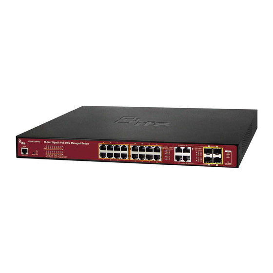
2.1.1 Switch Front Panel The front panel provides a simple interface monitoring of the Managed Switch. Figure 2-1-1 show the front panel of the Managed Switch. Figure 2-1-1 NS3503-16P-4C Front Panel Gigabit TP Interface 10/100/1000BASE-T copper, RJ45 twisted-pair: Up to 100 meters. -
Page 24: Led Indications
The front panel LEDs indicates instant status of port links, data activity and system power; it helps monitor and troubleshoot when needed. Figure 2-1-2 shows the LED indications of these Managed Switches. Figure 2-1-2 NS3503-16P-4C LED indication System / Alert... -
Page 25: Switch Rear Panel
The rear panel of the Managed Switch indicates an AC inlet power socket, which accepts input power from 100 to 240V AC, 50-60Hz. Figures 2-1-3 show the rear panel of these Managed Switches Figure 2-1-3 Rear Panel of NS3503-16P-4C ... -
Page 26: Installing The Switch
Note: When choosing a location, please keep in mind the environmental restrictions discussed in Chapter 1, Section 4, and specifications. 4. Connect the Managed Switch to network devices. Connect one end of a standard network cable to the 10/100/1000 RJ45 ports on the front of the Managed Switch. NS3503-16P-4C User Manual... -
Page 27: Rack Mounting
4. Follow the same steps to attach the second bracket to the opposite side. 5. After the brackets are attached to the Managed Switch, use suitable screws to securely attach the brackets to the rack, as shown in Figure 2-1-6. NS3503-16P-4C User Manual... -
Page 28: Installing The Sfp Transceiver
Figure 2-1-7 Plug in the SFP transceiver Approved IFS SFP Transceivers IFS Managed Switch supports both single mode and multi-mode SFP transceivers. The following list of approved IFS SFP transceivers is correct at the time of publication: NS3503-16P-4C User Manual... - Page 29 To connect to 1000BASE-SX SFP transceiver, please use the multi-mode fiber cable with one side being the male duplex LC connector type. To connect to 1000BASE-LX SFP transceiver, please use the single-mode fiber cable with one side being the male duplex LC connector type. NS3503-16P-4C User Manual...
- Page 30 Note: Never pull out the module without lifting up the lever of the module and turning it into a horizontal position. Directly pulling out the module could damage the module and the SFP module slot of the Managed Switch. NS3503-16P-4C User Manual...
-
Page 31: Switch Management
An external SNMP-based network management application The administration console and Web browser interfaces are embedded in the Managed Switch software and are available for immediate use. Each of these management methods has their own advantages. Table 3-1 compares the three management methods. NS3503-16P-4C User Manual... -
Page 32: Administration Console
Direct access to the administration console is achieved by directly connecting a terminal or a PC equipped with a terminal-emulation program (such as HyperTerminal) to the Managed Switch console (serial) port. When using this management method, a straight RS-232 to RJ45 cable is required to NS3503-16P-4C User Manual... -
Page 33: Web Management
Microsoft Internet Explorer. After you set up your IP address for the switch, you can access the Managed Switch's Web interface applications directly in your Web browser by entering the IP address of the Managed Switch. NS3503-16P-4C User Manual... -
Page 34: Snmp-Based Network Management
Station only knows the set community string, it can read and write to the MIBs. However, if it only knows the get community string, it can only read MIBs. The default gets and sets community strings for the Managed Switch are public. NS3503-16P-4C User Manual... -
Page 35: Ifs Smart Discovery Utility
Note: If there are two LAN cards or above in the same administrator PC, choose a different LAN card by using the “Select Adapter” tool. 3. Press “Refresh” button for the currently connected devices in the discovery list as the screen shows below: Figure 3-1-7: IFS Smart Discovery Utility Screen NS3503-16P-4C User Manual... - Page 36 6. Clickg the “Control Packet Force Broadcast” function to assign a new setting value to the Web Smart Switch under a different IP subnet address. 7. Press the “Connect to Device” button and the Web login screen appears in Figure 3-1-4. 8. Press the “Exit” button to shut down the IFS Smart Discovery Utility. NS3503-16P-4C User Manual...
-
Page 37: Web Configuration
2. When the following login screen appears, please enter the default username "admin" with password “admin” (or the username/password you have changed via console) to login the main screen of Managed Switch. The login screen in Figure 4-1-2 appears. NS3503-16P-4C User Manual... - Page 38 The changed IP address takes effect immediately after clicking on the Save button. You need to use the new IP address to access the Web interface. Note: For security reason, please change and memorize the new password after this first setup. NS3503-16P-4C User Manual...
-
Page 39: Main Web Page
RJ45 Ports SFP Ports PoE Ports Main Menu Using the onboard Web agent, you can define system parameters, manage and control the Managed Switch, and all its ports, or monitor network conditions. Via the Web-Management, the administrator can NS3503-16P-4C User Manual... -
Page 40: Save Button
This save button allows you to save the running / startup / backup configuration or reset switch in default parameter. If you forgot to save configuration, all configurations will be lost after system reboot. The screen in Figure 4-1-6 appears. NS3503-16P-4C User Manual... -
Page 41: Configuration Manager
To prevent illicit file upload and easier configuration, switch mandates the name of running configuration file to be running-config. Startup Configuration Refers to the configuration sequence used in switch startup. Startup configuration file stores in nonvolatile storage, corresponding to the NS3503-16P-4C User Manual... -
Page 42: Saving Configuration
1. Click ”Save > Save Configurations to FLASH” to login “Configuration Manager” page. 2. Select “Source File = Running Configuration” and “Destination File = Startup Configuration”. 3. Press the “Apply” button to save running configuration to startup configuration. NS3503-16P-4C User Manual... -
Page 43: System
The System Info page provides information for the current device information. System Info page helps a switch administrator to identify the hardware MAC address, software version and system uptime. The screens in Figures 4-2-1 and 4-2-2 appear. Figure 4-2-1 System Information Page Screenshot NS3503-16P-4C User Manual... -
Page 44: Ip Configurations
The IP Configuration includes the IP Address, Subnet Mask and Gateway. The configured column is used to view or change the IP configuration. Fill out the IP Address, Subnet Mask and Gateway for the device. The screens in Figure 4-2-2 and Figure 4-2-3 appear. Figure 4-2-2 IP Address Setting Page Screenshot NS3503-16P-4C User Manual... - Page 45 Figure 4-2-3 IP Information Page Screenshot The page includes the following fields: Object Description DHCP State Display the current DHCP state. IP Address Display the current IP address. Subnet Mask Display the current subnet mask. Gateway Display the current gateway. NS3503-16P-4C User Manual...
-
Page 46: Ipv6 Configuration
To enable this Managed Switch to accept a configuration from a Dynamic Host Configuration Protocol version 6 (DHCPv6) server. By default, the Managed Switch does not perform DHCPv6 client actions. DHCPv6 clients request the delegation of long-lived prefixes that they can push to individual local hosts. NS3503-16P-4C User Manual... -
Page 47: User Configuration
“Apply” button to take effect. Please login Web interface with a new user name and password; the screens in Figure 4-2-6 and Figure 4-2-7 appear. Figure 4-2-6 Local User Information Page Screenshot The page includes the following fields: NS3503-16P-4C User Manual... - Page 48 The page includes the following fields: Object Description Username Display the current username Password Type Display the current password type Privilege Type Display the current privilege type Modify Click to modify the local user entry : Delete the current user NS3503-16P-4C User Manual...
-
Page 49: Time Settings
Daylight Saving Time duration. Select 'Disable' to disable the Daylight Saving Time configuration. Select 'Recurring' and configure the Daylight Saving Time duration to repeat the configuration every year. Select 'Non-Recurring' and configure the Daylight Saving Time NS3503-16P-4C User Manual... - Page 50 Week - Select the starting week number. Day - Select the starting day. Month - Select the starting month. Hours - Select the starting hour. Minutes - Select the starting minute. Buttons : Click to apply changes. NS3503-16P-4C User Manual...
-
Page 51: Sntp Server Settings
From Display the current daylight saving time from Display the current daylight saving time to 4.2.5.2 SNTP Server Settings The SNTP Server Configuration screens in Figure 4-2-10 and Figure 4-2-11 appear. Figure 4-2-10 SNTP Setup Page Screenshot NS3503-16P-4C User Manual... -
Page 52: Log Management
Normal but significant condition, such as cold start Warning Warning conditions (e.g., return false, unexpected return) Error Error conditions (e.g., invalid input, default used) Critical Critical conditions (e.g., memory allocation, or free memory error - resource exhausted) NS3503-16P-4C User Manual... -
Page 53: Local Log
The page includes the following fields: Object Description Logging Service Display the current logging service status 4.2.6.2 Local Log The switch system local log information is provided here. The local Log screens in Figures 4-2-14 and 4-2-15 appear. NS3503-16P-4C User Manual... - Page 54 Figure 4-2-15 Local Log Setting Status Page Screenshot The page includes the following fields: Object Description Status Display the current local log state Target Display the current local log target Severity Display the current local log severity Action : Delete the current status NS3503-16P-4C User Manual...
-
Page 55: Remote Syslog
Error level of the error conditions for local log. warning: Warning level of the warning conditions for local log. notice: Notice level of the normal but significant conditions for local log. info: Informational level of the informational messages for local log. NS3503-16P-4C User Manual... -
Page 56: Log Message
The switch log view is provided here. The Log View screens in Figure 4-2-18, Figure 4-2-19 and Figure 4-2-20 appear. Figure 4-2-18 Log Information Select Page Screenshot The page includes the following fields: Object Description Target The target of the log view entry. The following target types are supported: NS3503-16P-4C User Manual... - Page 57 Figure 4-2-19 Logging Information Page Screenshot The page includes the following fields: Object Description Target Display the current log target Severity Display the current log severity Category Display the current log category Total Entries Display the current log entries NS3503-16P-4C User Manual...
-
Page 58: Snmp Management
At least one NMS must be present in each managed environment. AgentsAgents are software modules that reside in network elements. They collect and store management information such as the number of error packets received by a network element. NS3503-16P-4C User Manual... -
Page 59: Snmp System Information
Figure 4-2-21 SNMP Global Setting Page Screenshot The page includes the following fields: Object Description Status Indicates the SNMP mode operation. Possible modes are: Enabled: Enable SNMP mode operation. Disabled: Disable SNMP mode operation. Buttons : Click to apply changes. NS3503-16P-4C User Manual... -
Page 60: Snmp View
An optional flag to indicate that this view subtree should be excluded. General, if a view entry's view type is 'excluded', it should exist another view entry in which view type is 'included' and its OID subtree oversteps the 'excluded' view entry. NS3503-16P-4C User Manual... -
Page 61: Snmp Access Group
A string identifying the group name to which this entry should belong. The allowed string length is 1 to 16. Security Model Indicates the security model to whichthis entry should belong. Possible security models are: v1: Reserved for SNMPv1. NS3503-16P-4C User Manual... - Page 62 Display the current security model Security Level Display the current security level Read View Name Display the current read view name Write View Name Display the current write view name Notify View Name Display the current notify view name NS3503-16P-4C User Manual...
-
Page 63: Snmp Community
Indicates the SNMP community type operation. Possible types are: RO=Read-Only: Set access string type in read-only mode. RW=Read-Write: Set access string type in read-write mode. Buttons : Click to apply changes. Figure 4-2-28 Community Status Page Screenshot NS3503-16P-4C User Manual... -
Page 64: Snmp User
MD5: An optional flag to indicate that this user using MD5 authentication protocol. SHA: An optional flag to indicate that this user using SHA authentication protocol. The value of security level cannot be modified if entry already exists. That NS3503-16P-4C User Manual... - Page 65 Display the current group Privilege Mode Display the current privilege mode Authentication Protocol Display the current authentication protocol Encryption Protocol Display the current encryption protocol Access Right Display the current access right Action : Delete the user entry NS3503-16P-4C User Manual...
-
Page 66: Snmpv1, 2 Notification Recipients
Indicates the SNMP trap inform timeout. The allowed range is 1 to 300. Retries Indicates the SNMP trap inform retry times. The allowed range is 1 to 255. Buttons : Click to add a new SNMPv1, 2 host entry. Figure 4-2-32 SNMPv1, 2 Host Status Page Screenshot NS3503-16P-4C User Manual... -
Page 67: Snmpv3 Notification Recipients
1~65535. Time Out Indicates the SNMP trap inform timeout. The allowed range is 1 to 300. Retries Indicates the SNMP trap inform retry times. The allowed range is 1 to 255. NS3503-16P-4C User Manual... -
Page 68: Snmp Engine Id
The SNMPv3 Engine ID Setting screens in Figure 4-2-35 and Figure 4-2-36 appear. Figure 4-2-35 SNMPv3 Engine ID Setting Page Screenshot NS3503-16P-4C User Manual... -
Page 69: Snmp Remote Engine Id
Figure 4-2-37 SNMPv3 Remote Engine ID Setting Page Screenshot The page includes the following fields: Object Description Remote IP Address Indicates the SNMP remote engine ID address. It allows a valid IP address in dotted decimal notation ('x.y.z.w'). NS3503-16P-4C User Manual... -
Page 70: Port Management
Sets the jumbo frame on the switch Port Error Disable Configuration Configures port error disable settings Port Error Disabled Status Disables port error status Protected Ports Configures protected ports settings SFP Module Information Displays SFP module information. NS3503-16P-4C User Manual... -
Page 71: Port Configuration
The Rx and Tx settings are determined by the result of the last Auto-Negotiation. Check the configured column to use flow control. This setting is related to the setting for Configured Link Speed. NS3503-16P-4C User Manual... -
Page 72: Port Counters
4.3.2 Port Counters This page provides an overview of traffic and trunk statistics for all switch ports. The Port Statistics screens in Figure 4-3-3, Figure 4-3-4, Figure 4-3-5 and Figure 4-3-6 appear. Figure 4-3-3 Port MIB Counters Page Screenshot NS3503-16P-4C User Manual... - Page 73 The total number of packets that higher-level protocols requested is transmitted to a subnetwork-unicast address, including those that were discarded or not sent. Transmit Unknown Unicast The total number of packets that higher-level protocols requested is Packets transmitted to a subnetwork-unicast address, including those that were NS3503-16P-4C User Manual...
- Page 74 A count of frames for which the first transmission attempt on a particular interface is delayed because the medium was busy. Late Collision The number of times that a collision is detected later than 512 bit-times into the transmission of a packet. NS3503-16P-4C User Manual...
- Page 75 The total number of good frames received that were directed to the broadcast address. Note that this does not include multicast packets. Multicast Packets The total number of good frames received that were directed to this multicast address. NS3503-16P-4C User Manual...
-
Page 76: Bandwidth Utilization
Bandwidth utilization statistics can be viewed using a line graph. The Bandwidth Utilization screen in Figure 4-3-7 appears. To view the port utilization, click on the Port Management folder and then the Bandwidth Utilization link: NS3503-16P-4C User Manual... -
Page 77: Port Mirroring
The Managed Switch can unobtrusively mirror traffic from any port to a monitor port. You can then attach a protocol analyzer or RMON probe to this port to perform traffic analysis and verify connection integrity. NS3503-16P-4C User Manual... - Page 78 Monitor Session State Enable or disable the port mirroring function. Destination Port Select the port to mirror destination port. Allow-ingress Frames from ports that have either source (rx) or destination (tx) mirroring enabled are mirrored to this port. NS3503-16P-4C User Manual...
-
Page 79: Jumbo Frame
Display the current RX ports 4.3.5 Jumbo Frame This page provides to select the maximum frame size allowed for the switch port. The Jumbo Frame screen in Figure 4-3-11 and Figure 4-3-12 appear. Figure 4-3-11 Jumbo Frame Setting Page Screenshot NS3503-16P-4C User Manual... - Page 80 Enter the maximum frame size allowed for the switch port, including FCS. The allowed range is 64 bytes to 9216 bytes. Buttons : Click to apply changes. Figure 4-3-12 Jumbo Frame Information Page Screenshot The page includes the following fields: Object Description Jumbo Display the current maximum frame size NS3503-16P-4C User Manual...
-
Page 81: Port Error Disabled Configuration
Enable or disable the port error disabled function to check status by DHCP rate limit ARP Rate Limit Enable or disable the port error disabled function to check status by ARP rate limit Buttons : Click to apply changes. NS3503-16P-4C User Manual... - Page 82 Display the current unicast flood status Display the current ACL status Port Security Violation Display the current port security violation status DHCP Rate Limit Display the current DHCP rate limit status ARP Rate Limit Display the current ARP rate limit status NS3503-16P-4C User Manual...
-
Page 83: Port Error Disabled
Servers in a farm of web servers in a Demilitarized Zone (DMZ) are allowed to communicate with the outside world and with database servers on the inside segment, but are not allowed to communicate with each other NS3503-16P-4C User Manual... - Page 84 VLAN table. This reduces the ports to which forwarding can be done to just the promiscuous ports within the private VLAN. The port settings relate to the currently unit, as reflected by the page header. The Port Isolation Configuration screens in Figure 4-3-16 and Figure 4-3-17 appear. NS3503-16P-4C User Manual...
- Page 85 VLAN. This is the default setting. Buttons : Click to apply changes. Figure 4-3-17 Port Isolation Status Page Screenshot The page includes the following fields: Object Description Protected Ports Display the current protected ports Unprotected Ports Display the current unprotected ports NS3503-16P-4C User Manual...
-
Page 86: Link Aggregation
Link Aggregation Control Protocol (LACP) LAGs - LACP LAG negotiate Aggregated Port links with other LACP ports located on a different device. If the other device ports are also LACP ports, the devices establish a LAG between them. Figure 4-4-1 Link Aggregation NS3503-16P-4C User Manual... - Page 87 Configures load balance algorithm configuration settings LAG Management Configures LAG configuration settings LAG Port Setting Configures LAG port settings LACP Setting Configures LACP priority settings LACP Port Setting Configure LACP configuration settings LAG Status Display LAG status / LACP information NS3503-16P-4C User Manual...
-
Page 88: Lag Setting
IP/MAC Address: The IP and MAC address can be used to calculate the port for the frame. Buttons : Click to apply changes. Figure 4-4-3 LAG Information Page Screenshot The page includes the following fields: Object Description Load Balance Algorithm Display the current load balance algorithn NS3503-16P-4C User Manual... -
Page 89: Lag Management
If the other device ports are also LACP ports, the devices establish a LAG between them. Ports Select port number for this drop down list to establish Link Aggregation Figure 4-4-5 LAG Management Information Page Screenshot NS3503-16P-4C User Manual... -
Page 90: Lag Port Setting
Auto – Set up Auto negotiation. Auto-10M – Set up 10M Auto negotiation. Auto-100M – Set up 100M Auto negotiation. Auto-1000M - Set up 1000M Auto negotiation. Auto-10/100M – Set up 10/100M Auto negotiation. NS3503-16P-4C User Manual... - Page 91 Display the current port type Enable State Display the current enable state Speed Display the current speed Duplex Display the current duplex mode Flow Control Config Display the current flow control configuration Flow Control Status Display the current flow control status NS3503-16P-4C User Manual...
-
Page 92: Lacp Setting
LACP peer of the trunk group. Buttons : Click to apply changes. Figure 4-4-9 LACP Information Page Screenshot The page includes the following fields: Object Description System Priority Display the current system priority. NS3503-16P-4C User Manual... -
Page 93: Lacp Port Setting
The Timeout controls the period between BPDU transmissions. Short will transmit LACP packets each second, while Long will wait for 30 seconds before sending an LACP packet. Buttons : Click to apply changes. Figure 4-4-11 LACP Port Information Page Screenshot NS3503-16P-4C User Manual... -
Page 94: Lag Status
Display the current LAG name Type Display the current trunk type Link State Display the current link state Active Member Display the current active member Standby Member Display the current standby member Figure 4-4-13 LACP Information Page Screenshot NS3503-16P-4C User Manual... - Page 95 The contents could be true or false. If the contents are false, the web will show “_”; if the contents are true, the Web shows “A”, “T”, “G”, “S”, “C”, “D”, “F” and “E” for each content respectively. NS3503-16P-4C User Manual...
-
Page 96: Vlan
The Managed Switch's default is to assign all ports to a single 802.1Q VLAN named DEFAULT_VLAN. As new VLAN is created, the member ports assigned to the new VLAN will be removed from the DEFAULT_ VLAN port member list. The DEFAULT_VLAN has a VID = 1. NS3503-16P-4C User Manual... -
Page 97: Ieee 802.1Q Vlan
Up to 255 VLANs based on the IEEE 802.1Q standard Port overlapping, allowing a port to participate in multiple VLANs End stations can belong to multiple VLANs Passing traffic between VLAN-aware and VLAN-unaware devices NS3503-16P-4C User Manual... - Page 98 1 bits 12 bits TPID (Tag Protocol Identifier) TCI (Tag Control Information) 2 bytes 2 bytes Destination Source Ethernet Preamble VLAN TAG Data Address Address Type 6 bytes 6 bytes 4 bytes 2 bytes 46-1500 bytes 4 bytes NS3503-16P-4C User Manual...
- Page 99 The Switch initially configures one VLAN, VID = 1, called "default." The factory default setting assigns all ports on the Switch to the "default". As new VLAN are configured in Port-based mode, their respective member ports are removed from the "default." NS3503-16P-4C User Manual...
-
Page 100: Management Vlan
Configure Management VLAN on this page. The screens in Figure 4-5-1 and Figure 4-5-2 appear. Figure 4-5-1 Management VLAN Setting Page Screenshot The page includes the following fields: Object Description Management VLAN Provide the managed VLAN ID NS3503-16P-4C User Manual... -
Page 101: Create Vlan
VLAN List Indicates the ID of this particular VLAN. VLAN Action This column allows users to add or delete VLAN s. VLAN Name Prefix Indicates the name of this particular VLAN. Buttons : Click to apply changes. NS3503-16P-4C User Manual... -
Page 102: Interface Settings
802.1Q VLAN information. (Remember that the PVID is only used internally within the Switch). Untagging is used to send packets from an 802.1Q-compliant network device to a non-compliant network device. NS3503-16P-4C User Manual... - Page 103 VLANs in the MAN space can be used independent of the customers’ VLANs. This is accomplished by adding a VLAN tag with a MAN-related VID for frames entering the MAN. When leaving the MAN, the tag is stripped and the original VLAN tag with the customer-related VID is again available. NS3503-16P-4C User Manual...
- Page 104 If ingress filtering is disabled, frames classified to a VLAN that the port is not a member of are accepted and forwarded to the switch engine. However, the port will never transmit frames classified to VLANs that it is not a member of. NS3503-16P-4C User Manual...
- Page 105 Display the current interface VLAN mode PVID Display the current PVID Accepted Frame Type Display the current access frame type Ingress Filtering Display the current ingress filtering Uplink Display the current uplink mode TPID Display the current TPID NS3503-16P-4C User Manual...
-
Page 106: Port To Vlan
VLAN or CoS information. Note that an interface must be assigned to at least one group as an untagged port. PVID Display the current PVID NS3503-16P-4C User Manual... -
Page 107: Port Vlan Membership
VLAN groups for each required protocol. When a frame is received at a port, its VLAN membership can then be determined based on the protocol type being used by the inbound packets. NS3503-16P-4C User Manual... - Page 108 Valid value that can be entered in this text field depends on the option selected (0x0600-0xFFFE) from the preceding Frame Type selection menu. Valid values for frame type ranges from 0x0600-0xfffe Buttons : Click to apply changes. NS3503-16P-4C User Manual...
-
Page 109: Protocol Vlan Port Setting
Description Port Select port for this drop down list to assign protocol VLAN port Group Select group ID for this drop down list to protocol VLAN group VLAN VLAN ID assigned to the Special Protocol VLAN Group NS3503-16P-4C User Manual... - Page 110 Figure 4-5-12 Protocol VLAN Port State Page Screenshot The page includes the following fields: Object Description Port Display the current port Group ID Display the current group ID VLAN ID Display the current VLAN ID Delete Click to delete the group ID entry NS3503-16P-4C User Manual...
-
Page 111: Gvrp Setting
GVRP must be enabled to permit automatic VLAN registration, and to support VLANs which extend beyond the local switch. The GVRP Global Setting/Information screens in Figure 4-5-13 and Figure 4-5-14 appear. Figure 4-5-13 GVRP Global Setting Page Screenshot NS3503-16P-4C User Manual... - Page 112 2 x (join timer) < leave timer < leaveAll timer Buttons : Click to apply changes. Figure 4-5-14 GVRP Global Setting Page Screenshot The page includes the following fields: Object Description GVRP Status Display the current GVRP status NS3503-16P-4C User Manual...
-
Page 113: Gvrp Port Setting
GVRP can dynamically create VLANs on switches for trunking purposes. By enabling GVRP dynamic VLAN creation, a switch will add VLANs to its database when it receives GVRP join messages about VLANs it does not have. Buttons : Click to apply changes. NS3503-16P-4C User Manual... -
Page 114: Gvrp Vlan
Figure 4-5-17 GVRP VLAN Database Status Page Screenshot The page includes the following fields: Object Description VLAN ID Display the current VLAN ID Member Ports Display the current member ports Dynamic Ports Display the current dynamic ports VLAN Type Display the current VLAN type NS3503-16P-4C User Manual... -
Page 115: Gvrp Statistics
Display the current leave in (TX/RX) packets LeaveAll (Rx/Tx) Display the current leaveall (TX/RX) packets Figure 4-5-19 GVRP Port Error Statistics Page Screenshot The page includes the following fields: Object Description Port The switch port number of the logical port. NS3503-16P-4C User Manual... -
Page 116: Vlan Setting Example
VLAN Group 2 and VLAN Group 3 are separated VLANs. Each VLAN isolates network traffic so only members of the VLAN receive traffic from the same VLAN members. The screen in Figure 4-5-20 appears and Table 4-5-2 describes the port configuration of the Managed Switches. NS3503-16P-4C User Manual... - Page 117 1. While [PC-3] transmits a tagged packet with VLAN Tag=2 enters Port-3, [PC-1] and [PC-2] will receive the packet through Port-1 and Port-2. 2. While the packet leaves Port-1 and Port-2, it will be stripped away its tag becoming an untagged packet. NS3503-16P-4C User Manual...
- Page 118 2. Assign VLAN mode and PVID to each port: Port-1,Port-2 and Port-3 : VLAN Mode = Hybrid, PVID=2 Port-4,Port-5 and Port-6 : VLAN Mode = Hybrid, PVID=3 3. Assign Tagged/Untagged to each port: VLAN ID = 2: Port-1 & 2 = Untagged, NS3503-16P-4C User Manual...
-
Page 119: Vlan Trunking Between Two 802.1Q Aware Switches
4.5.14.2 VLAN Trunking between two 802.1Q aware switches In most cases, they are used for “Uplink” to other switches. VLANs are separated at different switches, but they need to access other switches within the same VLAN group. The screen in Figure 4-5-21 appears. NS3503-16P-4C User Manual... - Page 120 Add VLAN group 2 and group 3 2. Assign VLAN mode and PVID to each port: Port-1,Port-2 and Port-3 : VLAN Mode = Hybrid, PVID=2 Port-4,Port-5 and Port-6 : VLAN Mode = Hybrid, PVID=3 Port-7 : VLAN Mode = Hybrid, PVID=1 NS3503-16P-4C User Manual...
- Page 121 VLAN ID = 1: Port-1~6 = Untagged, Port -7 = Excluded. VLAN ID = 2: Port-1 & 2 = Untagged, Port-3 & 7 = Tagged, Port -4~6 = Excluded. VLAN ID = 3: Port-4 & 5 = Untagged, NS3503-16P-4C User Manual...
-
Page 122: Spanning Tree Protocol
The Switch STP performs the following functions: Creates a single spanning tree from any combination of switching or bridging elements. Creates multiple spanning trees – from any combination of ports contained within a single switch, in user specified groups. NS3503-16P-4C User Manual... - Page 123 Blocking state to a Forwarding state could create temporary data loops. Ports must wait for new network topology information to propagate throughout the network before starting to forward packets. They must also wait for the packet lifetime to expire for NS3503-16P-4C User Manual...
- Page 124 Figure 4-6-1 STP Port State Transitions You can modify each port state by using management software. When you enable STP, every port on every switch in the network goes through the blocking state and then transitions through the states of NS3503-16P-4C User Manual...
- Page 125 Port Cost A value used by STP to evaluate paths – 200,000-100Mbps Fast Ethernet ports STP calculates path costs and selects the 20,000-1000Mbps Gigabit Ethernet path with the minimum cost as the active ports path 0 - Auto NS3503-16P-4C User Manual...
- Page 126 If switch A broadcasts a packet to switch B, switch B will broadcast it to switch C, and switch C will broadcast it to back to switch A and so on. The broadcast packet will be passed indefinitely in a loop, potentially causing a network failure. In this example, STP breaks the loop by blocking the connection NS3503-16P-4C User Manual...
- Page 127 Priority setting, or influencing STP to choose a particular port to block using the Port Priority and Port Cost settings is, however, relatively straight forward. Figure 4-6-2 Before Applying the STA Rules In this example, only the default STP values are used. NS3503-16P-4C User Manual...
- Page 128 Configuration per port STP setting CIST Instance Setting Configure system configuration CIST Port Setting Configure CIST port setting MST Instance Setting Configuration each MST instance setting MST Port Setting Configuration per port MST setting STP Statistics Display the STP statistics NS3503-16P-4C User Manual...
-
Page 129: Stp Global Settings
RSTP-Operation and MSTP-Operation. Configuration Name Identifier used to identify the configuration currently being used. Configuration Revision Identifier used to identify the configuration currently being used. The values allowed are between 0 and 65535. The default value is 0. NS3503-16P-4C User Manual... -
Page 130: Stp Port Setting
Display the current configuration name • Configuration Revision Display the current configuration revision 4.6.3 STP Port Setting This page allows you to configure per port STP settings. The STP Port Setting screens in Figure 4-6-6 and Figure 4-6-7 appear. NS3503-16P-4C User Manual... - Page 131 : Click to apply changes. By default, the system automatically detects the speed and duplex mode used on each port, and configures the path cost according to the values shown below. Path cost “0” is used to indicate NS3503-16P-4C User Manual...
- Page 132 Link Type IEEE 802.1w-2001 Ethernet Half Duplex 2,000,000 Full Duplex 1,000,000 Trunk 500,000 Fast Ethernet Half Duplex 200,000 Full Duplex 100,000 Trunk 50,000 Gigabit Ethernet Full Duplex 10,000 Trunk 5,000 Figure 4-6-7 STP Port Status Page Screenshot NS3503-16P-4C User Manual...
-
Page 133: Cist Instance Setting
BPDU information. Valid values are in the range 6 to 40 hops. Forward Delay The delay used by STP Bridges to transition Root and Designated Ports to Forwarding (used in STP compatible mode). Valid values are in the range 4 to NS3503-16P-4C User Manual... - Page 134 Object Description Priority Display the current CIST priority Max Hop Display the current Max. hop Forward Delay Display the current forward delay Max Age Display the current Max.Age Tx Hold Count Display the current Tx hold count NS3503-16P-4C User Manual...
-
Page 135: Cist Port Setting
The path cost is used when establishing the active topology of the network. Lower path cost ports are chosen as forwarding ports in favor of higher path cost ports. Valid values are in the range 1 to 200000000. Buttons : Click to apply changes. NS3503-16P-4C User Manual... - Page 136 Display the current internal port path cost Edge Port Conf/Oper Display the current edge port conf/oper P2P MAC Conf/Oper Display the current P2P MAC conf/oper Port Role Display the current port role Port State Display the current port state NS3503-16P-4C User Manual...
-
Page 137: Mst Instance Configuration
The page includes the following fields: Object Description MSTI Display the current MSTI entry Status Display the current MSTI status VLAN List Display the current VLAN list VLAN Count Display the current VLAN count Priority Display the current MSTI priority NS3503-16P-4C User Manual... -
Page 138: Mst Port Setting
MSTI instance configured and applicable for the port. The MSTI instance must be selected before displaying actual MSTI port configuration options. This page contains MSTI port settings for physical and aggregated ports. The aggregation settings are global. The MSTI Ports Setting screens in Figure 4-6-15 and Figure 4-6-16 appear. NS3503-16P-4C User Manual... - Page 139 Lower path cost ports are chosen as forwarding ports in favor of higher path cost ports. Valid values are in the range 1 to 200000000. Buttons : Click to apply changes. Figure 4-6-16 MST Port Status Page Screenshot The page includes the following fields: NS3503-16P-4C User Manual...
-
Page 140: Stp Statistics
• Configuration BPDUs Received Display the current configuration BPDUs received • TCN BPDUs Received Display the current TCN BPDUs received • MSTP BPDUs Received Display the current MSTP BPDUs received • Configuration BPDUs Display the configuration BPDUs transmitted NS3503-16P-4C User Manual... -
Page 141: Multicast
The page includes the following fields: Object Description Unknown Multicast Action Unknown multicast traffic method: Drop, flood or send to router port. IPv4 Forward Method Configure the IPv4 multicast forward method IPv6 Forward Method Configure the IPv6 multicast forward method NS3503-16P-4C User Manual... -
Page 142: Igmp Snooping
IGMP, to see if there is at least one member of a multicast group on a given subnet work. If there are no members on a sub network, packets will not be forwarded to that sub network. NS3503-16P-4C User Manual... - Page 143 Figure 4-7-3 Multicast Service Figure 4-7-4 Multicast Flooding NS3503-16P-4C User Manual...
- Page 144 Response Time Group Address (all zeros if this is a query) The IGMP Type codes are shown below: Type Meaning 0x11 Membership Query (if Group Address is 0.0.0.0) Specific Group Membership Query (if Group Address is 0x11 Present) NS3503-16P-4C User Manual...
- Page 145 IGMP Querier – A router, or multicast-enabled switch, can periodically ask their hosts if they want to receive multicast traffic. If there is more than one router/switch on the LAN performing IP multicasting, one of these NS3503-16P-4C User Manual...
-
Page 146: Igmp Setting
IGMP Snooping Report Limits the membership report traffic sent to multicast-capable routers. Suppression When you disable report suppression, all IGMP reports are sent as is to multicast-capable routers. The default is enabled. Buttons : Click to apply changes. NS3503-16P-4C User Manual... - Page 147 Display the current query max response interval (sec.) Last Member Query count Display the current last member query count Last Member Query Interval Display the current last member query interval (sec) Immediate Leave Display the current immediate leave NS3503-16P-4C User Manual...
-
Page 148: Igmp Querier Setting
Sets the querier version for compatibility with other devices on the network. Version: 2 or 3; Default: 2 Buttons : Click to apply changes. Figure 4-7-11 IGMP Querier Status Page Screenshot The page includes the following fields: NS3503-16P-4C User Manual... -
Page 149: Igmp Static Group
Select VLAN ID for this drop down list Group IP Address The IP address for a specific multicast service Member Ports Select port number for this drop down list Buttons : Click to add IGMP router port entry. NS3503-16P-4C User Manual... -
Page 150: Igmp Group Table
Depending on your network connections, IGMP snooping may not always be able to locate the IGMP querier. Therefore, if the IGMP querier is a known multicast router/ switch connected over the network to an interface (port or trunk) on your Managed Switch, you can manually configure the interface (and a NS3503-16P-4C User Manual... - Page 151 : Click to add IGMP router port entry. Figure 4-7-16 Router Port Status Page Screenshot The page includes the following fields: Object Description VLAN ID Display the current VLAN ID Static Ports Display the current static ports Forbidden Ports Display the current forbidden ports NS3503-16P-4C User Manual...
-
Page 152: Igmp Router Table
Expiry Time (Sec) Display the current expiry time Figure 4-7-18 Static Router Table Page Screenshot The page includes the following fields: Object Description VLAN ID Display the current VLAN ID Port Mask Display the current port mask NS3503-16P-4C User Manual... -
Page 153: Igmp Forward All
Select VLAN ID for this drop down list to assign IGMP membership Port The switch port number of the logical port Membership Select IGMP membership for each interface: Forbidden: Interface is forbidden from automatically joining the IGMP via MVR. NS3503-16P-4C User Manual... -
Page 154: Igmp Snooping Statics
: Click to apply changes. 4.7.3 IGMP Snooping Statics This page provides IGMP Snooping Statics. The IGMP Snooping Statics screen in Figure 4-7-20 appears. Figure 4-7-20 Forward All Setting Page Screenshot The page includes the following fields: NS3503-16P-4C User Manual... -
Page 155: Mld Snooping
Most of the settings are global, whereas the Router Port configuration is related to the current unit, as reflected by the page header. The MLD Snooping Setting, Information and Table screens in Figure 4-7-21, Figure 4-7-22 & Figure 4-7-23 appear. NS3503-16P-4C User Manual... - Page 156 The page includes the following fields: Object Description MLD Snooping Status Display the current MLD snooping status MLD Snooping Version Display the current MLD snooping version MLD Snooping Report Display the current MLD snooping report suppression Suppression NS3503-16P-4C User Manual...
-
Page 157: Mld Static Group
Display the current immediate leave Modify Click to edit parameter 4.7.4.2 MLD Static Group The MLD Static Group configuration screens in Figure 4-7-24 and Figure 4-7-25 appear. Figure 4-7-24 Add MLD Static Group Page Screenshot The page includes the following fields: NS3503-16P-4C User Manual... -
Page 158: Mld Group Table
4.7.4.3 MLD Group Table This page provides MLD Group Table. The MLD Group Table screen in Figure 4-7-26 appears. Figure 4-7-26 MLD Group Table Page Screenshot The page includes the following fields: Object Description VLAN ID Display the current VID NS3503-16P-4C User Manual... -
Page 159: Mld Router Setting
Specify which ports act as router ports. A router port is a port on the Ethernet switch that leads towards the Layer 3 multicast device or MLD querier. Forbid Port Select Specify which ports un-act as router ports Buttons : Click to add MLD router port entry. NS3503-16P-4C User Manual... -
Page 160: Mld Router Table
Figure 4-7-29 Dynamic Router Table Page Screenshot The page includes the following fields: Object Description VLAN ID Display the current VLAN ID Port Display the current dynamic router ports Expiry Time (Sec) Display the current expiry time NS3503-16P-4C User Manual... -
Page 161: Mld Forward All
The page includes the following fields: Object Description VLAN ID Display the current VLAN ID Port Mask Display the current port mask 4.7.4.6 MLD Forward All This page provides MLD Forward All. The Forward All screen in Figure 4-7-32 appears. NS3503-16P-4C User Manual... -
Page 162: Mld Snooping Statics
VLAN will not be transmitted by the interface. Static: Interface is a member of the MLD. Buttons : Click to apply changes. 4.7.5 MLD Snooping Statics This page provides MLD Snooping Statics. The MLD Snooping Statics screen in Figure 4-7-33 appears. NS3503-16P-4C User Manual... - Page 163 Display current special group and source query RX Query RX Leave TX Display current leave TX Report TX Display current report TX General Query TX Display current general query TX Special Group Query TX Display current special group query TX NS3503-16P-4C User Manual...
-
Page 164: Multicast Throttling Setting
Sets the maximum number of multicast groups an interface can join at the same time. Range: 0-256; Default: 256 Action Sets the action to take when the maximum number of multicast groups for the interface has been exceeded. NS3503-16P-4C User Manual... -
Page 165: Multicast Filter
If a requested multicast group is denied, the multicast join report is dropped. When you have created a Multicast profile number, you can then configure the multicast groups to filter and set the access mode. Command Usage NS3503-16P-4C User Manual... -
Page 166: Multicast Profile Setting
- Deny When the access mode is set to, multicast join reports are only processed when the multicast group is not in the controlled range. Buttons : Click to add multicast profile entry. NS3503-16P-4C User Manual... -
Page 167: Igmp Filter Setting
The Filter Setting and Status screens in Figure 4-7-38 and Figure 4-7-39 appear. Figure 4-7-38 Filter Setting Page Screenshot The page includes the following fields: Object Description Port Select Select port number for this drop down list Filter Profile ID Select filter profile ID for this drop down list NS3503-16P-4C User Manual... -
Page 168: Mld Filter Setting
The Filter Setting and Status screens in Figure 4-7-40 and Figure 4-7-41 appear. Figure 4-7-40 Filter Setting Page Screenshot The page includes the following fields: Object Description Port Select Select port number for this drop down list Filter Profile ID Select filter profile ID for this drop down list NS3503-16P-4C User Manual... -
Page 169: Quality Of Service
Assigning priorities to traffic (for example, to set higher priorities to time-critical or business-critical applications). Applying security policy through traffic filtering. Provide predictable throughput for multimedia applications such as video conferencing or voice over IP by minimizing delay and jitter. NS3503-16P-4C User Manual... -
Page 170: General
8:1. 4.8.2 General 4.8.2.1 QoS Properties The QoS Global Setting and Information screen in Figure 4-8-1 and Figure 4-8-2 appear. Figure 4-8-1 QoS Global Setting Page Screenshot The page includes the following fields: NS3503-16P-4C User Manual... -
Page 171: Qos Port Settings
The QoS Port Settings and Status screens in Figure 4-8-2 and Figure 4-8-3 appear. Figure 4-8-2 QoS Port Setting Page Screenshot The page includes the following fields: Object Description Port Select Select port number for this drop down list CoS Value Select CoS value for this drop down list NS3503-16P-4C User Manual... -
Page 172: Queue Settings
Display the current remark CoS Remark DSCP Display the current remark DSCP Remark IP Precedence Display the current remark IP precedence 4.8.2.3 Queue Settings The Queue Table and Information screens in Figure 4-8-4 and Figure 4-8-5 appear. NS3503-16P-4C User Manual... - Page 173 Controls the weight for this queue. This value is restricted to 1-100. This parameter is only shown if "Scheduler Mode" is set to "Weighted". % of WRR Bandwidth Display the current bandwidth for each queue Buttons : Click to apply changes. Figure 4-8-5 Queue Information Page Screenshot NS3503-16P-4C User Manual...
-
Page 174: Cos Mapping
Figure 4-8-6 CoS to Queue and Queue to CoS Mapping Page Screenshot The page includes the following fields: Object Description Queue Select Queue value for this drop down list Class of Service Select CoS value for this drop down list Buttons : Click to apply changes. NS3503-16P-4C User Manual... -
Page 175: Dscp Mapping
Display the current mapping to queue Queue Display the current queue value Mapping to CoS Display the current mapping to CoS 4.8.2.5 DSCP Mapping The DSCP to Queue and Queue to DSCP Mapping screens in Figure 4-8-8 and Figure 4-8-9 appear. NS3503-16P-4C User Manual... - Page 176 The page includes the following fields: Object Description Queue Select Queue value for this drop down list DSCP Select DSCP value for this drop down list Buttons : Click to apply changes. Figure 4-8-9 DSCP Mapping Page Screenshot NS3503-16P-4C User Manual...
-
Page 177: Ip Precedence Mapping
The IP Precedence to Queue and Queue to IP Precedence Mapping screens in Figure 4-8-10 and Figure 4-8-11 appear. Figure 4-8-10 IP Precedence to Queue and Queue to IP Precedence Mapping Page Screenshot The page includes the following fields: NS3503-16P-4C User Manual... - Page 178 The page includes the following fields: Object Description IP Precedence Display the current CoS value Mapping to Queue Display the current mapping to queue Queue Display the current queue value Mapping to IP Precedence Display the current mapping to IP Precedence NS3503-16P-4C User Manual...
-
Page 179: Qos Basic Mode
Description Trust Mode Set the QoS mode Buttons : Click to apply changes. QoS Information Figure 4-8-13 QoS Information Page Screenshot The page includes the following fields: Object Description Trust Mode Display the current QoS mode NS3503-16P-4C User Manual... -
Page 180: Port Settings
Buttons : Click to apply changes. Figure 4-8-15 QoS Port Status Page Screenshot The page includes the following fields: Object Description Port The switch port number of the logical port Trust Mode Display the current trust type NS3503-16P-4C User Manual... -
Page 181: Rate Limit
: Click to apply changes. Figure 4-8-17 Ingress Bandwidth Control Status Page Screenshot The page includes the following fields: Object Description Port The switch port number of the logical port Ingress Rate Limit (Kbps) Display the current ingress rate limit NS3503-16P-4C User Manual... -
Page 182: Egress Bandwidth Control
: Click to apply changes. Figure 4-8-19 Egress Bandwidth Control Status Page Screenshot The page includes the following fields: Object Description Port The switch port number of the logical port Egress Rate Limit (Kbps) Display the current egress rate limit NS3503-16P-4C User Manual... -
Page 183: Egress Queue
0 to 1000000. Buttons : Click to apply changes. Figure 4-8-21 Egress Queue Status Page Screenshot The page includes the following fields: Object Description Queue ID Display the current queue ID Rate Limit (Kbps) Display the current rate limit NS3503-16P-4C User Manual... -
Page 184: Voice Vlan
Before connecting the IP device to the switch, the IP phone should configure the voice VLAN ID correctly. It should be configured through its own GUI. This page provides to select the ingress bandwidth preamble. The Ingress Bandwidth Control Setting/Status screen in Figure 4-8-22 and Figure 4-8-23 appears. NS3503-16P-4C User Manual... - Page 185 Enable or disable 802.1p remark Aging Time (30-65536 The time after which a port is removed from the Voice VLAN when VoIP traffic min) is no longer received on the port. (\Default: 1440 minutes). Buttons : Click to apply changes. NS3503-16P-4C User Manual...
-
Page 186: Telephony Oui Mac Setting
4.8.5.3 Telephony OUI MAC Setting Configure VOICE VLAN OUI table on this Page. The Telephony OUI MAC Setting screens in Figure 4-8-24 and Figure 4-8-25 appear. Figure 4-8-24 Voice VLAN OUI Settings Page Screenshot The page includes the following fields: NS3503-16P-4C User Manual... -
Page 187: Telephony Oui Port Setting
It is recommended that there be two VLANs on a port - one for voice, one for data. Before connecting the IP device to the switch, the IP phone should configure the voice VLAN ID NS3503-16P-4C User Manual... - Page 188 CoS Mode Select the current CoS mode Buttons : Click to apply changes. Figure 4-8-27 Voice VLAN Port State Page Screenshot The page includes the following fields: Object Description Port The switch port number of the logical port NS3503-16P-4C User Manual...
-
Page 189: Security
The switch simply encapsulates the EAP part of the frame into the relevant type (EAPOL or RADIUS) and forwards it. NS3503-16P-4C User Manual... -
Page 190: Understanding Ieee 802.1X Port-Based Authentication
This section includes this conceptual information: Device Roles Authentication Initiation and Message Exchange Ports in Authorized and Unauthorized States Device Roles With 802.1X port-based authentication, the devices in the network have specific roles as shown below. Figure 4-9-1 NS3503-16P-4C User Manual... - Page 191 When the client supplies its identity, the switch begins its role as the intermediary, passing EAP frames between the client and the authentication server until authentication succeeds or fails. If the authentication succeeds, the switch port becomes authorized. NS3503-16P-4C User Manual...
- Page 192 If the authentication fails, the port remains in the unauthorized state, but authentication can be retried. If the authentication server cannot be reached, the switch can retransmit the request. If no response is received from the server after the specified number of attempts, authentication fails, and network access is not granted. NS3503-16P-4C User Manual...
-
Page 193: Setting
Indicates if NAS is globally enabled or disabled on the switch. If globally disabled, all ports are allowed forwarding of frames. Buttons : Click to apply changes. Figure 4-9-4 802.1X Information Page Screenshot The page includes the following fields: NS3503-16P-4C User Manual... -
Page 194: Port Setting
If checked, successfully authenticated supplicants/clients are reauthenticated after the interval specified by the Reauthentication Period. Reauthentication for 802.1X-enabled ports can be used to detect if a new device is plugged into a switch port or if a supplicant is no longer attached. NS3503-16P-4C User Manual... - Page 195 Reauthentication Period Display the current reauthentication period. Quiet Period Display the current quiet period. Supplicant Timeout Display the current supplicant timeout. Max. EAP Requests Display the current Max. EAP requests. Modify Click to edit 802.1X port setting parameter. NS3503-16P-4C User Manual...
-
Page 196: Guest Vlan Setting
A Guest VLAN is a special VLAN - typically with limited network access - on which 802.1X-unaware clients are placed after a network administrator-defined timeout. The switch follows a set of rules for entering and leaving the Guest NS3503-16P-4C User Manual... -
Page 197: Authenticated Host
Description Port Name The switch port number of the logical port Enable State Display the current state In Guest VLAN Display the current guest VLAN 4.9.1.5 Authenticated Host The Authenticated Host Table screen in Figure 4-9-9 appears. NS3503-16P-4C User Manual... -
Page 198: Radius Server
Dead Time The Dead Time, which can be set to a number between 0 and 3600 seconds, is the period during which the switch will not send new requests to a server that NS3503-16P-4C User Manual... - Page 199 The Timeout, which can be set to a number between 1 and 30 seconds, is the maximum time to wait for a reply from a server. If the server does not reply within this timeframe, we will consider it to be dead NS3503-16P-4C User Manual...
- Page 200 Description IP Address Display the current IP address Auth Port Display the current auth port Acct Port Display the current acct port Display the current key Timeout Display the current timeout Retries Display the current retry times NS3503-16P-4C User Manual...
-
Page 201: Tacacs+ Server
Retransmit is the number of times, in the range 1 to 30, a TACACS+ request is retransmitted to a server that is not responding. If the server has not responded after the last retransmit it is considered to be dead. Buttons : Click to apply changes. NS3503-16P-4C User Manual... - Page 202 Set the server priority Buttons : Click to add Radius server setting. Figure 4-9-15 Login Authentication List Page Screenshot The page includes the following fields: Object Description IP Address Display the current IP address Port Display the current port NS3503-16P-4C User Manual...
-
Page 203: Aaa
Note: This guide assumes that RADIUS and TACACS+ servers have already been configured to support AAA. The configuration of RADIUS and TACACS+ server software is beyond the scope of this guide, refer to the documentation provided with the RADIUS or TACACS+ server software. NS3503-16P-4C User Manual... -
Page 204: Login List
The page includes the following fields: Object Description List Name Display the current list name Method List Display the current method list Modify Click to edit login authentication list parameter Click to delete login authentication list entry NS3503-16P-4C User Manual... -
Page 205: Enable List
The page includes the following fields: Object Description List Name Display the current list name Method List Display the current method list Modify Click to edit login authentication list parameter Click to delete login authentication list entry NS3503-16P-4C User Manual... -
Page 206: Access
Select enable authentication list for this drop down list Session Timeout Set the session timeout value Password Retry Count Set the password retry count value Silent Time Set the silent time value Buttons : Click to apply changes : Click to disconnect telnet communication NS3503-16P-4C User Manual... -
Page 207: Ssh
MAC address to forward. If only one chooses to block it, it will be blocked until that user module decides otherwise. The SSH Settings and Information screens in Figure 4-9-23 and Figure 4-9-24 appear. NS3503-16P-4C User Manual... - Page 208 Select enable authentication list for this drop down list Session Timeout Set the session timeout value Password Retry Count Set the password retry count value Silent Time Set the silent time value Buttons : Click to apply changes. : Click to disconnect telnet communication. NS3503-16P-4C User Manual...
-
Page 209: Http
Current SSH Session Count Display the current SSH session count 4.9.5.3 HTTP The HTTP Settings and Information screens in Figure 4-9-25 and Figure 4-9-26 appear. Figure 4-9-25 HTTP Settings Page Screenshot The page includes the following fields: NS3503-16P-4C User Manual... -
Page 210: Https
Login Authentication List Display the current login authentication list Session Timeout Display the current session timeout 4.9.5.4 HTTPs The HTTPs Settings and Information screen in Figure 4-9-27 and Figure 4-9-28 appear. Figure 4-9-27 HTTPs Settings Page Screenshot NS3503-16P-4C User Manual... -
Page 211: Management Access Method
Session Timeout Display the current session timeout 4.9.6 Management Access Method 4.9.6.1 Profile Rules The Profile Rule Table Setting and Table screens in Figure 4-9-29 and Figure 4-9-30 appear. Figure 4-9-29 Profile Rule Table Setting Page Screenshot NS3503-16P-4C User Manual... - Page 212 Display the current port list Source IPv4 Display the current source IPv4 address Source IPv4 Mask Display the current source IPv4 mask Source IPv6 Display the current source IPv6 address Source IPv6 Prefix Display the current source IPv6 prefix NS3503-16P-4C User Manual...
-
Page 213: Access Rules
4.9.7 DHCP Snooping 4.9.7.1 DHCP Snooping Overview The addresses assigned to DHCP clients on unsecure ports can be carefully controlled using the dynamic bindings registered with DHCP Snooping. DHCP snooping allows a switch to protect a network NS3503-16P-4C User Manual... - Page 214 If the DHCP packet is a reply packet from a DHCP server (including OFFER, ACK or NAK messages), the packet is dropped. If the DHCP packet is from a client, such as a DECLINE or RELEASE message, NS3503-16P-4C User Manual...
-
Page 215: Global Setting
Indicates the DHCP snooping mode operation. Possible modes are: Enabled: Enable DHCP snooping mode operation. When enable DHCP snooping mode operation, the request DHCP messages will be forwarded to trusted ports and only allowed reply packets from trusted ports. NS3503-16P-4C User Manual... -
Page 216: Dhcp Snooping Vlan Setting
VLAN are removed from the binding table. The DHCP Snooping VLAN Setting screens in Figure 4-9-35 and Figure 4-9-36 appear. Figure 4-9-35 DHCP Snooping VLAN Setting Page Screenshot The page includes the following fields: NS3503-16P-4C User Manual... -
Page 217: Port Setting
When an untrusted port is changed to a trusted port, all the dynamic DHCP snooping bindings associated with this port are removed. Set all ports connected to DHCP servers within the local network or firewall to trusted state. Set all other ports outside the local network or firewall to untrusted state. NS3503-16P-4C User Manual... - Page 218 Chaddr Check Indicates that the Chaddr check function is enabled on selected port. Chaddr: Client hardware address. Buttons : Click to apply changes. Figure 4-9-38 DHCP Snooping Port Setting Page Screenshot The page includes the following fields: NS3503-16P-4C User Manual...
-
Page 219: Statistics
Display the chaddr check dropped Untrust Port Dropped Display untrust port dropped Untrust Port with Option82 Display untrust port with option82 dropped Dropped Invalid Dropped Display invalid dropped Buttons : Click to clear the statistics. : Click to refresh the statistics. NS3503-16P-4C User Manual... -
Page 220: Database Agent
The DHCP Snooping Database and Information screens in Figure 4-9-40 and Figure 4-9-41 appear. Figure 4-9-40 DHCP Snooping Database Setting Page Screenshot The page includes the following fields: Object Description Database Type Select database type File Name The name of file image NS3503-16P-4C User Manual... - Page 221 The page includes the following fields: Object Description Database Type Display the current database type File Name Display the current file name Remote Server Display the current remote server Write Delay Display the current write delay Timeout Display the current timeout NS3503-16P-4C User Manual...
-
Page 222: Rate Limit
Display the current rate limit 4.9.7.8 Option82 Global Setting DHCP provides a relay mechanism for sending information about the switch and its DHCP clients to DHCP servers. Known as DHCP Option 82, it allows compatible DHCP servers to use the information NS3503-16P-4C User Manual... - Page 223 Set the option2 (remote ID option) content of option 82 added by DHCP request packets. Default means the default VLAN MAC format. User-Define means the remote-id content of option 82 specified by users Buttons : Click to apply changes. NS3503-16P-4C User Manual...
-
Page 224: Option82 Port Setting
Option82 Port Setting screens in Figure 4-9-46 and Figure 4-9-47 appear. Figure 4-9-46 Option82 Global Setting Page Screenshot The page includes the following fields: Object Description Port Select port for this drop down list Enable Enable or disable option82 function on port NS3503-16P-4C User Manual... -
Page 225: Option82 Circuit-Id Setting
4.9.7.10 Option82 Circuit-ID Setting Set creation method for option82, users can define the parameters of circuit-id suboption by themselves. Option82 Circuit-ID Setting screens in Figure 4-9-48 and Figure 4-9-49 appear. Figure 4-9-48 Option82 Port Circuit-ID Setting Page Screenshot NS3503-16P-4C User Manual... -
Page 226: Dynamic Arp Inspection
Only valid ARP requests and responses can go through DUT. This page provides ARP Inspection related configuration. Note: A Dynamic ARP prevents the untrust ARP packets based on the DHCP Snooping Database. 4.9.8.1 Global Setting DAI Setting and Information screens in Figure 4-9-50 and Figure 4-9-51 appear. NS3503-16P-4C User Manual... -
Page 227: Vlan Setting
The page includes the following fields: Object Description Display the current DAI status 4.9.8.2 VLAN Setting DAI VLAN Setting screens in Figure 4-9-52 and Figure 4-9-53 appear. Figure 4-9-52 DAI VLAN Setting Page Screenshot The page includes the following fields: NS3503-16P-4C User Manual... -
Page 228: Port Setting
4.9.8.3 Port Setting Configures switch ports as DAI trusted or untrusted and check mode. DAI Port Setting screens in Figure 4-9-54 and Figure 4-9-55 appear. Figure 4-9-54 DAI Port Setting Page Screenshot The page includes the following fields: NS3503-16P-4C User Manual... - Page 229 Figure 4-9-55 DAI Port Setting Page Screenshot The page includes the following fields: Object Description Port The switch port number of the logical port Type Display the current port type Src-Mac Chk Display the current Src-Mac Chk status NS3503-16P-4C User Manual...
-
Page 230: Statistics
Display the current SIP Validation failures DIP Validation Failures Display the current DIP Validation failures IP-MAC Mismatch Failures Display the current IP-MAC mismatch failures Buttons : Click to clear the statistics. : Click to refresh the statistics. NS3503-16P-4C User Manual... -
Page 231: Rate Limit
: Click to apply changes. Figure 4-9-58 ARP Rate Limit Setting Page Screenshot The page includes the following fields: Object Description Port The switch port number of the logical port Rate Limit (pps) Display the current rate limit NS3503-16P-4C User Manual... -
Page 232: Ip Source Guard
DHCP Snooping Table or manually configured IP Source Bindings. It helps prevent IP spoofing attacks when a host tries to spoof and use the IP address of another host. The IP Source Guard Port Setting and Information screens in Figure 4-9-60 and Figure 4-9-61 appear. NS3503-16P-4C User Manual... - Page 233 Buttons : Click to apply changes. Figure 4-9-61 IP Source Guard Port Setting Page Screenshot The page includes the following fields: Object Description Port The switch port number of the logical port Status Display the current status NS3503-16P-4C User Manual...
-
Page 234: Binding Table
MAC Address Sourcing MAC address is allowed IP Address Sourcing IP address is allowed Buttons : Click to add authentication list Figure 4-9-63 IP Source Guard Binding Table Status Page Screenshot The page includes the following fields: NS3503-16P-4C User Manual... -
Page 235: Port Security
MAC address is seen on a Port Security-enabled port. Since all ports draw from the same pool, it may happen that a configured maximum cannot be granted, if the remaining ports have already used all available MAC addresses. NS3503-16P-4C User Manual... - Page 236 The page includes the following fields: Object Description Port Name The switch port number of the logical port Enable State Display the current per port security status L2 Entry Num Display the current L2 entry number Action Display the current action NS3503-16P-4C User Manual...
-
Page 237: Dos
4.9.11.1 Global DoS Setting The Global DoS Setting and Information screens in Figure 4-9-66 and Figure 4-9-67 appear. Figure 4-9-66 Global DoS Setting Page Screenshot The page includes the following fields: NS3503-16P-4C User Manual... - Page 238 Enable or disable DoS check mode by TCP syn-fin attack TCP SYN-RST Attack Enable or disable DoS check mode by TCP syn-rst attack TCP Fragment (Offset = 1) Enable or disable DoS check mode by TCP fragment (offset = 1) Buttons : Click to apply changes. NS3503-16P-4C User Manual...
- Page 239 Display the current x-mas scan attack status TCP SYN-FIN Attack Display the current TCP syn-fin attack status TCP SYN-RST Attack Display the current TCP syn-rst attack status TCP Fragment (Offset = 1) Display the TCP fragment (offset = 1) status NS3503-16P-4C User Manual...
-
Page 240: Dos Port Setting
Buttons : Click to apply changes. Figure 4-9-68 Port Security Setting Page Screenshot The page includes the following fields: Object Description Port The switch port number of the logical port DoS Protection Display the current DoS protection NS3503-16P-4C User Manual... -
Page 241: Storm Control
Set the excluded or included interframe gap Buttons : Click to apply changes. Figure 4-9-70 Storm Control Global Information Page Screenshot The page includes the following fields: Object Description Unit Display the current unit Preamble & IFG Display the current preamble & IFG NS3503-16P-4C User Manual... -
Page 242: Port Setting
The settings in a particular row apply to the frame type listed here: broadcast unknown unicast unknown multicast Rate (kbps/pps) Configure the rate for the storm control. The default value is "10,000". Buttons : Click to apply changes NS3503-16P-4C User Manual... -
Page 243: Acl
ACL can generally be configured to control inbound traffic, and in this context, they are similar to firewalls. is an acronym for Access Control Entry. It describes access permission associated with a particular ACE ID. NS3503-16P-4C User Manual... -
Page 244: Mac-Based Acl
Figure 4-10-1 and Figure 4-10-2 appear. Figure 4-10-1 MAC-based ACL Page Screenshot The page includes the following fields: Object Description ACL Name Create a named MAC-based ACL list ACL Table Figure 4-10-2 ACL Table Page Screenshot NS3503-16P-4C User Manual... -
Page 245: Mac-Based Ace
Figure 4-10-3 MAC-based ACE Page Screenshot The page includes the following fields: Object Description ACL Name Select ACL name for this drop down list Sequence Set the ACL sequence Action Indicates the forwarding action of the ACE. NS3503-16P-4C User Manual... - Page 246 You can enter a specific EtherType value. The allowed range is 0x05DD to – 0xFFFF) 0xFFFF. A frame that hits this ACE matches this EtherType value. Buttons : Click to add ACE list. Figure 4-10-4 MAC-based ACE Table Page Screenshot The page includes the following fields: NS3503-16P-4C User Manual...
-
Page 247: Ipv4-Based Acl
Figure 4-10-5 and Figure 4-10-6 appear. Figure 4-10-5 IPv4-based ACL Page Screenshot The page includes the following fields: Object Description • ACL Name Create a named IPv4-based ACL list Buttons : Click to add ACL name list. NS3503-16P-4C User Manual... -
Page 248: Ipv4-Based Ace
ACL name entry. 4.10.4 IPv4-based ACE An ACE consists of several parameters. Different parameter options are displayed depending on the frame type that you selected. The IPv4-based ACE screens in Figure 4-10-7 and Figure 4-10-8 appear. NS3503-16P-4C User Manual... - Page 249 Figure 4-10-7 IP-based ACE Page Screenshot The page includes the following fields: Object Description ACL Name Select ACL name for this drop down list. Sequence Set the ACL sequence. NS3503-16P-4C User Manual...
- Page 250 Range: If you want to filter a specific destination port range filter with this ACE, you can enter a specific destination port range value. A field for entering a destination port value appears. NS3503-16P-4C User Manual...
- Page 251 0 to 63. A frame that hits this ACE matches this DSCP value. IP Recedence: If you want to filter a specific IP recedence with this ACE, you can enter a specific IP recedence value. A field for entering an IP recedence NS3503-16P-4C User Manual...
- Page 252 Display the current source IP address wildcard mask Wildcard Mask Destination IP Address Display the current destination IP address Destination IP Address Display the current destination IP address wildcard mask Wildcard Mask Source Port Range Display the current source port range NS3503-16P-4C User Manual...
-
Page 253: Ipv6-Based Acl
Figure 4-10-9 IPv6-based ACL Page Screenshot The page includes the following fields: Object Description ACL Name Create a named IPv6-based ACL list Buttons : Click to add ACL name list. Figure 4-10-10 ACL Table Page Screenshot The page includes the following fields: NS3503-16P-4C User Manual... -
Page 254: Ipv6-Based Ace
ACL name entry 4.10.6 IPv6-based ACE An ACE consists of several parameters. Different parameter options are displayed depending on the frame type that you selected. The IPv6-based ACE screens in Figure 4-10-11 and Figure 4-10-12 appear. NS3503-16P-4C User Manual... - Page 255 Figure 4-10-11 IP-based ACE Page Screenshot The page includes the following fields: Object Description ACL Name Select ACL name for this drop down list Sequence Set the ACL sequence NS3503-16P-4C User Manual...
- Page 256 Range: If you want to filter a specific destination port range filter with this ACE, you can enter a specific destination port range value. A field for entering a destination port value appears. NS3503-16P-4C User Manual...
- Page 257 0 to 63. A frame that hits this ACE matches this DSCP value. IP Recedence: If you want to filter a specific IP recedence with this ACE, you can enter a specific IP recedence value. A field for entering an IP recedence NS3503-16P-4C User Manual...
- Page 258 Display the current destination IP address Destination IP Address Display the current destination IP address wildcard mask Wildcard Mask Source Port Range Display the current source port range Destination Port Range Display the current destination port range NS3503-16P-4C User Manual...
-
Page 259: Acl Binding
The page includes the following fields: Object Description Binding Port Select port for this drop down list ACL Select Select ACL list for this drop down list Buttons : Click to apply changes. Figure 4-10-14 ACL Binding Table Page Screenshot NS3503-16P-4C User Manual... -
Page 260: Mac Address Table
Figure 4-11-1 Statics MAC Setting Page Screenshot The page includes the following fields: Object Description MAC Address Physical address associated with this interface VLAN Select VLAN for this drop down list Port Select port for this drop down list NS3503-16P-4C User Manual... -
Page 261: Mac Filtering
Figure 4-11-3 Figure 4-11-4 appear. Figure 4-11-3 MAC Filtering Setting Page Screenshot The page includes the following fields: Object Description MAC Address Physical address associated with this interface VLAN (1~4096) Indicates the ID of this particular VLAN NS3503-16P-4C User Manual... -
Page 262: Dynamic Address Setting
Figure 4-11-5 Dynamic Addresses Setting Page Screenshot The page includes the following fields: Object Description Aging Time The time after which a learned entry is discarded Range: 10-630 seconds; Default: 300 seconds Buttons : Click to apply changes. NS3503-16P-4C User Manual... -
Page 263: Dynamic Learned
Select port for this drop down list VLAN Select VLAN for this drop down list MAC Address Physical address associated with this interface Buttons : Refreshes the displayed table starting from the "Start from MAC address" and "VLAN" input fields NS3503-16P-4C User Manual... - Page 264 The VLAN ID of the entry Type Indicates whether the entry is a static or dynamic entry Port The ports that are members of the entry Buttons : Click to add dynamic MAC address to static MAC address. NS3503-16P-4C User Manual...
-
Page 265: Lldp
Globally enable or disable LLDP function LLDP PDU Disable Action Set LLDP PDU disable action: include “Filtering”, “Bridging” and “Flooding”. Filtering: discrad all LLDP PDU. Bridging: transmit LLDP PDU in the same VLAN. Flooding: transmit LLDP PDU for all port. NS3503-16P-4C User Manual... - Page 266 The MED Fast Start Count parameter is part of the timer which ensures that the LLDP-MED Fast Start mechanism is active for the port. LLDP-MED Fast Start is critical to the timely startup of LLDP, and therefore integral to the rapid availability of Emergency Call Service. NS3503-16P-4C User Manual...
-
Page 267: Lldp Port Setting
Use the LLDP Port Setting to specify the message attributes for individual interfaces, including whether messages are transmitted, received, or both transmitted and received. The LLDP Port Configuration and Status screens in Figure 4-12-3 and Figure 4-12-4 appear. NS3503-16P-4C User Manual... - Page 268 LLDP information transmitted. Management Address: When checked the "Management Address" is included in LLDP information transmitted. 802.1 PVID: When checked the "802.1 PVID" is included in LLDP information transmitted. Buttons : Click to apply changes NS3503-16P-4C User Manual...
- Page 269 Figure 4-12-5 VLAN Name TLV Selection Page Screenshot The page includes the following fields: Object Description Port Select Select port for this drop down list. VLAN Select Select VLAN for this drop down list. Buttons : Click to apply changes. NS3503-16P-4C User Manual...
-
Page 270: Lldp Local Device
Use the LLDP Local Device Information screen to display information about the switch, such as its address, chassis management IP address, and port information. The Local Device Summary and Port Status screens in Figure 4-12-7 and Figure 4-12-8 appear. Figure 4-12-7 Local Device Summary Page Screenshot The page includes the following fields: NS3503-16P-4C User Manual... -
Page 271: Lldp Remove Device
4.12.5 LLDP Remove Device This page provides a status overview for all LLDP remove devices. The displayed table contains a row for each port on which an LLDP neighbor is detected. The LLDP Remove Device screen in Figure 4-12-9 appears. NS3503-16P-4C User Manual... -
Page 272: Med Network Policy
The network policy attributes advertised are: 1. Layer 2 VLAN ID (IEEE 802.1Q-2003) 2. Layer 2 priority value (IEEE 802.1D-2004) 3. Layer 3 Diffserv code point (DSCP) value (IETF RFC 2474) NS3503-16P-4C User Manual... - Page 273 Figure 4-12-10 Voice Auto Mode Configuration and Network Policy Configuration Page Screenshot The page includes the following fields: Object Description LLDP MED Policy for Set the LLDP MED policy for voice application mode Voice Application Network Policy Number Select network policy number for this drop down list NS3503-16P-4C User Manual...
- Page 274 DSCP value to be used to provide Diffserv node behavior for the specified application type as defined in IETF RFC 2474. DSCP may contain one of 64 code point values (0 through 63). A value of 0 represents use of the default DSCP value as defined in RFC 2475. NS3503-16P-4C User Manual...
-
Page 275: Med Port Setting
: Click to delete LLDP MED network policy table entry. 4.12.7 MED Port Setting The Port LLDP MED Configuration/Port Setting Table screens in Figure 4-12-12 and Figure 4-12-13 appear. Figure 4-12-12 Port LLDP MED Configuration Page Screenshot The page includes the following fields: NS3503-16P-4C User Manual... - Page 276 Figure 4-12-13 Port LLDP MED Configuration Page Screenshot The page includes the following fields: Object Description Interface The switch port number of the logical port LLDP MED Status Display the current LLDP MED status Active Display the current active status NS3503-16P-4C User Manual...
- Page 277 Location Civic Address A string identifying the Location Civic Address that this entry should belong to Location ESC ELIN A string identifying the Location ESC ELIN that this entry should belong to Buttons : Click to apply changes. NS3503-16P-4C User Manual...
-
Page 278: Lldp Overloading
The switch port number of the logical port Coordinate Display the current coordinate Civic Address Display the current civic address ESC ELIN Display the current ESC ELIN 4.12.8 LLDP Overloading The LLDP Port Overloading screen in Figure 4-12-16 appears. NS3503-16P-4C User Manual... - Page 279 If the LLDP MED extended power via MDI packets were sent, or if they were overloaded MED Inventory Displays if the mandatory group of TLVs was transmitted or overloaded 802.1 TLVs Displays if the 802.1 TLVs were transmitted or overloaded NS3503-16P-4C User Manual...
-
Page 280: Lldp Statistics
Shows the number of LLDP frames dropped due to that the entry table was full.\ Age Outs Shows the number of entries deleted due to Time-To-Live expiring.\ Buttons : Click to clear the statistics : Click to refresh the statistics NS3503-16P-4C User Manual... -
Page 281: Diagnostics
Use the Diagnostics menu items to display and configure basic administrative details of the Managed Switch. Under System the following topics are provided to configure and view the system information: NS3503-16P-4C User Manual... -
Page 282: Cable Diagnostics
The Copper test and test result screens in Figure 4-13-1 and Figure 4-13-2 appear. Figure 4-13-1 Copper Test Page Screenshot The page includes the following fields: Object Description Port Select port for this drop down list Buttons : Click to run the diagnostics NS3503-16P-4C User Manual... -
Page 283: Ping
After you press “Apply”, ICMP packets are transmitted, and the sequence number and roundtrip time are displayed upon reception of a reply. The page refreshes automatically until responses to all packets are received, or until a timeout occurs. The ICMP Ping screen in Figure 4-13-3 appears. NS3503-16P-4C User Manual... -
Page 284: Ipv6 Ping Test
After you press “Apply”, 5 ICMPv6 packets are transmitted, and the sequence number and roundtrip time are displayed upon reception of a reply. The page refreshes automatically until responses to all packets are received, or until a timeout occurs. The ICMPv6 Ping screen in Figure 4-13-4 appears. NS3503-16P-4C User Manual... -
Page 285: Trace Router
These procedures is for recording every source address which returned ICMP TTL timeout message, so to describe a path the IP data packets traveled to reach the destination. The Trace Route Setting screen in Figure 4-13-5 appears. NS3503-16P-4C User Manual... -
Page 286: Rmon
Statistics: Maintain basic usage and error statistics for each subnet monitored by the Agent. History: Record periodical statistic samples available from Statistics. Alarm: Allow management console users to set any count or integer for sample intervals and alert thresholds for RMON Agent records. NS3503-16P-4C User Manual... -
Page 287: Rmon Statistics
The total number of events in which packets were dropped by the probe due to lack of resources Octets The total number of octets of data (including those in bad packets) received on the network Packets The total number of packets (including bad packets, broadcast packets, and multicast packets) received NS3503-16P-4C User Manual... -
Page 288: Rmon Event
The total number of packets (including bad packets) received that were between 1024 to 1518 octets in length Buttons : Click to clear the RMON statistics 4.14.2 RMON Event Configure RMON Event table on this page. The RMON Event screens in Figure 4-14-2 and Figure 4-14-3 appear. NS3503-16P-4C User Manual... - Page 289 Indicates the owner of this event, the string length is from 0 to 127, default is a null string Description Indicates description of this event, the string length is from 0 to 127, default is a null string Buttons : Click to apply changes. NS3503-16P-4C User Manual...
-
Page 290: Rmon Event Log
Figure 4-14-4: RMON Event Log Table Page Screenshot The page includes the following fields: Object Description Select Index Select index for this drop down list Index Indicates the index of the log entry Log Time Indicates Event log time NS3503-16P-4C User Manual... -
Page 291: Rmon Alarm
MulticastPkts: The total number of good frames received that were directed to this multicast address. CRCAlignErrors: The number of CRC/alignment errors (FCS or alignment errors). UnderSizePkts: The total number of frames received that were less than 64 octets long(excluding framing bits, but including FCS octets) and were NS3503-16P-4C User Manual... - Page 292 Falling threshold value (0–2147483647) Rising Event Event to fire when the rising threshold is crossed Falling Event Event to fire when the falling threshold is crossed Owner Specify an owner for the alarm Buttons : Click to apply changes. NS3503-16P-4C User Manual...
-
Page 293: Rmon History
Display the current owner Action Click to delete RMON alarm entry 4.14.5 RMON History Configure RMON History table on this page. The RMON History screens in Figure 4-14-7 and Figure 4-14-8 appear. Figure 4-14-7: RMON History Table Page Screenshot NS3503-16P-4C User Manual... -
Page 294: Rmon History Log
• Interval Display the current interval • Owner Display the current owner • Action Click to delete RMON history entry. 4.14.6 RMON History Log This page provides a detail of RMON history entries; screen in Figure 4-14-9 appears. NS3503-16P-4C User Manual... -
Page 295: Power Over Ethernet
Without the power-socket limitation, the NS3503 UPoE Switch makes the installation of cameras or WLAN APs easier and more efficient. PoE Power Budget list for NS3503 UPoE switch Model Name PoE Budget NS3503-16P-4C 400 watts NS3503-16P-4C User Manual... -
Page 296: Power Over Ethernet Powered Device
PoE Splitter splits the PoE DC over the Ethernet cable into 5/12/19/24V DC power output. It frees the device deployment from restrictions due to power 3~60 watts outlet locations, which eliminate the costs for additional AC wiring and reduces the installation time. NS3503-16P-4C User Manual... -
Page 297: Power Over Ethernet Configuration
Note: In this mode, the port power is not turned on if the PD requests more available power. 4.15.3 Power over Ethernet Configuration This section allows the user to inspect and configure the current PoE configuration setting as screen in Figure 4-16-1 appears. NS3503-16P-4C User Manual... - Page 298 This section displays the PoE Power Usage of Current Power Consumption as Figure 4-16-2 shows. Figure 4-16-2: Current Power Consumption Screenshot This section allows the user to inspect and configure the current PoE port settings as Figure 4-16-3 shows. NS3503-16P-4C User Manual...
- Page 299 7–8 (pair #4 in both T568A and T568B) provide the return Priority The Priority represents PoE ports priority. There are three levels of power priority named Low, High and Critical. The priority is used in case the total power consumption is over the total power NS3503-16P-4C User Manual...
-
Page 300: Poe Status
Note: In this mode, the port power is not turned on if the PD requests more available power. 4.15.4 PoE Status This page displays to per port PoE usage. The screen in Figure 4-16-4 appears. Figure 4-16-4: PoE Schedule Screenshot The page includes the following fields: NS3503-16P-4C User Manual... -
Page 301: Poe Schedule
Scheduled Power Recycling The Managed PoE switch allows each of the connected PoE IP cameras to reboot at a specified time each week. Therefore, it will reduce the chance of IP camera crash resulting from buffer overflow. NS3503-16P-4C User Manual... - Page 302 The screen in Figure 4-16-5 appears. Figure 4-16-5: PoE Schedule Screenshot NS3503-16P-4C User Manual...
- Page 303 Reboot Min Allows user to set what minute PoE reboots. This function is only for PoE reboot schedule. Buttons : Click to add new rule. : Click to apply changes : Check to delete the entry. NS3503-16P-4C User Manual...
-
Page 304: Poe Alive Check Configuration
This column allows user to set PoE device IP address for system making ping to the PoE device. Please note that the PD’s IP address must be set to the same network segment with the PoE Switch. NS3503-16P-4C User Manual... -
Page 305: Maintenance
Use the Maintenance menu items to display and configure basic configurations of the Managed Switch. Under maintenance, the following topics are provided to back up, upgrade, save and restore the configuration. This section has the following items: NS3503-16P-4C User Manual... -
Page 306: Factory Default
The Reboot page enables the device to be rebooted from a remote location. Once the Reboot button is pressed, user has to re-login the Web interface for about 60 seconds. The Reboot Switch screen in Figure 4-16-2 appears. Click to reboot the system. NS3503-16P-4C User Manual... -
Page 307: Backup Manager
This function allows backup of the current image or configuration of the Managed Switch to the local management station. The Backup Manager screen in Figure 4-16-3 appears. Figure 4-16-3 Backup Manager Page Screenshot The page includes the following fields: NS3503-16P-4C User Manual... -
Page 308: Upgrade Manager
Select upgrade method for this drop down list. Server IP Fill in your TFTP server IP address. File Name The name of firmware image or configuration. Upgrade Type Select upgrade type. Image Select active or backup image. NS3503-16P-4C User Manual... -
Page 309: Dual Image
Figure 4-15-5: Dual Image Configuration Page Screenshot The page includes the following fields: Object Description Active Image Select the active or backup image Buttons : Click to apply active image. Figure 4-16-6: Dual Image Information Page Screenshot NS3503-16P-4C User Manual... - Page 310 The page includes the following fields: Object Description Flash Partition Display the current flash partition Image Name Display the current image name Image Size Display the current image size Created Time Display the created time NS3503-16P-4C User Manual...
-
Page 311: Switch Operation
This information is subsequently used to filter packets whose destination address is on the same segment as the source address. This confines network traffic to its respective domain and reduces the overall load on the network. NS3503-16P-4C User Manual... -
Page 312: Auto-Negotiation
10BASE-T and 100BASE-TX devices can connect with the port in either half- or full-duplex mode. If attached device is: 100BASE-TX port will set to: 10Mbps, without auto-negotiation 10Mbps. 10Mbps, with auto-negotiation 10/20Mbps (10BASE-T/full-duplex) 100Mbps, without auto-negotiation 100Mbps 100Mbps, with auto-negotiation 100/200Mbps (100BASE-TX/full-duplex) NS3503-16P-4C User Manual... -
Page 313: Troubleshooting
Auto-negotiation may not recognize this type of full-duplex setting. Switch does not power up Solution: AC power cord is not inserted or is faulty Check whether the AC power cord is inserted correctly NS3503-16P-4C User Manual... - Page 314 The cable should be an 8-wire UTP, Category 5 or above, EIA568 cable within 100 meters. A cable with only 4-wire, short loop or over 100 meters will affect the power supply. Please check and assure the device is fully complied with IEEE 802.3af / 802.3at standard. NS3503-16P-4C User Manual...
-
Page 315: Appendix A Switch's Rj45 Pin Assignments
Tx + (transmit) Rx + (receive) Tx - (transmit) Rx - (receive) Rx + (receive) Tx + (transmit) 4, 5 Not used Rx - (receive) Tx - (transmit) 7, 8 Not used The standard cable, RJ45 pin assignment NS3503-16P-4C User Manual... - Page 316 8 = Brown 7 = White / Brown SIDE 2 8 = Brown Please make sure your connected cables are with the same pin assignment and color as the above table before deploying the cables into your network. NS3503-16P-4C User Manual...