Table of Contents
Advertisement
Quick Links
Advertisement
Table of Contents

Related Manuals for Interlogix IFS NS3502-8P-2S


Summary of Contents for Interlogix IFS NS3502-8P-2S
-
Page 1: Ifs Ns3502-8P-2S User Manual
IFS NS3502-8P-2S User Manual P/N 1072687 • REV A • ISS 23OCT13... - Page 2 IFS NS3502-8P-2S User Manual Copyright © 2013 United Technologies Corporation Interlogix is part of UTC Climate Controls & Security, a unit of United Technologies Corporation. All rights reserved. Trademarks and The IFS NS3502-8P-2S name and logo are trademarks of United patents Technologies.
-
Page 3: Table Of Contents
IFS NS3502-8P-2S User Manual TABLE OF CONTENTS IFS NS3502-8P-2S User Manual ..................... 1 1. INTRODUTION ......................... 19 1.1 Packet Contents ............................19 1.2 Product Description ............................19 1.3 How to Use This Manual ..........................22 1.4 Product Features ............................23 1.5 Product Specification ............................ - Page 4 IFS NS3502-8P-2S User Manual 4.2.6 NTP Configuration ......................59 4.2.7 UPnP ..........................60 4.2.8 DHCP Relay ........................62 4.2.9 DHCP Relay Statistics ....................64 4.2.10 CPU Load ........................66 4.2.11 System Log ......................... 67 4.2.12 Detailed Log ....................... 68 4.2.13 Remote Syslog ......................69 4.2.14 SMTP Configuration ....................
- Page 5 IFS NS3502-8P-2S User Manual 4.5.5 LACP Port Statistics ....................112 4.6 VLAN ................................113 4.6.1 VLAN Overview ......................113 4.6.2 IEEE 802.1Q VLAN ...................... 114 4.6.3 VLAN Basic Information ..................... 117 4.6.4 VLAN Port Configuration .................... 118 4.6.5 VLAN Membership ..................... 123 4.6.6 VLAN Membership Status ..................
- Page 6 IFS NS3502-8P-2S User Manual 4.8.11 MLD Snooping Status ....................178 4.8.12 MLD Group Information ..................179 4.8.13 MLDv2 Information ....................180 4.8.14 MVR .......................... 181 4.8.15 MVR Status ....................... 182 4.8.16 MVR Groups Information ..................183 4.9 Quality of Service ............................184 4.9.1 Understand QOS ......................
- Page 7 IFS NS3502-8P-2S User Manual 4.11.7 RADIUS Overview ..................... 258 4.11.8 RADIUS Details ......................260 4.11.9 Windows Platform RADIUS Server Configuration ........... 267 4.11.10 802.1X Client Configuration ................... 272 4.12 Security ..............................275 4.12.1 Port Limit Control ..................... 275 4.12.2 Access Management ....................279 4.12.3 Access Management Statistics .................
- Page 8 IFS NS3502-8P-2S User Manual 4.16.3 Port Configuration ....................329 4.16.4 PoE Status ........................ 331 4.16.5 PoE Schedule ......................332 4.16.6 LLDP PoE Neighbors ....................334 4.16.7 PD Alive-check ......................335 5. COMMAND LINE INTERFACE ....................337 5.1 Accessing the CLI ............................337 Logon to the Console ....................
- Page 9 IFS NS3502-8P-2S User Manual IP NTP Mode ....................... 355 IP NTP Server Add ....................... 355 IP NTP Server IPv6 Add ....................356 IP NTP Server Delete ....................356 6.3 Port Management Command ........................357 Port Configuration ...................... 357 Port Mode ........................357 Port Flow Control ......................
- Page 10 IFS NS3502-8P-2S User Manual VLAN Name Add ......................375 VLAN Name Delete ..................... 375 VLAN Name Lookup ....................376 VLAN Status ......................... 376 6.6 Private VLAN Configuration Command ......................377 PVLAN Configuration ....................377 PVLAN Add ........................378 PVLAN Delete ......................379 PVLAN Lookup ......................
- Page 11 IFS NS3502-8P-2S User Manual Security Switch SNMP Trap Version ................396 Security Switch SNMP Trap Community ..............396 Security Switch SNMP Trap Destination ..............397 Security Switch SNMP Trap IPv6 Destination ............. 397 Security Switch SNMP Trap Authentication Failure............ 398 Security Switch SNMP Trap Link-up ................
- Page 12 IFS NS3502-8P-2S User Manual Security Network NAS State ..................419 Security Network NAS Reauthentication ..............420 Security Network NAS ReauthPeriod ................420 Security Network NAS EapolTimeout ................. 421 Security Network NAS Agetime .................. 421 Security Network NAS Holdtime ................. 422 Security Network NAS RADIUS_QoS ................
- Page 13 IFS NS3502-8P-2S User Manual Security AAA Configuration ..................442 Security AAA Timeout ....................444 Security AAA Deadtime ....................445 Security AAA RADIUS ....................445 Security AAA ACCT_RADIUS ..................446 Security AAA TACACS+ ....................446 Security AAA Statistics ....................447 6.8 Spanning Tree Protocol Command ......................448 STP Configuration......................
- Page 14 IFS NS3502-8P-2S User Manual Aggregation Mode ...................... 463 6.10 Link Aggregation Control Protocol Command .................... 463 LACP Configuration ..................... 463 LACP Mode ........................464 LACP Key ........................465 LACP Role ........................465 LACP Status ......................... 466 LACP Statistics ......................466 6.11 LLDP Command ............................
- Page 15 IFS NS3502-8P-2S User Manual PoE Maximum Power ....................483 PoE Allocated Power ....................483 PoE Power Supply ....................... 484 PoE Status ........................484 6.15 Thermal Command ............................ 485 Thermal Priority Temperature ..................485 Thermal Port Priority ....................485 Thermal Status ......................486 Thermal Configuration ....................
- Page 16 IFS NS3502-8P-2S User Manual QoS DSCP Map ......................501 QoS DSCP Translation ....................502 QoS DSCP Trust ......................502 QoS DSCP Classification Mode ..................503 QoS DSCP EgressRemap ....................503 QoS Storm Unicast ...................... 504 QoS Storm Multicast ....................504 QoS QCL Add .......................
- Page 17 IFS NS3502-8P-2S User Manual 6.23 Voice VLAN Command ..........................517 Voice VLAN Configuration ................... 517 Voice VLAN Mode ....................... 518 Voice VLAN ID ......................519 Voice VLAN Agetime ....................519 Voice VLAN Traffic Class ....................520 Voice VLAN OUI Add ....................520 Voice VLAN OUI Delete ....................
- Page 18 IFS NS3502-8P-2S User Manual VCL Protocol-based VLAN Add LLC ................536 VCL Protocol-based VLAN Delete Ethernet II.............. 536 VCL Protocol-based VLAN Delete SNAP ..............536 VCL Protocol-based VLAN Delete LLC ................. 537 VCL Protocol-based VLAN Add ..................537 VCL Protocol-based VLAN Delete ................537 VCL Protocol-based VLAN Configuration ..............
-
Page 19: Introdution
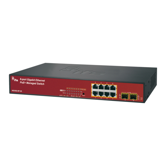
IFS NS3502-8P-2S User Manual 1. INTRODUTION The IFS 8-Port 10/100/1000Mbps PoE Plus + 2 100/1000X SFP Managed Ethernet Switch NS3502-8P-2S is multiple ports Gigabit Ethernet Switched with SFP fiber optical connective ability and robust layer 2 features; the description of these models as below:... - Page 20 IFS NS3502-8P-2S User Manual High-Performance, Cost-effective Gigabit solution for backbone of SMB The IFS NS3502-8P-2S is the Layer 2 Managed Gigabit Switch which can handle extremely large amounts of data in a secure topology linking to an Enterprise backbone or high capacity network server with 20Gbps switching fabric.
- Page 21 IFS NS3502-8P-2S User Manual Powerful Security IFS NS3502-8P-2S offers comprehensive Layer 2 to Layer 4 Access Control List (ACL) for enforcing security to the edge. It can be used to restrict network access by denying packets based on source and destination IP address, TCP/UDP ports or defined typical network applications. Its protection mechanism also comprises of 802.1x port-based and MAC-based user and device authentication.
-
Page 22: How To Use This Manual
IFS NS3502-8P-2S User Manual 1.3 How to Use This Manual This User Manual is structured as follows: Section 2, INSTALLATION The section explains the functions of the Switch and how to physically install the Managed Switch. Section 3, SWITCH MANAGEMENT The section contains the information about the software function of the Managed Switch. -
Page 23: Product Features
IFS NS3502-8P-2S User Manual 1.4 Product Features Physical Port NS3502-8P-2S 8-Port 10/100/1000Base-T Gigabit Ethernet RJ-45 with IEEE 802.3af / 802.3at PoE Injector 2 100/1000Base-X SFP slots RS-232 DB9 console interface for Switch basic management and setup ... - Page 24 IFS NS3502-8P-2S User Manual TOS / DSCP / IP Precedence of IPv4/IPv6 packets IP TCP/UDP port number Typical network application ■ Strict priority and Weighted Round Robin (WRR) CoS policies ■ Supports QoS and In/Out bandwidth control on each port ■...
- Page 25 IFS NS3502-8P-2S User Manual ■ Firmware upload/download via HTTP / TFTP ■ DHCP Relay ■ DHCP Option82 ■ User Privilege levels control ■ NTP (Network Time Protocol) ■ Link Layer Discovery Protocol (LLDP) Protocol ■ Cable Diagnostic technology provides the mechanism to detect and report potential cabling issues ■...
-
Page 26: Product Specification
IFS NS3502-8P-2S User Manual 1.5 Product Specification Product NS3502-8P-2S Hardware Specification Copper Ports 8 10/ 100/1000Base-T RJ-45 Auto-MDI/MDI-X ports 2 1000Base-SX/LX/BX SFP interfaces (Port-9 and Port-10) SFP/mini-GBIC Slots Compatible with 100Base-FX SFP Console Port 1 x RS-232 DB9 serial port (115200, 8, N, 1) - Page 27 IFS NS3502-8P-2S User Manual Basic Management Console, Telnet, Web Browser, SNMPv1, v2c Interfaces Secure Management SSH, SSL, SNMP v3 Interface Port disable/enable. Auto-negotiation 10/100/1000Mbps full and half duplex mode selection. Port configuration Flow Control disable / enable. Bandwidth control on each port.
- Page 28 IFS NS3502-8P-2S User Manual RFC-1213 MIB-II IF-MIB RFC-1493 Bridge MIB RFC-1643 Ethernet MIB RFC-2863 Interface MIB RFC-2665 Ether-Like MIB SNMP MIBs RFC-2737 Entity MIB RFC-2618 RADIUS Client MIB RFC-2933 IGMP-STD-MIB RFC3411 SNMP-Frameworks-MIB IEEE 802.1X PAE LLDP MAU-MIB Standards Conformance Regulation Compliance FCC Part 15 Class A, CE IEEE 802.3 10Base-T...
-
Page 29: Installation
IFS NS3502-8P-2S User Manual 2. INSTALLATION This section describes the hardware features and installation of the Managed Switch on the desktop or rack mount. For easier management and control of the Managed Switch, familiarize yourself with its display indicators, and ports. Front panel illustrations in this chapter display the unit LED indicators. -
Page 30: Led Indications
IFS NS3502-8P-2S User Manual Reset Button Pressed and Function Released < 5 sec: System reboot Reboot the Managed Switch Reset the Managed Switch to Factory Default configuration. The Managed Switch will then reboot and load the default settings as below: Default Username: admin 。... -
Page 31: Switch Rear Panel
IFS NS3502-8P-2S User Manual Per 10/100/1000Mbps port Color Function Lights to indicate the port is providing 52VDC in-line power Orange Off: indicate the connected device is not a PoE Powered Device (PD) In-Use Lights to indicate the port is running in 1000Mbps speed and 1000 successfully established. - Page 32 IFS NS3502-8P-2S User Manual The device is a power-required device, it means, it will not work till it is powered. If your networks should active all the time, please consider using UPS (Uninterrupted Power Supply) for your device. It will prevent you from network data loss or network downtime.
-
Page 33: Install The Switch
IFS NS3502-8P-2S User Manual 2.2 Install the Switch This section describes how to install your Managed Switch and make connections to the Managed Switch. Please read the following topics and perform the procedures in the order being presented. To install your Managed Switch on a desktop or shelf, simply complete the following steps. -
Page 34: Rack Mounting
IFS NS3502-8P-2S User Manual Step5: Supply power to the Managed Switch. Connect one end of the power cable to the Managed Switch. Connect the power plug of the power cable to a standard wall outlet. When the Managed Switch receives power, the Power LED should remain solid Green. -
Page 35: Installing The Sfp Transceiver
IFS NS3502-8P-2S User Manual Figure 2-6: Mounting NS3502-8P-2S in a Rack Step6: Proceeds with the steps 4 and steps 5 of session 2.2.1 Desktop Installation to connect the network cabling and supply power to the Managed Switch. 2.2.3 Installing the SFP transceiver The sections describe how to insert an SFP transceiver into an SFP slot. - Page 36 IFS NS3502-8P-2S User Manual Gigabit SFP Transceiver modules IFS Model SFP Description S30-1SLC/A-10 SFP, LC Connector, Single Mode, Gigabit, 1 fiber, 1310nm/1550nm, 10km , A S30-1SLC/A-20 SFP, LC Connector, Single Mode, Gigabit, 1 fiber, 1310nm/1550nm, 20km, A S30-1SLC/A-60 SFP, LC Connector, Single Mode, Gigabit, 1 fiber, 1310nm/1550nm, 60km, A...
- Page 37 IFS NS3502-8P-2S User Manual It recommends using IFS SFPs on the Managed Switch. If you insert a SFP transceiver that is not supported, the Managed Switch will not recognize Before connect the other Managed Switches, workstation or Media Converter. Make sure both side of the SFP transceiver are with the same media type, for example: 1000Base-SX to 1000Base-SX, 1000Bas-LX to 1000Base-LX.
- Page 38 IFS NS3502-8P-2S User Manual Figure 2-8: Pull out the SFP transceiver Never pull out the module without pull the handle or the push bolts on the module. Direct pull out the module with violent could damage the module and SFP module slot of the Managed Switch.
-
Page 39: Switch Management
IFS NS3502-8P-2S User Manual 3. SWITCH MANAGEMENT This chapter explains the methods that you can use to configure management access to the Managed Switch. It describes the types of management applications and the communication and management protocols that deliver data between your management device (workstation or personal computer) and the system. -
Page 40: Management Access Overview
IFS NS3502-8P-2S User Manual 3.2 Management Access Overview The Managed Switch gives you the flexibility to access and manage it using any or all of the following methods: An administration console Web browser interface An external SNMP-based network management application ... -
Page 41: Administration Console
IFS NS3502-8P-2S User Manual 3.3 Administration Console The administration console is an internal, character-oriented, and command line user interface for performing system administration such as displaying statistics or changing option settings. Using this method, you can view the administration console from a terminal, personal computer, Apple Macintosh, or workstation connected to the switch's console (serial) port. -
Page 42: Web Management
IFS NS3502-8P-2S User Manual Figure 3-2: Terminal parameter settings You can change these settings, if desired, after you log on. This management method is often preferred because you can remain connected and monitor the system during system reboots. Also, certain error messages are sent to the serial port, regardless of the interface through which the associated action was initiated. - Page 43 IFS NS3502-8P-2S User Manual You can then use your Web browser to list and manage the Managed Switch configuration parameters from one central location, just as if you were directly connected to the Managed Switch's console port. Web Management requires either Microsoft Internet Explorer 7.0 or later, Safari or Mozilla Firefox 1.5 or later.
- Page 44 IFS NS3502-8P-2S User Manual Figure 3-5: SNMP management...
-
Page 45: Web Configuration
IFS NS3502-8P-2S User Manual 4. WEB CONFIGURATION This section introduces the configuration and functions of the Web-Based management. About Web-based Management The Managed Switch offers management features that allow users to manage the Managed Switch from anywhere on the network through a standard browser such as Microsoft Internet Explorer. - Page 46 IFS NS3502-8P-2S User Manual Logging on the switch Use Internet Explorer 7.0 or above Web browser. Enter the factory-default IP address to access the Web interface. The factory-default IP Address as following: http://192.168.0.100 When the following login screen appears, please enter the default username "admin" with password “admin”...
- Page 47 IFS NS3502-8P-2S User Manual Default main page Figure 4-1-3: Now, you can use the Web management interface to continue the switch management or manage the Managed Switch by Web interface. The Switch Menu on the left of the web page let you access all the commands and statistics the Managed Switch provides.
-
Page 48: Main Web Page
IFS NS3502-8P-2S User Manual 4.1 Main Web Page The IFS Managed Switch provides a Web-based browser interface for configuring and managing it. This interface allows you to access the Managed Switch using the Web browser of your choice. This chapter describes how to use the Managed Switch’s Web browser interface to configure and manage it. - Page 49 IFS NS3502-8P-2S User Manual can setup the Managed Switch by select the functions those listed in the Main Function. The screen in Figure 4-1-5 appears. Managed Switch Main Functions Menu Figure 4-1-5:...
-
Page 50: System
IFS NS3502-8P-2S User Manual 4.2 System Use the System menu items to display and configure basic administrative details of the Managed Switch. Under System the following topics are provided to configure and view the system information: This section has the following items: ■... -
Page 51: System Information Page Screenshot
IFS NS3502-8P-2S User Manual 4.2.1 System Information The System Info page provides information for the current device information. System Info page helps a switch administrator to identify the hardware MAC address, software version and system uptime. The screen in Figure 4-2-1 appears. -
Page 52: Ip Configuration
IFS NS3502-8P-2S User Manual Buttons Auto-refresh : Check this box to enable an automatic refresh of the page at regular intervals. : Click to refresh the page; any changes made locally will be undone. 4.2.2 IP Configuration The IP Configuration includes the IP Address, Subnet Mask and Gateway. The Configured column is used to view or change the IP configuration. -
Page 53: Ipv6 Configuration
IFS NS3502-8P-2S User Manual • DNS Server Provide the IP address of the DNS Server in dotted decimal notation. • DNS Proxy When DNS proxy is enabled, DUT will relay DNS requests to the current configured DNS server on DUT, and reply as a DNS resolver to the client device on the network. -
Page 54: Users Configuration
IFS NS3502-8P-2S User Manual • Address Provide the IPv6 address of this switch. IPv6 address is in 128-bit records represented as eight fields of up to four hexadecimal digits with a colon separate each field (:). For example, ‘fae0::013:4fefe:dea4:34d4’ . The symbol '::' is a special syntax that can be used as a shorthand way of representing multiple 16-bit groups of contiguous zeros;... - Page 55 IFS NS3502-8P-2S User Manual Figure 4-2-4: Users Configuration page screenshot The page includes the following fields: Object Description • Username The name identifying the user. This is also a link to Add/Edit User. • Privilege Level The privilege level for the user.
- Page 56 IFS NS3502-8P-2S User Manual : Click to undo any changes made locally and revert to previously saved values. : Click to undo any changes made locally and return to the Users. : Delete the current user. This button is not available for new configurations (Add new user) Once the new user is added, the new user entry is shown in the Users Configuration page.
-
Page 57: Privilege Levels
IFS NS3502-8P-2S User Manual 4.2.5 Privilege Levels This page provides an overview of the privilege levels. After setup completed, please press “Save” button to take effect. Please login web interface with new user name and password, the screen in Figure 4-2-7 appears. - Page 58 IFS NS3502-8P-2S User Manual The page includes the following fields: Object Description • Group Name The name identifying the privilege group. In most cases, a privilege level group consists of a single module (e.g. LACP, RSTP or QoS), but a few of them contains more than one. The following description defines these privilege level groups in details: System: Contact, Name, Location, Timezone, Log.
-
Page 59: Ntp Configuration
IFS NS3502-8P-2S User Manual 4.2.6 NTP Configuration Configure NTP on this page. NTP is an acronym for Network Time Protocol, a network protocol for synchronizing the clocks of computer systems. NTP uses UDP (data grams) as transport layer. You can specify NTP Servers and set GMT Time zone. -
Page 60: Upnp
IFS NS3502-8P-2S User Manual Buttons : Click to save changes. : Click to undo any changes made locally and revert to previously saved values. 4.2.7 UPnP Configure UPnP on this page. UPnP is an acronym for Universal Plug and Play. The goals of UPnP are to allow devices to connect... - Page 61 IFS NS3502-8P-2S User Manual The page includes the following fields: Object Description • Mode Indicates the UPnP operation mode. Possible modes are: Enabled: Enable UPnP mode operation. Disabled: Disable UPnP mode operation. When the mode is enabled, two ACEs are added automatically to trap UPNP related packets to CPU.
-
Page 62: Dhcp Relay
IFS NS3502-8P-2S User Manual Buttons : Click to save changes. : Click to undo any changes made locally and revert to previously saved values. Figure 4-2-10: UPnP devices shows on Windows My Network Places 4.2.8 DHCP Relay Configure DHCP Relay on this page. DHCP Relay is used to forward and to transfer DHCP messages between the clients and the server when they are not on the same subnet domain. - Page 63 IFS NS3502-8P-2S User Manual The Circuit ID sub-option is supposed to include information specific to which circuit the request came in on. The Remote ID sub-option was designed to carry information relating to the remote host end of the circuit.
-
Page 64: Dhcp Relay Statistics
IFS NS3502-8P-2S User Manual specific information (option82) into a DHCP message when forwarding to DHCP server and remove it from a DHCP message when transferring to DHCP client. It only works under DHCP relay operation mode enabled. Disabled: Disable DHCP relay information mode operation. - Page 65 IFS NS3502-8P-2S User Manual • Transmit to Server The packets number that relayed from client to server. • Transmit Error The packets number has errors sending packets to clients. • Receive form The packets number that received packets from server.
-
Page 66: Cpu Load
IFS NS3502-8P-2S User Manual 4.2.10 CPU Load This page displays the CPU load, using a SVG graph. The load is measured as averaged over the last 100ms, 1sec and 10 seconds intervals. The last 120 samples are graphed, and the last numbers are displayed as text as well. -
Page 67: System Log
IFS NS3502-8P-2S User Manual 4.2.11 System Log The switch system log information is provided here. The System Log screen in Figure 4-2-14 appears. Figure 4-2-14: System Log page screenshot The page includes the following fields: Object Description • ID The ID (>= 1) of the system log entry. -
Page 68: Detailed Log
IFS NS3502-8P-2S User Manual : Updates the system log entries, ending at the last entry currently displayed. : Updates the system log entries, starting from the last entry currently displayed. : Updates the system log entries, ending at the last available entry ID. -
Page 69: Remote Syslog
IFS NS3502-8P-2S User Manual 4.2.13 Remote Syslog Configure remote syslog on this page. The Remote Syslog screen in Figure 4-2-16 appears. Figure 4-2-16: Remote Syslog page screenshot The page includes the following fields: Object Description • Mode Indicates the server mode operation. When the mode operation is enabled, the syslog message will send out to syslog server. -
Page 70: Smtp Configuration
IFS NS3502-8P-2S User Manual 4.2.14 SMTP Configuration Configure SMTP Configuration on this page. The SMTP Configuration screen in Figure 4-2-17 appears. Figure 4-2-17: SMTP Configuration Page Screenshot The page includes the following fields: Object Description • SMTP Mode Enabled It is for you to enable SMTP mode function. This mode offers you... -
Page 71: Led Power Reduction
IFS NS3502-8P-2S User Manual • E-mail From It is for you to input who send this mail. • E-mail Subject It is for you to input mail subject. • E-mail 1 To It is for you to input recipient mail address. -
Page 72: Eee Power Reduction
IFS NS3502-8P-2S User Manual The page includes the following fields: Object Description • Time The time at which the LEDs intensity shall be set. • Intensity The LEDs intensity (100% = Full power, 0% = LED off). • Maintenance Time When a network administrator does maintenance of the switch (e.g. -
Page 73: Thermal Protection
IFS NS3502-8P-2S User Manual The EEE Power Reduction screen in Figure 4-2-19 appears. Figure 4-2-19: EEE Configuration page screenshot The page includes the following fields: Object Description • Port The switch port number of the logical EEE port. • EEE Enable Controls whether EEE is enabled for this switch port. - Page 74 IFS NS3502-8P-2S User Manual Figure 4-2-20: Thermal Protection Configuration page screenshot The page includes the following fields: Object Description • Temperature The temperature at which the ports with the corresponding settings for priority priority will be turned off. Temperatures between 0 and 255 C groups are supported.
-
Page 75: Web Firmware Upgrade
IFS NS3502-8P-2S User Manual 4.2.18 Web Firmware Upgrade This page facilitates an update of the firmware controlling the switch. The Web Firmware Upgrade screen in Figure 4-2-21 appears. Figure 4-2-21: Web Firmware Upgrade page screenshot To open Firmware Upgrade screen perform the folling: 1. -
Page 76: Tftp Firmware Upgrade
IFS NS3502-8P-2S User Manual 4.2.19 TFTP Firmware Upgrade The Firmware Upgrade page provides the functions to allow a user to update the Managed Switch firmware from the TFTP server in the network. Before updating, make sure you have your TFTP server ready and the firmware image is on the TFTP server. -
Page 77: Save Configuration
IFS NS3502-8P-2S User Manual Figure 4-2-24: Configuration Save page screenshot You can save/view or load the switch configuration. The configuration file is in XML format with a hierarchy of tags: Header tags: <?xml version="1.0"?> and <configuration>. These tags are mandatory and must be present at the beginning of the file. - Page 78 IFS NS3502-8P-2S User Manual Figure 4-2-25: File Download screen 2. Chose the file save path in management workstation. Figure 4-2-26: File save screen...
-
Page 79: Configuration Upload
IFS NS3502-8P-2S User Manual 4.2.21 Configuration Upload This function allows backup and reload the current configuration of the Managed Switch to the local management station. The Configuration Upload screen in Figure 4-2-27 appears. Figure 4-2-27: Configuration Upload page screenshot Configuration Upload 1. -
Page 80: Factory Default
IFS NS3502-8P-2S User Manual 4.2.22 Factory Default You can reset the configuration of the stack switch on this page. Only the IP configuration is retained. The new configuration is available immediately, which means that no restart is necessary. The Factory... -
Page 81: System Reboot
IFS NS3502-8P-2S User Manual 4.2.23 System Reboot The Reboot page enables the device to be rebooted from a remote location. Once the Reboot button is pressed, user have to re-login the WEB interface about 60 seconds later, the System Reboot screen in Figure 4-2-30 appears. -
Page 82: Simple Network Management Protocol
IFS NS3502-8P-2S User Manual 4.3 Simple Network Management Protocol 4.3.1 SNMP Overview The Simple Network Management Protocol (SNMP) is an application layer protocol that facilitates the exchange of management information between network devices. It is part of the Transmission Control Protocol/Internet Protocol (TCP/IP) protocol suite. -
Page 83: Snmp System Configuration
IFS NS3502-8P-2S User Manual Use the SNMP Menu to display or configure the Managed Switch's SNMP function. This section has the following items: System Configuration Configure SNMP on this page. System Information The system information is provides here. ... - Page 84 IFS NS3502-8P-2S User Manual allowed content is the ASCII characters from 33 to 126. The field only suits to SNMPv1 and SNMPv2c. SNMPv3 is using USM for authentication and privacy and the community string will associated with SNMPv3 communities table.
- Page 85 IFS NS3502-8P-2S User Manual SNMP v2c: Set SNMP trap supported version 2c. SNMP v3: Set SNMP trap supported version 3. • Trap Community Indicates the community access string when send SNMP trap packet. The allowed string length is 0 to 255, and the allowed content is the ASCII characters from 33 to 126.
-
Page 86: Snmp System Information
IFS NS3502-8P-2S User Manual 4.3.3 SNMP System Information The switch system information is provided here. The SNMP System Information screen in Figure 4-3-3 appears. Figure 4-3-3: System Information Configuration page screenshot The page includes the following fields: Object Description •... -
Page 87: Snmpv3 Configuration
IFS NS3502-8P-2S User Manual 4.3.4 SNMPv3 Configuration 4.3.4.1 SNMPv3 Communities Configure SNMPv3 communities table on this page. The entry index key is Community. The SNMPv3 Communities screen in Figure 4-3-4 appears. Figure 4-3-4: SNMPv3 Communities Configuration page screenshot The page includes the following fields:... -
Page 88: Snmpv3 Users
IFS NS3502-8P-2S User Manual 4.3.4.2 SNMPv3 Users Configure SNMPv3 users table on this page. The entry index keys are Engine ID and User Name. The SNMPv3 Users screen in Figure 4-3-5 appears. Figure 4-3-5: SNMPv3 Users Configuration page screenshot The page includes the following fields:... - Page 89 IFS NS3502-8P-2S User Manual • Authentication A string identifying the authentication pass phrase. For MD5 Password authentication protocol, the allowed string length is 8 to 32. For SHA authentication protocol, the allowed string length is 8 to 40. The allowed content is the ASCII characters from 33 to 126.
-
Page 90: Snmpv3 Groups
IFS NS3502-8P-2S User Manual 4.3.4.3 SNMPv3 Groups Configure SNMPv3 groups table on this page. The entry index keys are Security Model and Security Name. The SNMPv3 Groups screen in Figure 4-3-6 appears. Figure 4-3-6: SNMPv3 Groups Configuration page screenshot The page includes the following fields:... -
Page 91: Snmpv3 Views
IFS NS3502-8P-2S User Manual 4.3.4.4 SNMPv3 Views Configure SNMPv3 views table on this page. The entry index keys are View Name and OID Subtree. The SNMPv3 Views screen in Figure 4-3-7 appears. Figure 4-3-7: SNMPv3 Views Configuration page screenshot The page includes the following fields:... -
Page 92: Snmpv3 Access
IFS NS3502-8P-2S User Manual 4.3.4.5 SNMPv3 Access Configure SNMPv3 accesses table on this page. The entry index keys are Group Name, Security Model and Security Level. The SNMPv3 Access screen in Figure 4-3-8 appears. Figure 4-3-8: SNMPv3 Accesses Configuration page screenshot... - Page 93 IFS NS3502-8P-2S User Manual Buttons : Click to add a new access entry. : Click to save changes. : Click to undo any changes made locally and revert to previously saved values.
-
Page 94: Port Management
IFS NS3502-8P-2S User Manual 4.4 Port Management Use the Port Menu to display or configure the Managed Switch's ports. This section has the following items: Port Configuration Configures port connection settings Port Statistics Lists Ethernet and RMON port statistics... - Page 95 IFS NS3502-8P-2S User Manual • Configured Link Select any available link speed for the given switch port. Draw the Speed menu bar to select the mode. Auto Speed - Setup Auto negotiation. 10 Half - Force sets 10Mbps/Half-Duplex mode. 10 Full - Force sets 10Mbps/Full-Duplex mode.
-
Page 96: Port Statistics Overview
IFS NS3502-8P-2S User Manual : Click to refresh the page. Any changes made locally will be undone. 4.4.2 Port Statistics Overview This page provides an overview of general traffic statistics for all switch ports. The Port Statistics Overview screen in Figure 4-4-2 appears. -
Page 97: Port Thermal Protection Status
IFS NS3502-8P-2S User Manual 4.4.3 Port Thermal Protection Status This page allows the user to inspect status information related to thermal protection. The Port Thermal Protection Status screen in Figure 4-4-3 appears. Figure 4-4-3: Thermal Protection Status page screenshot The displayed counters are:... - Page 98 IFS NS3502-8P-2S User Manual Figure 4-4-4: Detailed Port Statistics Port 1 page screenshot The page includes the following fields: Receive Total and Transmit Total Object Description • Rx and Tx Packets The number of received and transmitted (good and bad) packets •...
- Page 99 IFS NS3502-8P-2S User Manual Receive and Transmit Queue Counters The number of received and transmitted packets per input and output queue. Receive Error Counters Object Description • The number of frames dropped due to lack of receive buffers or Rx Drops egress congestion.
-
Page 100: Sfp Information
IFS NS3502-8P-2S User Manual 4.4.5 SFP Information You can check the physical or operational status of an SFP module via the SFP Module Information page. This page shows the operational status, such as the transceiver type, speed, and wavelength and supports distance of SFP module on a specific interface. -
Page 101: Port Mirror
IFS NS3502-8P-2S User Manual 4.4.6 Port Mirror Configure port Mirroring on this page. This function provide to monitoring network traffic that forwards a copy of each incoming or outgoing packet from one port of a network Switch to another port where the packet can be studied. It enables the manager to keep close track of switch performance and alter it if necessary. - Page 102 IFS NS3502-8P-2S User Manual Mirror Port Configuration The Port Mirror screen in Figure 4-4-7 appears. Figure 4-4-7: Mirror Configuration page screenshot The page includes the following fields: Object Description • Port to mirror on Frames from ports that have either source (rx) or destination (tx) mirroring enabled are mirrored to this port.
- Page 103 IFS NS3502-8P-2S User Manual Buttons : Click to save changes. : Click to undo any changes made locally and revert to previously saved values.
-
Page 104: Link Aggregation
IFS NS3502-8P-2S User Manual 4.5 Link Aggregation Port Aggregation optimizes port usage by linking a group of ports together to form a single Link Aggregated Groups (LAGs). Port Aggregation multiplies the bandwidth between the devices, increases port flexibility, and provides link redundancy. - Page 105 IFS NS3502-8P-2S User Manual The Link Aggregation Control Protocol (LACP) provides a standardized means for exchanging information between Partner Systems that require high speed redundant links. Link aggregation lets you group up to eight consecutive ports into a single dedicated connection. This feature can expand bandwidth to a device on the network.
- Page 106 IFS NS3502-8P-2S User Manual member ports. Any quantity of link aggregation s may be configured for the device (only limited by the quantity of ports on the device.) To configure a proper traffic distribution, the ports within a link aggregation must use the same link speed.
-
Page 107: Static Aggregation
IFS NS3502-8P-2S User Manual 4.5.1 Static Aggregation This page is used to configure the Aggregation hash mode and the aggregation group. The aggregation hash mode settings are global, whereas the aggregation group relate to the currently selected stack unit, as reflected by the page header. - Page 108 IFS NS3502-8P-2S User Manual Figure 4-5-3: Aggregation Group Configuration page screenshot The page includes the following fields: .Object Description • Indicates the group ID for the settings contained in the same row. Group ID Group ID "Normal" indicates there is no aggregation. Only one group ID is valid per port.
-
Page 109: Lacp Configuration
IFS NS3502-8P-2S User Manual 4.5.2 LACP Configuration Link Aggregation Control Protocol (LACP) - LACP LAG negotiate Aggregated Port links with other LACP ports located on a different device. LACP allows switches connected to each other to discover automatically whether any ports are member of the same LAG. -
Page 110: Lacp System Status
IFS NS3502-8P-2S User Manual can participate in the same aggregation group, while ports with different keys cannot. The default setting is “Auto” • The Role shows the LACP activity status. The Active will transmit Role LACP packets each second; while Passive will wait for a LACP packet from a partner (speak if spoken to). -
Page 111: Lacp Port Status
IFS NS3502-8P-2S User Manual : Click to refresh the page immediately. Auto-refresh : Check this box to enable an automatic refresh of the page at regular intervals. 4.5.4 LACP Port Status This page provides a status overview for LACP status for all ports. The LACP Port Status screen in... -
Page 112: Lacp Port Statistics
IFS NS3502-8P-2S User Manual Buttons : Click to refresh the page immediately. Auto-refresh : Check this box to enable an automatic refresh of the page at regular intervals. 4.5.5 LACP Port Statistics This page provides an overview for LACP statistics for all ports. The LACP Port Statistics screen in... -
Page 113: Vlan
IFS NS3502-8P-2S User Manual 4.6 VLAN 4.6.1 VLAN Overview A Virtual Local Area Network (VLAN) is a network topology configured according to a logical scheme rather than the physical layout. VLAN can be used to combine any collection of LAN segments into an autonomous user group that appears as a single LAN. -
Page 114: Ieee 802.1Q Vlan
IFS NS3502-8P-2S User Manual MAC-based VLAN Displays MAC-based VLAN entries Status Protocol-based VLAN Configures the protocol-based VLAN entries Protocol-based VLAN Displays the protocol-based VLAN entries Membership 4.6.2 IEEE 802.1Q VLAN In large networks, routers are used to isolate broadcast traffic for each subnet into separate domains. - Page 115 IFS NS3502-8P-2S User Manual VLAN can also provide a level of security to your network. IEEE 802.1Q VLAN will only deliver packets between stations that are members of the VLAN. Any port can be configured as either tagging or untagging.
- Page 116 IFS NS3502-8P-2S User Manual Adding an IEEE802.1Q Tag Dest. Addr. Src. Addr. Length/E. type Data Old CRC Original Ethernet Packet Dest. Addr. Src. Addr. E. type Length/E. type Data New CRC New Tagged Packet Priority VLAN ID ■ Port VLAN ID Packets that are tagged (are carrying the 802.1Q VID information) can be transmitted from one 802.1Q...
-
Page 117: Vlan Basic Information
IFS NS3502-8P-2S User Manual Before enabling VLANs for the switch, you must first assign each port to the VLAN group(s) in which it will participate. By default all ports are assigned to VLAN 1 as untagged ports. Add a port as a tagged port if you want it to carry traffic for one or more VLANs, and any intermediate network devices or the host at the other end of the connection supports VLANs. -
Page 118: Vlan Port Configuration
IFS NS3502-8P-2S User Manual Figure 4-6-1: VLAN Basic Information page screenshot The page includes the following fields: Object Description • Mode Display the current VLAN mode used by this Managed Switch Port-Based IEEE 802.1Q VLAN • Maximum VLAN ID Maximum VLAN ID recognized by this Managed Switch. - Page 119 IFS NS3502-8P-2S User Manual Every port on an 802.1Q compliant switch can be configured as tagged or untagged. • Tagged: Ports with tagging enabled will put the VID number, priority and other VLAN information into the header of all packets that flow into those ports. If a packet has previously been tagged, the port will not alter the packet, thus keeping the VLAN information intact.
- Page 120 IFS NS3502-8P-2S User Manual The Managed Switch supports multiple VLAN tags and can therefore be used in MAN applications as a provider bridge, aggregating traffic from numerous independent customer LANs into the MAN (Metro Access Network) space. One of the purposes of the provider bridge is to recognize and use VLAN tags so that the VLANs in the MAN space can be used independent of the customers’...
- Page 121 IFS NS3502-8P-2S User Manual VLAN Port Configuration The VLAN Port Configuration screen in Figure 4-6-2 appears. Figure 4-6-2: VLAN Port Configuration page screenshot The page includes the following fields: Object Description • Port This is the logical port number for this row.
- Page 122 IFS NS3502-8P-2S User Manual - Untag: outgoing frames without VLAN-Tagged. - Tagged: outgoing frames with VLAN-Tagged. • Q-in-Q Mode Sets the Managed Switch to QinQ mode, and allows the QinQ tunnel port to be configured. The default is for the Managed Switch to function in Disable mode.
-
Page 123: Vlan Membership
IFS NS3502-8P-2S User Manual 4.6.5 VLAN Membership Adding Static Members to VLANs (VLAN Index) Use the VLAN Static Table to configure port members for the selected VLAN index. The VLAN membership configuration for the selected stack switch / unit switch can be monitored and modified here. -
Page 124: Vlan Membership Status
IFS NS3502-8P-2S User Manual switch units, but with no port members. A VLAN without any port members on any stack unit will be deleted when you click "Save". The button can be used to undo the addition of new VLANs. - Page 125 IFS NS3502-8P-2S User Manual (selection shall be allowed by a Combo Box). When ALL VLAN Users is selected, it shall show this information for all the VLAN Users, and this is the default. VLAN membership allows the frames Classified to the VLAN ID to be forwarded to the respective VLAN member ports.
-
Page 126: Vlan Port Status
IFS NS3502-8P-2S User Manual 4.6.7 VLAN Port Status This page provides VLAN Port Status. The VLAN Port Status screen in Figure 4-6-5 appears. Figure 4-6-5: VLAN Port Status for Static User page screenshot The page includes the following fields: Object Description •... -
Page 127: Private Vlan
IFS NS3502-8P-2S User Manual packet's behavior at the egress side. • Conflicts Shows status of Conflicts whether exists or Not. When a Volatile VLAN User requests to set VLAN membership or VLAN port configuration, the following conflicts can occur: Functional Conflicts between features. - Page 128 IFS NS3502-8P-2S User Manual Private VLANs are based on the source port mask, and there are no connections to VLANs. This means that VLAN IDs and Private VLAN IDs can be identical. A port must be a member of both a VLAN and a Private VLAN to be able to forward packets. By default, all ports are VLAN unaware and members of VLAN 1 and Private VLAN 1.
-
Page 129: Port Isolation
IFS NS3502-8P-2S User Manual 4.6.9 Port Isolation Overview When a VLAN is configured to be a private VLAN, communication between ports within that VLAN can be prevented. Two application examples are provided in this section: • Customers connected to an ISP can be members of the same VLAN, but they are not allowed to communicate with each other within that VLAN. -
Page 130: Vlan Setting Example
IFS NS3502-8P-2S User Manual VLAN table. This reduces the ports to which forwarding can be done to just the promiscuous ports within the private VLAN. This page is used for enabling or disabling port isolation on ports in a Private VLAN. A port member of a VLAN can be isolated to other isolated ports on the same VLAN and Private VLAN. - Page 131 IFS NS3502-8P-2S User Manual members of the VLAN receive traffic from the same VLAN members. The screen in Figure 4-6-8 appears Table 4-6-9 describes the port configuration of the Managed Switches. Figure 4-6-8: two separate VLAN diagram VLAN Group Untagged Members...
- Page 132 IFS NS3502-8P-2S User Manual Untagged packet entering VLAN 3 While [PC-4] transmit an untagged packet enters Port-4, the switch will tag it with a VLAN Tag=3. [PC-5] and [PC-6] will received the packet through Port-5 and Port-6. While the packet leaves Port-5, it will be stripped away on a tag becoming an untagged packet.
-
Page 133: Vlan Trunking Between Two 802.1Q Aware Switch
IFS NS3502-8P-2S User Manual Port-1, Port-2 and Port-3 : PVID=2 Port-4, Port-5 and Port-6 : PVID=3 Port-7~Port-24: PVID=1 5. Enable VLAN Tag for specific ports Link Type: Port-3 (VLAN-2) and Port-6 (VLAN-3) The Per Port VLAN configuration in Figure 4-6-10 appears. - Page 134 IFS NS3502-8P-2S User Manual Setup steps 1. Create VLAN Group Set VLAN Group 1 = Default-VLAN with VID (VLAN ID) =1 Add two VLANs – VLAN 2 and VLAN 3 VLAN Group 2 with VID=2 VLAN Group 3 with VID=3 2.
-
Page 135: Port Isolate
IFS NS3502-8P-2S User Manual 4. Assign the VLAN Trunk Port to be the member of each VLAN – which wants to be aggregated. At this sample, add Port-8 to be VLAN 2 and VLAN 3 member port. The screen in Figure 4-6-12 appears. - Page 136 IFS NS3502-8P-2S User Manual Setup steps 1. Assign Port Mode Set Port-1~Port-4 in Isolate port. Set Port5 and Port-6 in Promiscuous port. The screen in Figure 4-6-15 appears. Figure 4-6-15: The configuration of Isolate and Promiscuous port 2. Assign VLAN Member : VLAN 1 : Port-1, Port-2, Port-5 and Port-3 VLAN 2: Port-3~Port-6.
-
Page 137: Mac-Based Vlan
IFS NS3502-8P-2S User Manual Figure 4-6-16: Private VLAN port setting 4.6.11 MAC-based VLAN The MAC-based VLAN entries can be configured here. This page allows for adding and deleting MAC-based VLAN entries and assigning the entries to different ports. This page shows only static entries. -
Page 138: Mac-Based Vlan Status
IFS NS3502-8P-2S User Manual 4.6.12 MAC-based VLAN Status This page shows MAC-based VLAN entries configured by various MAC-based VLAN users. The MAC-based VLAN Status screen in Figure 4-6-18 appears. Figure 4-6-18: MAC-based VLAN Membership Configuration for User Static page screenshot... -
Page 139: Protocol-Based Vlan
IFS NS3502-8P-2S User Manual 4.6.13 Protocol-based VLAN This page allows you to add new protocols to Group Name (unique for each Group), mapping entries as well as allowing you to see and delete already mapped entries for the switch. The Protocol-based VLAN... -
Page 140: Protocol-Based Vlan Membership
IFS NS3502-8P-2S User Manual 3. For SNAP: Valid value in this case also is comprised of two different sub-values. a.OUI: OUI (Organizationally Unique Identifier) is value in format of xx-xx-xx where each pair (xx) in string is a hexadecimal value ranges from 0x00-0xff. - Page 141 IFS NS3502-8P-2S User Manual Figure 4-6-20: Group Name to VLAN Mapping Table page screenshot The page includes the following fields: Object Description • Delete To delete a Group Name to VLAN map entry, check this box. The entry will be deleted on the switch during the next Save •...
-
Page 142: Spanning Tree Protocol
IFS NS3502-8P-2S User Manual 4.7 Spanning Tree Protocol 4.7.1 Theory The Spanning Tree protocol can be used to detect and disable network loops, and to provide backup links between switches, bridges or routers. This allows the switch to interact with other bridging devices in your network to ensure that only one route exists between any two stations on the network, and provide backup links which automatically take over when a primary link goes down. - Page 143 IFS NS3502-8P-2S User Manual The path cost to the root from the transmitting port The port identifier of the transmitting port The switch sends BPDUs to communicate and construct the spanning-tree topology. All switches connected to the LAN on which the packet is transmitted will receive the BPDU. BPDUs are not directly forwarded by the switch, but the receiving switch uses the information in the frame to calculate a BPDU, and, if the topology changes, initiates a BPDU transmission.
- Page 144 IFS NS3502-8P-2S User Manual Disabled – the port only responds to network management messages and must return to the blocking state first A port transitions from one state to another as follows: From initialization (switch boot) to blocking ...
- Page 145 IFS NS3502-8P-2S User Manual 2. STP Parameters STP Operation Levels The Switch allows for two levels of operation: the switch level and the port level. The switch level forms a spanning tree consisting of links between one or more switches. The port level constructs a spanning tree consisting of groups of one or more ports.
- Page 146 IFS NS3502-8P-2S User Manual The following are the user-configurable STP parameters for the port or port group level: Variable Description Default Value Port A relative priority for each Priority port –lower numbers give a higher priority and a greater chance of a...
- Page 147 IFS NS3502-8P-2S User Manual Forward Delay Timer – The Forward Delay can be from 4 to 30 seconds. This is the time any port on the Switch spends in the listening state while moving from the blocking state to the forwarding state.
- Page 148 IFS NS3502-8P-2S User Manual Figure 4-7-5: Before Applying the STA Rules In this example, only the default STP values are used. Figure 4-7-6: After Applying the STA Rules...
-
Page 149: Stp System Configuration
IFS NS3502-8P-2S User Manual The switch with the lowest Bridge ID (switch C) was elected the root bridge, and the ports were selected to give a high port cost between switches B and C. The two (optional) Gigabit ports (default port cost = 20,000) on switch and are connected to one (optional) Gigabit port on both switch B and C. - Page 150 IFS NS3502-8P-2S User Manual The page includes the following fields: Basic Settings Object Description • The STP protocol version setting. Valid values are STP, RSTP and Protocol Version MSTP. • Bridge Priority Controls the bridge priority. Lower numeric values have better priority.
-
Page 151: Bridge Status
IFS NS3502-8P-2S User Manual error-disabled state, and will be removed from the active topology. • Port Error Recovery Control whether a port in the error-disabled state automatically will be enabled after a certain time. If recovery is not enabled, ports have to be disabled and re-enabled for normal STP operation. -
Page 152: Cist Port Configuration
IFS NS3502-8P-2S User Manual • The Bridge ID of this Bridge instance. Bridge ID • The Bridge ID of the currently elected root bridge. Root ID • The switch port currently assigned the root port role. Root Port • Root Cost Root Path Cost. - Page 153 IFS NS3502-8P-2S User Manual • STP Enabled Controls whether RSTP is enabled on this switch port. • Path Cost Controls the path cost incurred by the port. The Auto setting will set the path cost as appropriate by the physical link speed, using the 802.1D recommended values.
- Page 154 IFS NS3502-8P-2S User Manual the administrator or the physical link state of the attached LANs transits frequently. • BPDU Guard If enabled, causes the port to disable itself upon receiving valid BPDU's. Contrary to the similar bridge setting, the port Edge status does not affect this setting.
- Page 155 IFS NS3502-8P-2S User Manual Port Type Link Type IEEE 802.1w-2001 Ethernet Half Duplex 2,000,000 Full Duplex 1,000,000 Trunk 500,000 Fast Ethernet Half Duplex 200,000 Full Duplex 100,000 Trunk 50,000 Gigabit Ethernet Full Duplex 10,000 Trunk 5,000 Table 4-7-3: Default STP Path Costs...
-
Page 156: Msti Priorities
IFS NS3502-8P-2S User Manual 4.7.5 MSTI Priorities This page allows the user to inspect the current STP MSTI bridge instance priority configurations, and possibly change them as well. The MSTI Priority screen in Figure 4-7-10 appears. Figure 4-7-10: MSTI Priority page screenshot... -
Page 157: Msti Configuration
IFS NS3502-8P-2S User Manual 4.7.6 MSTI Configuration This page allows the user to inspect the current STP MSTI bridge instance priority configurations, and possibly change them as well. The MSTI Configuration screen in Figure 4-7-11 appears. Figure 4-7-11: MSTI Configuration page screenshot... -
Page 158: Msti Ports Configuration
IFS NS3502-8P-2S User Manual VLAN-to-MSTI mapping configuration in order to share spanning trees for MSTI's. (Intra-region). The name is at most 32 characters. • Configuration The revision of the MSTI configuration named above. This must Revision be an integer between 0 and 65535. - Page 159 IFS NS3502-8P-2S User Manual MSTI Port Configuration Object Description • Select MSTI Select the bridge instance and set more detail configuration. Figure 4-7-13: MST1 MSTI Port Configuration page screenshot The page includes the following fields: MSTx MSTI Port Configuration Object Description •...
-
Page 160: Port Status
IFS NS3502-8P-2S User Manual ports. Valid values are in the range 1 to 200000000. • Priority Controls the port priority. This can be used to control priority of ports having identical port cost. (See above). Buttons : Click to set MSTx configuration : Click to refresh the page immediately. -
Page 161: Port Statistics
IFS NS3502-8P-2S User Manual • State The current STP port state of the CIST port. The port state can be one of the following values: Disabled Blocking Learning Forwarding Non-STP • Uptime The time since the bridge port was last initialized. - Page 162 IFS NS3502-8P-2S User Manual • Discarded The number of unknown Spanning Tree BPDU's received (and Unknown discarded) on the port. • Discarded Illegal The number of illegal Spanning Tree BPDU's received (and discarded) on the port. Buttons : Click to refresh the page immediately.
-
Page 163: Multicast
IFS NS3502-8P-2S User Manual 4.8 Multicast 4.8.1 IGMP Snooping The Internet Group Management Protocol (IGMP) lets host and routers share information about multicast groups memberships. IGMP snooping is a switch feature that monitors the exchange of IGMP messages and copies them to the CPU for feature processing. The overall purpose of IGMP Snooping is to limit the forwarding of multicast frames to only ports that are a member of the multicast group. - Page 164 IFS NS3502-8P-2S User Manual Figure 4-8-1: Multicast Service Figure 4-8-2: Multicast flooding...
- Page 165 IFS NS3502-8P-2S User Manual Figure 4-8-3: IGMP Snooping multicast stream control IGMP Versions 1 and 2 Multicast groups allow members to join or leave at any time. IGMP provides the method for members and multicast routers to communicate when joining or leaving a multicast group.
- Page 166 IFS NS3502-8P-2S User Manual The Time-to-Live (TTL) field of query messages is set to 1 so that the queries will not be forwarded to other sub networks. IGMP version 2 introduces some enhancements such as a method to elect a multicast queried for each LAN, an explicit leave message, and query messages that are specific to a given group.
-
Page 167: Igmp Snooping Configuration
IFS NS3502-8P-2S User Manual 4.8.2 IGMP Snooping Configuration This page provides IGMP Snooping related configuration. The IGMP Snooping Configuration screen in Figure 4-8-5 appears. Figure 4-8-5: IGMP Snooping Configuration page screenshot The page includes the following fields: Object Description •... -
Page 168: Igmp Snooping Vlan Configuration
IFS NS3502-8P-2S User Manual whole aggregation will act as a router port. • Fast Leave Enable the fast leave on the port. • Throtting Enable to limit the number of multicast groups to which a switch port can belong. Buttons : Click to save changes. -
Page 169: Igmp Snooping Port Group Filtering
IFS NS3502-8P-2S User Manual 255; default robustness variable value is 2. • QI Query Interval. The Query Interval is the interval between General Queries sent by the Querier. The allowed range is 1 to 255 seconds; default query interval is 125 seconds. -
Page 170: Igmp Snooping Status
IFS NS3502-8P-2S User Manual join report is forwarded as normal. If a requested multicast group is denied, the IGMP join report is dropped. IGMP throttling sets a maximum number of multicast groups that a port can join at the same time. - Page 171 IFS NS3502-8P-2S User Manual Figure 4-8-8: IGMP Snooping Status page screenshot The page includes the following fields: Object Description • VLAN ID The VLAN ID of the entry. • Working Querier Version currently. Querier Version • Working Host Version currently.
-
Page 172: Igmp Group Information
IFS NS3502-8P-2S User Manual 4.8.6 IGMP Group Information Entries in the IGMP Group Table are shown on this page. The IGMP Group Table is sorted first by VLAN ID, and then by group. Each page shows up to 99 entries from the IGMP Group table, default being 20, selected through the "entries per page"... -
Page 173: Igmpv3 Information
IFS NS3502-8P-2S User Manual 4.8.7 IGMPv3 Information Entries in the IGMP SSM Information Table are shown on this page. The IGMP SSM Information Table is sorted first by VLAN ID, then by group, and then by Port No. Different source addresses belong to the same group are treated as single entry. -
Page 174: Mld Snooping Configuration
IFS NS3502-8P-2S User Manual 4.8.8 MLD Snooping Configuration This page provides MLD Snooping related configuration. The MLD Snooping Configuration screen in Figure 4-8-11 appears. Figure 4-8-11: MLD Snooping Configuration page screenshot The page includes the following fields: Object Description •... -
Page 175: Mld Snooping Vlan Configuration
IFS NS3502-8P-2S User Manual • Router Port Specify which ports act as router ports. A router port is a port on the Ethernet switch that leads towards the Layer 3 multicast device or MLD querier. If an aggregation member port is selected as a router port, the whole aggregation will act as a router port. - Page 176 IFS NS3502-8P-2S User Manual • MLD Querier Enable the MLD Querier in the VLAN. • RV Robustness Variable. The Robustness Variable allows tuning for the expected packet loss on a link. The allowed range is 1 to 255, default robustness variable value is 2.
-
Page 177: Mld Snooping Port Group Filtering
IFS NS3502-8P-2S User Manual 4.8.10 MLD Snooping Port Group Filtering In certain switch applications, the administrator may want to control the multicast services that are available to end users. For example, an IP/TV service based on a specific subscription plan. The MLD filtering feature fulfills this requirement by restricting access to specified multicast services on a switch port, and MLD throttling limits the number of simultaneous multicast groups a port can join. -
Page 178: Mld Snooping Status
IFS NS3502-8P-2S User Manual 4.8.11 MLD Snooping Status This page provides MLD Snooping status. The IGMP Snooping Status screen in Figure 4-8-14 appears. Figure 4-8-14: MLD Snooping Status page screenshot The page includes the following fields: Object Description • The VLAN ID of the entry. -
Page 179: Mld Group Information
IFS NS3502-8P-2S User Manual : Clears all Statistics counters. Auto-refresh : Check this box to enable an automatic refresh of the page at regular intervals. 4.8.12 MLD Group Information Entries in the MLD Group Table are shown on this page. The MLD Group Table is sorted first by VLAN ID, and then by group. -
Page 180: Mldv2 Information
IFS NS3502-8P-2S User Manual 4.8.13 MLDv2 Information Entries in the MLD SSM Information Table are shown on this page. The MLD SSM Information Table is sorted first by VLAN ID, then by group, and then by Port No. Different source addresses belong to the same group are treated as single entry. -
Page 181: Mvr
IFS NS3502-8P-2S User Manual 4.8.14 MVR In multicast VLAN networks, subscribers to a multicast group can exist in more than one VLAN. If the VLAN boundary restrictions in a network consist of Layer 2 switches Multicast VLAN Registration (MVR) is a protocol for Layer 2 (IP)-networks that enables multicast-traffic from a source VLAN to be shared with subscriber-VLANs. -
Page 182: Mvr Status
IFS NS3502-8P-2S User Manual • Immediate Leave Enable the fast leave on the port. Buttons : Click to save changes. : Click to undo any changes made locally and revert to previously saved values. 4.8.15 MVR Status This page provides MVR status. The MVR Status screen in Figure 4-8-18 appears. -
Page 183: Mvr Groups Information
IFS NS3502-8P-2S User Manual 4.8.16 MVR Groups Information Entries in the MVR Group Table are shown on this page. The MVR Group Table is sorted first by VLAN ID, and then by group. Each page shows up to 99 entries from the MVR Group table, default being 20, selected through the "entries per page"... -
Page 184: Quality Of Service
IFS NS3502-8P-2S User Manual 4.9 Quality of Service 4.9.1 Understand QOS Quality of Service (QoS) is an advanced traffic prioritization feature that allows you to establish control over network traffic. QoS enables you to assign various grades of network service to different types of traffic, such as multi-media, video, protocol-specific, time critical, and file-backup traffic. -
Page 185: Port Policing
IFS NS3502-8P-2S User Manual To implement QoS on your network, you need to carry out the following actions: Define a service level to determine the priority that will be applied to traffic. Apply a classifier to determine how the incoming traffic will be classified and thus treated by the Switch. -
Page 186: Port Classification
IFS NS3502-8P-2S User Manual : Click to save changes. : Click to undo any changes made locally and revert to previously saved values. 4.9.3 Port Classification This page allows you to configure the basic QoS Ingress Classification settings for all switch ports. The... -
Page 187: Qos Ingress Port Tag Classification
IFS NS3502-8P-2S User Manual Click on the mode in order to configure the mode and/or mapping. For more detail information, please refer to chapter 4.9.3.1. • Click to Enable DSCP Based QoS Ingress Port Classification. DSCP Based Buttons : Click to save changes. - Page 188 IFS NS3502-8P-2S User Manual Figure 4-9-3: QoS Ingress Port Tag Classification page screenshot The page includes the following fields: Object Description • Controls the classification mode for tagged frames on this port. Tag Classification Disabled: Use default QoS class and DP level for tagged frames.
-
Page 189: Port Scheduler
IFS NS3502-8P-2S User Manual : Click to undo any changes made locally and revert to previously saved values. : Return to the previous page. 4.9.4 Port Scheduler This page provides an overview of QoS Egress Port Schedulers for all switch ports. The Port Scheduler... -
Page 190: Qos Egress Port Schedule And Shapers
IFS NS3502-8P-2S User Manual Figure 4-9-5: QoS Egress Port Shapers page screenshot The page includes the following fields: Object Description • Port The logical port for the settings contained in the same row. Click on the port number in order to configure the shapers. - Page 191 IFS NS3502-8P-2S User Manual Figure 4-9-6: QoS Egress Port Schedule and Shapers page screenshot The page includes the following fields: Object Description • Schedule Mode Controls whether the scheduler mode is "Strict Priority" or "Weighted" on this switch port. • Queue Shaper...
-
Page 192: Port Tag Remarking
IFS NS3502-8P-2S User Manual This value is restricted to 100-1000000 when the "Unit" is "kbps", and it is restricted to 1-3300 when the "Unit" is "Mbps". • Port Shaper Unit Controls the unit of measure for the port shaper rate as "kbps" or "Mbps". -
Page 193: Qos Egress Port Tag Remarking
IFS NS3502-8P-2S User Manual 4.9.6.1 QoS Egress Port Tag Remarking The QoS Egress Port Tag Remarking for a specific port is configured on this page. The QoS Egress Port Tag Remarking screen in Figure 4-9-8 appears. Figure 4-9-8: QoS Egress Port Tag Remarking page screenshot... - Page 194 IFS NS3502-8P-2S User Manual Figure 4-9-9: QoS Port DSCP Configuration page screenshot The page includes the following fields: Object Description • Port The Port column shows the list of ports for which you can configure dscp ingress and egress settings.
-
Page 195: Dscp-Based Qos
IFS NS3502-8P-2S User Manual remarked with remapped DSCP value. Buttons : Click to save changes. : Click to undo any changes made locally and revert to previously saved values. Auto-refresh : Check this box to enable an automatic refresh of the page at regular intervals. - Page 196 IFS NS3502-8P-2S User Manual Figure 4-9-10: DSCP-Based QoS Ingress Classification page screenshot The page includes the following fields:...
-
Page 197: Dscp Translation
IFS NS3502-8P-2S User Manual Object Description • DSCP Maximum number of supported DSCP values is 64. • Trust Click to check if the DSCP value is trusted. • QoS Class QoS Class value can be any of (0-7) • Drop Precedence Level (0-1) Buttons : Click to save changes. - Page 198 IFS NS3502-8P-2S User Manual...
- Page 199 IFS NS3502-8P-2S User Manual Figure 4-9-11: DSCP Translation page screenshot The page includes the following fields: Object Description • DSCP Maximum number of supported DSCP values is 64 and valid DSCP value ranges from 0 to 63. • Ingress Ingress side DSCP can be first translated to new DSCP before using the DSCP for QoS class and DPL map.
-
Page 200: Dscp Classification
IFS NS3502-8P-2S User Manual 4.9.10 DSCP Classification This page allows you to map DSCP value to a QoS Class and DPL value. The DSCP Classification screen in Figure 4-9-12 appears. Figure 4-9-12: DSCP Classification page screenshot The page includes the following fields:... -
Page 201: Qos Control List
IFS NS3502-8P-2S User Manual 4.9.11 QoS Control List This page shows the QoS Control List (QCL), which is made up of the QCEs. Each row describes a QCE that is defined. The maximum number of QCEs is 256 on each switch. -
Page 202: Qos Control Entry Configuration
IFS NS3502-8P-2S User Manual • Conflict Displays QCE status. It may happen that resources required to add a QCE may not available, in that case it shows conflict status as 'Yes', otherwise it is always 'No’. Please note that conflict can be resolved by releasing the resource required by the QCE and pressing 'Refresh' button. - Page 203 IFS NS3502-8P-2S User Manual Figure 4-9-14: QCE Configuration page screenshot The page includes the following fields: Object Description • Port Members Check the checkbox button in case you what to make any port member of the QCL entry. By default all ports will be checked •...
- Page 204 IFS NS3502-8P-2S User Manual 4. SNAP 5. IPv4 6. IPv6 Note: all frame types are explained below. • Any Allow all types of frames. • Ethernet Ethernet Type Valid ethernet type can have value within 0x600-0xFFFF or 'Any' but excluding 0x800(IPv4) and 0x86DD (IPv6), default value is 'Any'.
-
Page 205: Qos Status
IFS NS3502-8P-2S User Manual • Action Class QoS Class: "class (0-7)", default- basic classification Configuration DP Valid DP Level can be (0-3)", default- basic classification DSCP Valid dscp value can be (0-63, BE, CS1-CS7, EF or AF11-AF43) Buttons : Click to save the configuration and move to main QCL page... -
Page 206: Storm Control Configuration
IFS NS3502-8P-2S User Manual SNAP: Only (SNAP) frames are allowed. IPv4: The QCE will match only IPV4 frames. IPv6: The QCE will match only IPV6 frames. • Indicates the classification action taken on ingress frame if Action parameters configured are matched with the frame's content. -
Page 207: Qos Statistics
IFS NS3502-8P-2S User Manual Figure 4-9-16: Storm Control Configuration page screenshot The page includes the following fields: Object Description • Frame Type The settings in a particular row apply to the frame type listed here: unicast multicast • Enable or disable the storm control status for the given frame Enable type. -
Page 208: Voice Vlan Configuration
IFS NS3502-8P-2S User Manual Figure 4-9-17; Queuing Counters page screenshot The page includes the following fields: Object Description • The logical port for the settings contained in the same row. Port • There are 8 QoS queues per port. Q0 is the lowest priority queue. - Page 209 IFS NS3502-8P-2S User Manual Figure 4-9-18: Voice VLAN Configuration page screenshot The page includes the following fields: Object Description • Mode Indicates the Voice VLAN mode operation. We must disable MSTP feature before we enable Voice VLAN. It can avoid the conflict of ingress filter.
-
Page 210: Voice Vlan Oui Table
IFS NS3502-8P-2S User Manual • Traffic Class Indicates the Voice VLAN traffic class. All traffic on Voice VLAN will apply this class. • Port Mode Indicates the Voice VLAN port mode. When the port mode isn't disabled, we must disable MSTP feature before we enable Voice VLAN. -
Page 211: Access Control Lists
IFS NS3502-8P-2S User Manual Figure 4-9-19: Voice VLAN OUI Table page screenshot The page includes the following fields: Object Description • Delete Check to delete the entry. It will be deleted during the next save. • Telephony OUI A telephony OUI address is a globally unique identifier assigned to a vendor by IEEE. -
Page 212: Access Control List Status
IFS NS3502-8P-2S User Manual Each accessible traffic object contains an identifier to its ACL. The privileges determine whether there are specific traffic object access rights. ACL implementations can be quite complex, for example, when the ACEs are prioritized for the various situation. -
Page 213: Access Control List Configuration
IFS NS3502-8P-2S User Manual ARP: The ACE will match ARP/RARP frames. IPv4: The ACE will match all IPv4 frames. IPv4/ICMP: The ACE will match IPv4 frames with ICMP protocol. IPv4/UDP: The ACE will match IPv4 frames with UDP protocol. IPv4/TCP: The ACE will match IPv4 frames with TCP protocol. - Page 214 IFS NS3502-8P-2S User Manual The Access Control List Configuration screen in Figure 4-10-2 appears. Figure 4-10-2: Access Control List Configuration page screenshot The page includes the following fields: Object Description • Ingress Port Indicates the ingress port of the ACE. Possible values are: Any: The ACE will match any ingress port.
-
Page 215: Ace Configuration
IFS NS3502-8P-2S User Manual Disabled: Frames matching the ACE are not logged. Please note that the System Log memory size and logging rate is limited. • Shutdown Indicates the port shut down operation of the ACE. Possible values are: Enabled: If a frame matches the ACE, the ingress port will be disabled. - Page 216 IFS NS3502-8P-2S User Manual Figure 4-10-3: ACE Configuration page screenshot The page includes the following fields: Object Description • Ingress Port Select the ingress port for which this ACE applies. Any: The ACE applies to any port. Port n: The ACE applies to this port number, where n is the number of the switch port.
- Page 217 IFS NS3502-8P-2S User Manual won't match the ACE with ethernet type. • Action Specify the action to take with a frame that hits this ACE. Permit: The frame that hits this ACE is granted permission for the ACE operation. Deny: The frame that hits this ACE is dropped.
- Page 218 IFS NS3502-8P-2S User Manual UC: Frame must be unicast. Specific: If you want to filter a specific destination MAC address with this ACE, choose this value. A field for entering a DMAC value appears. • When "Specific" is selected for the DMAC filter, you can enter a DMAC Value specific destination MAC address.
- Page 219 IFS NS3502-8P-2S User Manual Any: No ARP/RARP OP flag is specified. (OP is "don't-care".) Request: Frame must have ARP Request or RARP Request OP flag set. Reply: Frame must have ARP Reply or RARP Reply OP flag. • Specify the sender IP filter for this ACE.
- Page 220 IFS NS3502-8P-2S User Manual length (PLN) settings. 0: ARP/RARP frames where the HLN is equal to Ethernet (0x06) and the (PLN) is equal to IPv4 (0x04). 1: ARP/RARP frames where the HLN is equal to Ethernet (0x06) and the (PLN) is equal to IPv4 (0x04).
- Page 221 IFS NS3502-8P-2S User Manual Non-zero: IPv4 frames with a Time-to-Live field greater than zero must be able to match this entry. Any: Any value is allowed ("don't-care"). • IP Fragment Specify the fragment offset settings for this ACE. This involves the settings for the More Fragments (MF) bit and the Fragment Offset (FRAG OFFSET) field for an IPv4 frame.
- Page 222 IFS NS3502-8P-2S User Manual enter a specific DIP mask in dotted decimal notation. ICMP Parameters Object Description • Specify the ICMP filter for this ACE. ICMP Type Filter Any: No ICMP filter is specified (ICMP filter status is "don't-care").
- Page 223 IFS NS3502-8P-2S User Manual • TCP/UDP Source When "Range" is selected for the TCP/UDP source filter, you can Range enter a specific TCP/UDP source range value. The allowed range is 0 to 65535. A frame that hits this ACE matches this TCP/UDP source value.
- Page 224 IFS NS3502-8P-2S User Manual this entry. Any: Any value is allowed ("don't-care"). • TCP PSH Specify the TCP "Push Function" (PSH) value for this ACE. 0: TCP frames where the PSH field is set must not be able to match this entry.
-
Page 225: Acl Ports Configuration
IFS NS3502-8P-2S User Manual : Click to undo any changes made locally and revert to previously saved values. : Return to the previous page. 4.10.4 ACL Ports Configuration Configure the ACL parameters (ACE) of each switch port. These parameters will affect frames received on a port unless the frame matches a specific ACE. -
Page 226: Acl Rate Limiter Configuration
IFS NS3502-8P-2S User Manual Disabled: Frames received on the port are not mirrored. The default value is "Disabled". • Logging Specify the logging operation of this port. The allowed values are: Enabled: Frames received on the port are stored in the System Log. - Page 227 IFS NS3502-8P-2S User Manual Figure 4-10-5: ACL Rate Limiter Configuration page screenshot The page includes the following fields: Object Description • Rate Limiter ID The rate limiter ID for the settings contained in the same row. • Rate The allowed values are: 0-3276700 in pps or 0, 100, 200, 300, 1000000 in kbps.
-
Page 228: Authentication
IFS NS3502-8P-2S User Manual 4.11 Authentication This section is to control the access of the Managed Switch, includes the user access and management control. The Authentication section contains links to the following main topics: IEEE 802.1X Port-Based Network Access Control ... -
Page 229: Understanding Ieee 802.1X Port-Based Authentication
IFS NS3502-8P-2S User Manual involved in this authentication, and therefore, MAC-based Authentication has nothing to do with the 802.1X standard. The advantage of MAC-based authentication over 802.1X is that several clients can be connected to the same port (e.g. through a 3rd party switch or a hub) and still require individual authentication, and that the clients don't need special supplicant software to authenticate. - Page 230 IFS NS3502-8P-2S User Manual Device Roles With 802.1X port-based authentication, the devices in the network have specific roles as shown below. Figure 4-11-1 Client—the device (workstation) that requests access to the LAN and switch services and responds to requests from the switch. The workstation must be running 802.1X-compliant client software such as that offered in the Microsoft Windows XP operating system.
- Page 231 IFS NS3502-8P-2S User Manual client and the authentication server, requesting identity information from the client, verifying that information with the authentication server, and relaying a response to the client. The switch includes the RADIUS client, which is responsible for encapsulating and decapsulating the Extensible Authentication Protocol (EAP) frames and interacting with the authentication server.
- Page 232 IFS NS3502-8P-2S User Manual Figure 4-11-2: EAP message exchange Ports in Authorized and Unauthorized States The switch port state determines whether or not the client is granted access to the network. The port starts in the unauthorized state. While in this state, the port disallows all ingress and egress traffic except for 802.1X protocol packets.
-
Page 233: Authentication Configuration
IFS NS3502-8P-2S User Manual 4.11.2 Authentication Configuration This page allows you to configure how a user is authenticated when he logs into the switch via one of the management client interfaces. The Authentication Method Configuration screen in Figure 4-11-3 appears. -
Page 234: Network Access Server Configuration
IFS NS3502-8P-2S User Manual 4.11.3 Network Access Server Configuration This page allows you to configure the IEEE 802.1X and MAC-based authentication system and port settings. The IEEE 802.1X standard defines a port-based access control procedure that prevents unauthorized access to a network by requiring users to first submit credentials for authentication. - Page 235 IFS NS3502-8P-2S User Manual Figure 4-11-4: Network Access Server Configuration page screenshot The page includes the following fields: System Configuration Object Description • Mode Indicates if NAS is globally enabled or disabled on the switch. If globally disabled, all ports are allowed forwarding of frames.
- Page 236 IFS NS3502-8P-2S User Manual RADIUS server configuration has changed. It does not involve communication between the switch and the client, and therefore doesn't imply that a client is still present on a port. • Reauthentication Determines the period, in seconds, after which a connected client Period must be reauthenticated.
- Page 237 IFS NS3502-8P-2S User Manual denies the client access or because the RADIUS server request times out (according to the timeout specified on the "Configuration→Security→AAA" page) - the client is put on hold in the Unauthorized state. The hold timer does not count during an on-going authentication.
- Page 238 IFS NS3502-8P-2S User Manual globally enable/disable Guest VLAN functionality. When checked, the individual ports' ditto setting determines whether the port can be moved into Guest VLAN. When unchecked, the ability to move to the Guest VLAN is disabled for all ports.
- Page 239 IFS NS3502-8P-2S User Manual network access without authentication. Force Unauthorized In this mode, the switch will send one EAPOL Failure frame when the port link comes up, and any client on the port will be disallowed network access. Port-based 802.1X ...
- Page 240 IFS NS3502-8P-2S User Manual the next backend authentication server request from the switch. This scenario will loop forever. Therefore, the server timeout should be smaller than the supplicant's EAPOL Start frame retransmission rate. Single 802.1X In port-based 802.1X authentication, once a supplicant is successfully authenticated on a port, the whole port is opened for network traffic.
- Page 241 IFS NS3502-8P-2S User Manual secured in the MAC table using the Port Security module. In Multi 802.1X it is not possible to use the multicast BPDU MAC address as destination MAC address for EAPOL frames sent from the switch towards the supplicant, since that would cause all supplicants attached to the port to reply to requests sent from the switch.
- Page 242 IFS NS3502-8P-2S User Manual MAC-based authentication over 802.1X-based authentication is that the clients don't need special supplicant software to authenticate. The disadvantage is that MAC addresses can be spoofed by malicious users - equipment whose MAC address is a valid RADIUS user can be used by anyone. Also, only the MD5-Challenge method is supported.
- Page 243 IFS NS3502-8P-2S User Manual VLAN ID will be changed to this VLAN ID, the port will be set to be a member of that VLAN ID, and the port will be forced into VLAN unaware mode. Once assigned, all traffic arriving on the port will be classified and switched on the RADIUS-assigned VLAN ID.
- Page 244 IFS NS3502-8P-2S User Manual into the Guest VLAN according to the rules outlined below. This option is only available for EAPOL-based modes, i.e.: Port-based 802.1X Single 802.1X Multi 802.1X For trouble-shooting VLAN assignments, use the "Monitor→VLANs→VLAN Membership and VLAN Port" pages.
- Page 245 IFS NS3502-8P-2S User Manual Link Down: NAS is globally enabled, but there is no link on the port. Authorized: The port is in Force Authorized or a single-supplicant mode and the supplicant is authorized. Unauthorized: The port is in Force Unauthorized or a single-supplicant mode and the supplicant is not successfully authorized by the RADIUS server.
-
Page 246: Network Access Overview
IFS NS3502-8P-2S User Manual 4.11.4 Network Access Overview This page provides an overview of the current NAS port states for the selected switch. The Network Access Overview screen in Figure 4-11-5 appears. Figure 4-11-5: Network Access Server Switch Status page screenshot... -
Page 247: Network Access Statistics
IFS NS3502-8P-2S User Manual "(RADIUS-assigned)" is appended to the VLAN ID. Read more about RADIUS-assigned VLANs here. If the port is moved to the Guest VLAN, "(Guest)" is appended to the VLAN ID. Read more about Guest VLANs here. Buttons Click to refresh the page immediately. - Page 248 IFS NS3502-8P-2S User Manual If the VLAN ID is assigned by the RADIUS server, "(RADIUS-assigned)" is appended to the VLAN ID. Read more about RADIUS-assigned VLANs here. If the port is moved to the Guest VLAN, "(Guest)" is appended to the VLAN ID.
- Page 249 IFS NS3502-8P-2S User Manual switch. Logoff dot1xAuthEapolLog The number of valid offFramesRx EAPOL Logoff frames that have been received by the switch. Invalid Type dot1xAuthInvalidEa The number of EAPOL polFramesRx frames that have been received by the switch in which the frame type is not recognized.
- Page 250 IFS NS3502-8P-2S User Manual MAC-based Auth. Directio Name IEEE Name Description Access dot1xAuthBackend 802.1X-based: Challenge AccessChallenges Counts the number of times that the switch receives the first request from the backend server following the first response from the supplicant. Indicates...
- Page 251 IFS NS3502-8P-2S User Manual indication. Indicates that the supplicant/client has successfully authenticated to the backend server. Auth. dot1xAuthBackend 802.1X- and Failures AuthFails MAC-based: Counts the number of times that the switch receives a failure message. This indicates that the supplicant/client has not authenticated to the backend server.
- Page 252 IFS NS3502-8P-2S User Manual • Last Information about the last supplicant/client that attempted to Supplicant/Client authenticate. This information is available for the following Info administrative states: Port-based 802.1X Single 802.1X Multi 802.1X MAC-based Auth. Name IEEE Name Description dot1xAuthLastEa The MAC address of the last...
- Page 253 IFS NS3502-8P-2S User Manual Attached MAC Address Object Description • Identity Shows the identity of the supplicant, as received in the Response Identity EAPOL frame. Clicking the link causes the supplicant's EAPOL and Backend Server counters to be shown in the Selected Counters table. If no supplicants are attached, it shows No supplicants attached.
- Page 254 IFS NS3502-8P-2S User Manual Click to clear the counters for the selected port. : This button is available in the following modes: • Multi 802.1X • MAC-based Auth.X Click to clear both the port counters and all of the attached client's counters. The "Last Client"...
-
Page 255: Authentication Server Configuration
IFS NS3502-8P-2S User Manual 4.11.6 Authentication Server Configuration This page allows you to configure the Authentication Servers. The Authentication Server Configuration screen in Figure 4-11-7 appears. Figure 4-11-7: Authentication Server Configuration page screenshot The page includes the following fields: Port State... - Page 256 IFS NS3502-8P-2S User Manual These setting are common for all of the Authentication Servers. Object Description • Timeout The Timeout, which can be set to a number between 3 and 3600 seconds, is the maximum time to wait for a reply from a server.
- Page 257 IFS NS3502-8P-2S User Manual RADIUS Authentication Server and the switch. RADIUS Accounting Server Configuration The table has one row for each RADIUS Accounting Server and a number of columns, which are: Object Description • # The RADIUS Accounting Server number for which the configuration below applies.
-
Page 258: Radius Overview
IFS NS3502-8P-2S User Manual : Click to save changes. Click to undo any changes made locally and revert to previously saved values. 4.11.7 RADIUS Overview This page provides an overview of the status of the RADIUS servers configurable on the Authentication configuration page. - Page 259 IFS NS3502-8P-2S User Manual Disabled: The server is disabled. Not Ready: The server is enabled, but IP communication is not yet up and running. Ready: The server is enabled, IP communication is up and running and the RADIUS module is ready to accept access attempts.
-
Page 260: Radius Details
IFS NS3502-8P-2S User Manual 4.11.8 RADIUS Details This page provides detailed statistics for a particular RADIUS server. The RADIUS Authentication/Accounting for Server Overview screen in Figure 4-11-9 appears. Figure 4-11-9: RADIUS Authentication/Accounting for Server Overview page screenshot The page includes the following fields: RADIUS Authentication Servers The statistics map closely to those specified in RFC4668 - RADIUS Authentication Client MIB. - Page 261 IFS NS3502-8P-2S User Manual Directio Name RFC4668 Name Description Access radiusAuthClient The number of RADIUS Accepts ExtAccessAccepts Access-Accept packets (valid or invalid) received from the server. Access radiusAuthClient The number of RADIUS Rejects ExtAccessRejects Access-Reject packets (valid or invalid) received from the server.
- Page 262 IFS NS3502-8P-2S User Manual on the authentication port and dropped for some other reason. Packets radiusAuthClient The number of RADIUS Dropped ExtPacketsDropp packets that were received from the server on the authentication port and dropped for some other reason. Access...
- Page 263 IFS NS3502-8P-2S User Manual retry to the same server, send to a different server, or give up. A retry to the same server is counted as a retransmit as well as a timeout. A send to a different server is counted as a Request as well as a timeout.
- Page 264 IFS NS3502-8P-2S User Manual been round-trip communication with the server yet. RADIUS Accounting Servers The statistics map closely to those specified in RFC4670 - RADIUS Accounting Client MIB. Use the server select box to switch between the backend servers to show details for.
- Page 265 IFS NS3502-8P-2S User Manual Packets radiusAccClient The number of RADIUS Dropped ExtPacketsDrop packets that were received from the server on the accounting port and dropped for some other reason. Requests radiusAccClient The number of RADIUS ExtRequests packets sent to the server.
- Page 266 IFS NS3502-8P-2S User Manual well as a timeout. • Other Info This section contains information about the state of the server and the latest round-trip time. Name RFC4670 Name Description State Shows the state of the server. It takes one of the following values: Disabled: The selected server is disabled.
-
Page 267: Windows Platform Radius Server Configuration
IFS NS3502-8P-2S User Manual Click to refresh the page immediately. : Clears the counters for the selected server. The "Pending Requests" counter will not be cleared by this operation. 4.11.9 Windows Platform RADIUS Server Configuration Setup the RADIUS server and assign the client IP address to the Managed switch. In this case, field in the default IP Address of the Managed Switch with 192.168.0.100. - Page 268 IFS NS3502-8P-2S User Manual Figure 4-11-11: Windows Server – add new RADIUS client setting Assign the client IP address to the Managed switch Figure 4-11-12: Windows Server RADIUS Server setting...
- Page 269 IFS NS3502-8P-2S User Manual The shared secret key should be as same as the key configured on the Managed Switch. Figure 4-11-13: Windows Server RADIUS Server setting...
- Page 270 IFS NS3502-8P-2S User Manual Configure ports attribute of 802.1X, the same as “802.1X Port Configuration”. Figure 4-11-14: 802.1x Port Configuration Create user data. The establishment of the user data needs to be created on the Radius Server PC. For example, the Radius Server founded on Win2003 Server, and then:...
- Page 271 IFS NS3502-8P-2S User Manual Enter ” Active Directory Users and Computers”, create legal user data, the next, right-click a user what you created to enter properties, and what to be noticed: Figure 4-11-16: Add User Properties screen Figure 4-11-17: Add User Properties screen Set the Ports Authenticate Status to “Force Authorized”...
-
Page 272: Client Configuration
IFS NS3502-8P-2S User Manual able to access the RADIUS server. 4.11.10 802.1X Client Configuration Windows XP is originally 802.1X support. As to other operating systems (windows 98SE, ME, 2000), an 802.1X client utility is needed. The following procedures show how to configure 802.1X Authentication in Windows XP. - Page 273 IFS NS3502-8P-2S User Manual 6. Select “MD-5 Challenge” from the drop-down list box for EAP type. Figure 4-11-19 7. Click “OK”. 8. When client has associated with the Managed Switch, a user authentication notice appears in system tray. Click on the notice to continue.
- Page 274 IFS NS3502-8P-2S User Manual 9. Enter the user name, password and the logon domain that your account belongs. 10. Click “OK” to complete the validation process. Figure 4-11-21...
-
Page 275: Security
IFS NS3502-8P-2S User Manual 4.12 Security This section is to control the access of the Managed Switch, includes the user access and management control. The Security page contains links to the following main topics: Port Limit Control Access Management ... - Page 276 IFS NS3502-8P-2S User Manual Figure 4-12-1: Port Limit Control Configuration Overview page screenshot The page includes the following fields: System Configuration Object Description • Mode Indicates if Limit Control is globally enabled or disabled on the switch stack. If globally disabled, other modules may still use the underlying functionality, but limit checks and corresponding actions are disabled.
- Page 277 IFS NS3502-8P-2S User Manual use the functionality. The Aging Period can be set to a number between 10 and 10,000,000 seconds. To understand why aging may be desired, consider the following scenario: Suppose an end-host is connected to a 3rd party switch or hub, which in turn is connected to a port on this switch on which Limit Control is enabled.
- Page 278 IFS NS3502-8P-2S User Manual • Action If Limit is reached, the switch can take one of the following actions: None: Do not allow more than Limit MAC addresses on the port, but take no further action. Trap: If Limit + 1 MAC addresses are seen on the port, send an SNMP trap.
-
Page 279: Access Management
IFS NS3502-8P-2S User Manual : Click to refresh the page. Note that non-committed changes will be lost. : Click to save changes. Click to undo any changes made locally and revert to previously saved values. 4.12.2 Access Management Configure access management table on this page. The maximum entry number is 16. If the application's type matches any one of the access management entries, it will allow access to the switch. -
Page 280: Access Management Statistics
IFS NS3502-8P-2S User Manual interface that the host IP address matched the entry. Buttons : Click to add a new access management entry. : Click to save changes. : Click to undo any changes made locally and revert to previously saved values. -
Page 281: Https
IFS NS3502-8P-2S User Manual 4.12.4 HTTPs Configure HTTPS on this page. The HTTPS Configuration screen in Figure 4-12-4 appears. Figure 4-12-4: HTTPS Configuration screen page screenshot The page includes the following fields: Object Description • Mode Indicates the HTTPS mode operation. Possible modes are: Enabled: Enable HTTPS mode operation. -
Page 282: Port Security Status
IFS NS3502-8P-2S User Manual The status page is divided into two sections - one with a legend of user modules and one with the actual port status. The SSH Configuration screen in Figure 4-12-5 appears. Figure 4-12-5: SSH Configuration screen page screenshot... - Page 283 IFS NS3502-8P-2S User Manual Figure 4-12-6: Port Security Status screen page screenshot The page includes the following fields: User Module Legend The legend shows all user modules that may request Port Security services. Object Description • User Module Name The full name of a module that may request Port Security services.
-
Page 284: Port Security Detail
IFS NS3502-8P-2S User Manual • Users Each of the user modules has a column that shows whether that module has enabled Port Security or not. A '-' means that the corresponding user module is not enabled, whereas a letter indicates that the user module abbreviated by that letter (see Abbr) has enabled port security. - Page 285 IFS NS3502-8P-2S User Manual block it. For a MAC address to be set in the forwarding state, all enabled user modules must unanimously agree on allowing the MAC address to forward. If only one chooses to block it, it will be blocked until that user module decides otherwise.
-
Page 286: Dhcp Snooping
IFS NS3502-8P-2S User Manual 4.12.8 DHCP Snooping DHCP Snooping is used to block intruder on the untrusted ports of DUT when it tries to intervene by injecting a bogus DHCP reply packet to a legitimate conversation between the DHCP client and server. -
Page 287: Dhcp Snooping Statistics
IFS NS3502-8P-2S User Manual Untrusted: Configures the port as untrusted sources of the DHCP message. Buttons : Click to save changes. Click to undo any changes made locally and revert to previously saved values. 4.12.9 DHCP Snooping Statistics This page provides statistics for DHCP snooping. The statistics only counter packet under DHCP snooping mode is enabled and relay mode is disabled. -
Page 288: Ip Source Guard Configuration
IFS NS3502-8P-2S User Manual and transmitted. • Rx and Tx Decline The number of decline (option 53 with value 4) packets received and transmitted. • Rx and Tx ACK The number of ACK (option 53 with value 5) packets received and transmitted. - Page 289 IFS NS3502-8P-2S User Manual Figure 4-12-10: IP Source Guard Configuration screen page screenshot The page includes the following fields: Object Description • Mode of IP Source Enable the Global IP Source Guard or disable the Global IP Source Guard Guard. All configured ACEs will be lost when the mode is enabled.
-
Page 290: Ip Source Guard Static Table
IFS NS3502-8P-2S User Manual Click to undo any changes made locally and revert to previously saved values. 4.12.11 IP Source Guard Static Table This page provides Static IP Source Guard Table. The Static IP Source Guard Table screen in Figure 4-12-11 appears. - Page 291 IFS NS3502-8P-2S User Manual Figure 4-12-12: ARP Inspection Configuration screen page screenshot The page includes the following fields: Object Description • Mode of ARP Enable the Global ARP Inspection or disable the Global ARP Inspection Inspection. Configuration • Port Mode Specify ARP Inspection is enabled on which ports.
-
Page 292: Arp Inspection Static Table
IFS NS3502-8P-2S User Manual 4.12.13 ARP Inspection Static Table This page provides Static ARP Inspection Table. The Static ARP Inspection Table screen in Figure 4-12-13 appears. Figure 4-12-13: Static ARP Inspection Table screen page screenshot The page includes the following fields:... -
Page 293: Address Table
IFS NS3502-8P-2S User Manual 4.13 Address Table Switching of frames is based upon the DMAC address contained in the frame. The Managed Switch builds up a table that maps MAC addresses to switch ports for knowing which ports the frames should go to (based upon the DMAC address in the frame). - Page 294 IFS NS3502-8P-2S User Manual Aging Configuration By default, dynamic entries are removed from the MAC table after 300 seconds. This removal is also called aging. Object Description • Disable Automatic Enables/disables the automatic aging of dynamic entries Aging • Aging Time The time after which a learned entry is discarded.
-
Page 295: Mac Address Table Status
IFS NS3502-8P-2S User Manual • Port Members Checkmarks indicate which ports are members of the entry. Check or uncheck as needed to modify the entry. Buttons : Click to add a new entry. : Click to save changes. Click to undo any changes made locally and revert to previously saved values. -
Page 296: Dynamic Arp Inspection Table
IFS NS3502-8P-2S User Manual the beginning of the MAC Table. The first displayed will be the one with the lowest VLAN ID and the lowest MAC address found in the MAC Table. The "Start from MAC address" and "VLAN" input fields allow the user to select the starting point in the MAC Table. - Page 297 IFS NS3502-8P-2S User Manual Figure 4-13-3: Dynamic ARP Inspection Table screenshot Navigating the ARP Inspection Table Each page shows up to 999 entries from the Dynamic ARP Inspection table, default being 20, selected through the "entries per page" input field. When first visited, the web page will show the first 20 entries from the beginning of the Dynamic ARP Inspection Table.
-
Page 298: Dynamic Ip Source Guard Table
IFS NS3502-8P-2S User Manual 4.13.4 Dynamic IP Source Guard Table Entries in the Dynamic IP Source Guard Table are shown on this page. The Dynamic IP Source Guard Table is sorted first by port, then by VLAN ID, then by IP address, and then by IP mask. The Dynamic IP... - Page 299 IFS NS3502-8P-2S User Manual Buttons Auto-refresh : Check this box to enable an automatic refresh of the page at regular intervals. : Refreshes the displayed table starting from the "Start from MAC address" and "VLAN" input fields. : Flushes all dynamic entries.
-
Page 300: Lldp
IFS NS3502-8P-2S User Manual 4.14 LLDP 4.14.1 Link Layer Discovery Protocol Link Layer Discovery Protocol (LLDP) is used to discover basic information about neighboring devices on the local broadcast domain. LLDP is a Layer 2 protocol that uses periodic broadcasts to advertise information about the sending device. - Page 301 IFS NS3502-8P-2S User Manual The page includes the following fields: LLDP Parameters Object Description • The switch is periodically transmitting LLDP frames to its Tx Interval neighbors for having the network discovery information up-to-date. The interval between each LLDP frame is determined by the Tx Interval value.
- Page 302 IFS NS3502-8P-2S User Manual • Port The switch port number of the logical LLDP port. • Mode Select LLDP mode. Rx only The switch will not send out LLDP information, but LLDP information from neighbor units is analyzed. Tx only The switch will drop LLDP information received from neighbors, but will send out LLDP information.
-
Page 303: Lldpmed Configuration
IFS NS3502-8P-2S User Manual 4.14.3 LLDPMED Configuration This page allows you to configure the LLDP-MED. The LLDPMED Configuration screen in Figure 4-14-2 appears. Figure 4-14-2: LLDPMED Configuration page screenshot The page includes the following fields: Fast start repeat count Object Description •... - Page 304 IFS NS3502-8P-2S User Manual Initially, a Network Connectivity Device will only transmit LLDP TLVs in an LLDPDU. Only after an LLDP-MED Endpoint Device is detected, will an LLDP-MED capable Network Connectivity Device start to advertise LLDP-MED TLVs in outgoing LLDPDUs on the associated port.
- Page 305 IFS NS3502-8P-2S User Manual datum specified. Floors: Representing altitude in a form more relevant in buildings which have different floor-to-floor dimensions. An altitude = 0.0 is meaningful even outside a building, and represents ground level at the given latitude and longitude. Inside a building, 0.0 represents the floor level associated with ground level at the main entrance.
- Page 306 IFS NS3502-8P-2S User Manual • Street suffix Street suffix - Example: Ave, Platz • House no. House number - Example: 21 • House no. suffix House number suffix - Example: A, 1/2 • Landmark Landmark or vanity address - Example: Columbia University •...
- Page 307 IFS NS3502-8P-2S User Manual Policies are only intended for use with applications that have specific 'real-time’ network policy requirements, such as interactive voice and/or video services. The network policy attributes advertised are: 1. Layer 2 VLAN ID (IEEE 802.1Q-2003) 2. Layer 2 priority value (IEEE 802.1D-2004) 3.
- Page 308 IFS NS3502-8P-2S User Manual service for guest users and visitors with their own IP Telephony handsets and other similar appliances supporting interactive voice services. Guest Voice Signaling (conditional) - for use in network topologies that require a different policy for the guest voice signaling than for the guest voice media.
-
Page 309: Lldp-Med Neighbor
IFS NS3502-8P-2S User Manual application type. L2 Priority may specify one of eight priority levels (0 through 7), as defined by IEEE 802.1D-2004. A value of 0 represents use of the default priority as defined in IEEE 802.1D-2004. • DSCP DSCP value to be used to provide Diffserv node behavior for the specified application type as defined in IETF RFC 2474. - Page 310 IFS NS3502-8P-2S User Manual Figure 4-14-3: LLDP-MED Neighbor Information page screenshot The page includes the following fields: Fast start repeat count Object Description • Port The port on which the LLDP frame was received. • Device Type LLDP-MED Devices are comprised of two primary Device Types: Network Connectivity Devices and Endpoint Devices.
- Page 311 IFS NS3502-8P-2S User Manual of TIA-1057 applicable to Generic Endpoints (Class I), and any LLDP-MED Endpoint Device claiming compliance as a Communication Device (Class III) will also support all aspects of TIA-1057 applicable to both Media Endpoints (Class II) and Generic Endpoints (Class I).
- Page 312 IFS NS3502-8P-2S User Manual L2 switch support, inventory management • LLDP-MED LLDP-MED Capabilities describes the neighbor unit's LLDP-MED Capabilities capabilities. The possible capabilities are: 1. LLDP-MED capabilities 2. Network Policy 3. Location Identification 4. Extended Power via MDI - PSE 5.
-
Page 313: Neighbor
IFS NS3502-8P-2S User Manual • Policy Policy Unknown: The network policy for the specified application type is currently unknown. Defined: The network policy is defined. • TAG TAG is indicating whether the specified application type is using a tagged or an untagged VLAN. Can be Tagged or Untagged... - Page 314 IFS NS3502-8P-2S User Manual Object Description • Local Port The port on which the LLDP frame was received. • Chassis ID The Chassis ID is the identification of the neighbor's LLDP frames. • Remote Port ID The Remote Port ID is the identification of the neighbor port.
-
Page 315: Port Statistics
IFS NS3502-8P-2S User Manual 4.14.6 Port Statistics This page provides an overview of all LLDP traffic. Two types of counters are shown. Global counters are counters that refer to the whole stack, switch, while local counters refer to counters for the currently selected switch. -
Page 316: Port Statistics
IFS NS3502-8P-2S User Manual Object Description • Local Port The port on which LLDP frames are received or transmitted. • Tx Frames The number of LLDP frames transmitted on the port. • Rx Frames The number of LLDP frames received on the port. - Page 317 IFS NS3502-8P-2S User Manual use LLDP to exchange information about their respective tx and rx "wakeup time ", as a way to agree upon the minimum wakeup time they need. This page provides an overview of EEE information exchanged by LLDP. The LLDP Neighbors...
- Page 318 IFS NS3502-8P-2S User Manual • Resolved Tx Tw The resolved Tx Tw for this link. Note : NOT the link partner The resolved value that is the actual "tx wakeup time” used for this link (based on EEE information exchanged via LLDP).
-
Page 319: Network Diagnostics
IFS NS3502-8P-2S User Manual 4.15 Network Diagnostics This section provide the Physical layer and IP layer network diagnostics tools for troubleshoot. The diagnostic tools are designed for network manager to help them quickly diagnose problems between point to point and better service customers. -
Page 320: Ipv6 Ping
IFS NS3502-8P-2S User Manual Figure 4-15-1: ICMP Ping page screenshot The page includes the following fields: Object Description • IP Address The destination IP Address. • Ping Size The payload size of the ICMP packet. Values range from 8 bytes to 1400 bytes. -
Page 321: Remote Ip Ping Test
IFS NS3502-8P-2S User Manual Object Description • IPv6 Address The destination IPv6 Address. • Ping Size The payload size of the ICMPv6 packet. Values range from 8 bytes to 1400 bytes. Buttons : Click to transmit ICMP packets. 4.15.3 Remote IP Ping Test This page allows you to issue ICMP PING packets to troubleshoot IP connectivity issues on special port. -
Page 322: Cable Diagnostics
IFS NS3502-8P-2S User Manual • Ping Size The payload size of the ICMP packet. Values range from 8 bytes to 1400 bytes. • Result Display the ping result. 4.15.4 Cable Diagnostics This page is used for running the Cable Diagnostics. - Page 323 IFS NS3502-8P-2S User Manual • Cable Status Port: Port number. Pair: The status of the cable pair. Length: The length (in meters) of the cable pair. Buttons : Click to run the diagnostics.
-
Page 324: Power Over Ethernet (Ns3502-8P-2S)
IFS NS3502-8P-2S User Manual 4.16 Power over Ethernet (NS3502-8P-2S) Providing up to 8 PoE, in-line power interface, the NS3502-8P-2S PoE Switch can easily build a power central-controlled IP phone system, IP Camera system, AP group for the enterprise. For instance, 8 camera / AP can be easily installed around the corner in the company for surveillance demands or build a wireless roaming environment in the office. -
Page 325: Power Configuration
IFS NS3502-8P-2S User Manual PoE Splitter PoE Splitter split the PoE 56V DC over the Ethernet cable into 5/12V DC power output. It frees the device deployment from restrictions due to power outlet locations, which eliminate the costs for additional AC wiring and reduces the 3~12 watts installation time. - Page 326 IFS NS3502-8P-2S User Manual Optional 0.44 to 3.84 Watts Very low power Optional 3.84 to 6.49 Watts Low power Optional 6.49 to 12.95 Watts (or to 15.4Watts) Mid power 12.95 to 25.50 Watts (or to High power Optional 30.8Watts) In this mode the Maximum Power fields have no effect.
- Page 327 IFS NS3502-8P-2S User Manual Ethernet Port Configuration , screen in Figure 4-16-2 appears. This section allows the user to inspect and configure the current PoE port setting Figure 4-16-2: PoE Configuration screenshot...
- Page 328 IFS NS3502-8P-2S User Manual The page includes the following fields: Object Description • System PoE Admin Allows user enable or disable PoE function. It will cause all of PoE Mode ports supply or not supply power. • Power There are five modes for configuring how the ports/PDs may Management reserve power and when to shut down ports.
-
Page 329: Port Configuration
IFS NS3502-8P-2S User Manual The PD is classified based on power. The classification of the PD is the maximum power that the PD will draw across all input voltages and operational modes. A PD shall return Class 0 to 4 in accordance with the maximum power draw as specified by Table 4-16-1. - Page 330 IFS NS3502-8P-2S User Manual Profile4 • AF/AT Mode Allows user to select 802.3at or 802.3af compatibility mode. The default value is 802.3at mode. This function will affect PoE power reservation on Classification power limit mode only, as 802.3af mode, system is going to reserve 15.4W maximum for PD that supported Class3 level.
-
Page 331: Poe Status
IFS NS3502-8P-2S User Manual 4.16.4 PoE Status This page allows the user to inspect the total power consumption, total power reserved and current status for all PoE ports. The screen in Figure 4-16-4 appears. Figure 4-16-4: PoE Status screenshot The page includes the following fields:... -
Page 332: Poe Schedule
IFS NS3502-8P-2S User Manual • Priority The Priority shows the port's priority configured by the user. • Port Status The Port Status shows the port's status. • Total Show the total watts usage of all PDs. Buttons Auto-refresh Check this box to enable an automatic refresh of the page at regular intervals. - Page 333 IFS NS3502-8P-2S User Manual The page includes the following fields: Object Description • Profile Set the schedule profile mode. Possible porifles are: Profile1 Profile2 Profile3 Profile4 • Week Day Allows user to set week day for defining PoE function should be enabled on the day.
-
Page 334: Lldp Poe Neighbors
IFS NS3502-8P-2S User Manual 4.16.6 LLDP PoE Neighbors This page provides a status overview for all LLDP PoE neighbors. The displayed table contains a row for each port on which an LLDP PoE neighbor is detected. The columns hold the following information: The... -
Page 335: Pd Alive-Check
IFS NS3502-8P-2S User Manual 4.16.7 PD Alive-check NS3502-8P-2S PoE switch can be configured to monitor connected PD’s status in real-time via ping action. Once the PD stops working and without response, NS3502-8P-2S is going to restart PoE port power, and bring the PD back to work. It will greatly enhance the reliability and reduces administrator management burden. - Page 336 IFS NS3502-8P-2S User Manual Reboot & Alarm: It means system will reset the PoE port and issue an alarm message via Syslog, SMTP. Alarm: It means system will issue an alarm message via Syslog, SMTP. • Reboot Time...
-
Page 337: Command Line Interface
IFS NS3502-8P-2S User Manual 5. COMMAND LINE INTERFACE 5.1 Accessing the CLI When accessing the management interface for the switch over a direct connection to the server’s console port, or via a Telnet connection, the switch can be managed by entering command keywords and parameters at the prompt. -
Page 338: Configure Ip Address
IFS NS3502-8P-2S User Manual Configure IP address The IFS Managed Switch is shipped with default IP address as following. IP Address: 192.168.0.100 Subnet Mask: 255.255.255.0 To check the current IP address or modify a new IP address for the Switch, please use the procedures... - Page 339 IFS NS3502-8P-2S User Manual Figure 5-3: Set IP address screen Repeat Step 1 to check if the IP address is changed. If the IP address is successfully configured, the Managed Switch will apply the new IP address setting immediately. You can access the Web interface of Managed Switch through the new IP address.
-
Page 340: Telnet Login
IFS NS3502-8P-2S User Manual 5.2 Telnet Login The Managed Switch also supports telnet for remote management. The switch asks for user name and password for remote login when using telnet, please use “admin” for username & password. -
Page 341: Command Line Mode
IFS NS3502-8P-2S User Manual 6. Command Line Mode The CLI groups all the commands in appropriate modes according to the nature of the command. A sample of the CLI command modes are described below. Each of the command modes supports specific software commands. -
Page 342: System Log Configuration
IFS NS3502-8P-2S User Manual Syntax: System Configuration [all] [<port_list>] Parameters: : Show all switch configuration, default: Show system configuration port : Show switch port configuration <port_list>: Port list or 'all', default: All ports Example: To display system information: NS3502-8P-2S:/>System configuration... -
Page 343: System Version
IFS NS3502-8P-2S User Manual System Log Server Address System Log Level : Info NS3502-8P-2S:/> System Version Description: Show system version information. Syntax: System Version Example: To display system version: NS3502-8P-2S:/>System version Version : Beta1109061425 Build Date : 2011-09-06 14:27:40 +0800 NS3502-8P-2S:/>... -
Page 344: System Name
IFS NS3502-8P-2S User Manual System Log Server Mode : Disabled System Name Description: Set or show the system name. Syntax: System Name [<name>] [clear] Parameters: <name>: System name string. (1-255) Use 'clear' or "" to clear the string System name is a text string drawn from the alphabet (A-Za-z), digits (0-9), minus sign (-). -
Page 345: System Log Server Address
IFS NS3502-8P-2S User Manual Example: To set device contact: NS3502-8P-2S:/>System contact NS3502-8P-2S-Test System Log Server Address Description: Show or set the system log server address. Syntax: System Log Server Address [<ip_addr_string>] Parameters: <ip_addr_string>: IP host address (a.b.c.d) or a host name string... -
Page 346: System Log Level
IFS NS3502-8P-2S User Manual empty Example: To set device location: NS3502-8P-2S:/>System location CM-LAB System Log Level Description: Show or set the system log level. It uses to determine what kind of message will send to syslog server. Syntax: System Log Level [info|warning|error]... -
Page 347: System Log Lookup
IFS NS3502-8P-2S User Manual Default Setting: Example: To set timezone: NS3502-8P-2S:/>system timezone 0 System Log Lookup Description: Show or clear the system log. Syntax: System Log Lookup [<log_id>] [all|info|warning|error] [clear] Parameters: <log_id>: System log ID or range (default: All entries) -
Page 348: System Reboot
IFS NS3502-8P-2S User Manual System Reboot Description: Reboot the system. Syntax: System Reboot Example: To reboot device without changing any of the settings: NS3502-8P-2S:/>system reboot System Restore Default Description: Restore factory default configuration. Syntax: System Restore Default [keep_ip] Parameters: keep_ip: Keep IP configuration, default: Restore full configuration... -
Page 349: Ip Command
IFS NS3502-8P-2S User Manual 6.2 IP Command IP Configuration Description: Show IP configuration. Syntax: IP Configuration Example: Show IP configuration: NS3502-8P-2S:/>ip configuration IP Configuration: ================= DHCP Client : Disabled IP Address : 192.168.0.101 IP Mask : 255.255.255.0 IP Router : 192.168.0.253 DNS Server : 0.0.0.0... -
Page 350: Ip Setup
IFS NS3502-8P-2S User Manual Parameters: enable : Enable or renew DHCP client disable: Disable DHCP client Default Setting: Disable Example: Disable DHCP sever: NS3502-8P-2S:/>ip dhcp disable IP Setup Description: Set or show the IP setup. Syntax: IP Setup [<ip_addr>] [<ip_mask>] [<ip_router>] [<vid>] Parameters: <ip_addr>... -
Page 351: Ip Ping
IFS NS3502-8P-2S User Manual IP Ping Description: Ping IP address (ICMP echo). Syntax: IP Ping <ip_addr_string> [<ping_length>] Parameters: <ip_addr_string>: IP host address (a.b.c.d) or a host name string <ping_length> : Ping data length (8-1400), excluding MAC, IP and ICMP headers Example: NS3502-8P-2S:/>ip ping 192.168.0.21... -
Page 352: Ip Dns Proxy
IFS NS3502-8P-2S User Manual IP DNS Proxy Description: Set or show the IP DNS Proxy mode. Syntax: IP DNS_Proxy [enable|disable] Parameters: enable : Enable DNS Proxy disable: Disable DNS Proxy Default Setting: disable Example: Enable DNS proxy function: NS3502-8P-2S:/>ip dns_proxy enable... -
Page 353: Ipv6 Setup
IFS NS3502-8P-2S User Manual IPv6 Setup Description: Set or show the IPv6 setup. Syntax: IP IPv6 Setup [<ipv6_addr>] [<ipv6_prefix>] [<ipv6_router>] Parameters: <ipv6_addr> : IPv6 address is in 128-bit records represented as eight fields of up to four hexadecimal digits with a colon separates each field (:). For example, four hexadecimal digits with a colon separate each field (:). -
Page 354: Ip Ntp Configuration
IFS NS3502-8P-2S User Manual Syntax: IP IPv6 Ping6 <ipv6_addr> [<ping_length>] Parameters: <ipv6_addr> : IPv6 host address. IPv6 address is in 128-bit records represented as eight fields of up to four hexadecimal digits with a colon separate each field (:). For example, four hexadecimal digits with a colon separate each field (:). -
Page 355: Ip Ntp Mode
IFS NS3502-8P-2S User Manual pool.ntp.org europe.pool.ntp.org north-america.pool.ntp.org asia.pool.ntp.org oceania.pool.ntp.org IP NTP Mode Description: Set or show the NTP mode. Syntax: IP NTP Mode [enable|disable] Parameters: enable : Enable NTP mode disable : Disable NTP mode (default: Show NTP mode) Default Setting:... -
Page 356: Ip Ntp Server Ipv6 Add
IFS NS3502-8P-2S User Manual To add NTP server: NS3502-8P-2S:/>ip ntp server add 1 60.249.136.151 IP NTP Server IPv6 Add Description: Add NTP server IPv6 entry. Syntax: IP NTP Server Ipv6 Add <server_index> <server_ipv6> Parameters: <server_index>: The server index (1-5) <server_ipv6> : IPv6 server address. IPv6 address is in 128-bit records represented as eight fields of up to four hexadecimal digits with a colon separate each field (:). -
Page 357: Port Management Command
IFS NS3502-8P-2S User Manual 6.3 Port Management Command Port Configuration Description: Show port configuration. Syntax: Port Configuration [<port_list>] [up|down] Parameters: <port_list>: Port list or 'all', default: All ports : Show ports, which are up down : Show ports, which are down... -
Page 358: Port Flow Control
IFS NS3502-8P-2S User Manual Syntax: Port Mode [<port_list>] [auto|10hdx|10fdx|100hdx|100fdx|1000fdx] Parameters: <port_list>: Port list or 'all', default: All ports auto : Auto negotiation of speed and duplex 10hdx : 10 Mbps, half duplex 10fdx : 10 Mbps, full duplex 100hdx : 100 Mbps, half duplex... -
Page 359: Port State
IFS NS3502-8P-2S User Manual NS3502-8P-2S:/>port flow control 1 enable Port State Description: Set or show the port administrative state. Syntax: Port State [<port_list>] [enable|disable] Parameters: <port_list>: Port list or 'all', default: All ports enable : Enable port disable : Disable port... -
Page 360: Port Power
IFS NS3502-8P-2S User Manual NS3502-8P-2S:/>port maxframe 1 2048 Port Power Description: Set or show the port PHY power mode. Syntax: Port Power [<port_list>] [enable|disable|actiphy|dynamic] Parameters: <port_list>: Port list or 'all', default: All ports enable : Enable all power control disable: Disable all power control... -
Page 361: Port Statistics
IFS NS3502-8P-2S User Manual Example: NS3502-8P-2S:/>port excessive 1 restart Port Statistics Description: Show port statistics. Syntax: Port Statistics [<port_list>] [<command>] [up|down] Parameters: <port_list>: Port list or 'all', default: All ports <command> : The command parameter takes the following values: clear... -
Page 362: Port Sfp
IFS NS3502-8P-2S User Manual Port SFP Description: Show SFP port information. Syntax: Port SFP [<port_list>] Parameters: <port_list>: Port list or 'all', default: All ports Example: Show SFP information for port21-24 NS3502-8P-2S:/>port sfp Port Type Speed Wave Length(nm) Distance(m) ---- --------------... -
Page 363: Mac Address Table Command
IFS NS3502-8P-2S User Manual 6.4 MAC Address Table Command MAC Configuration Description: Show MAC address table configuration. Syntax: MAC Configuration [<port_list>] Parameters: <port_list>: Port list or 'all', default: All ports Example: Show Mac address state NS3502-8P-2S:/>mac configuration MAC Configuration: ==================... -
Page 364: Mac Delete
IFS NS3502-8P-2S User Manual Syntax: MAC Add <mac_addr> <port_list> [<vid>] Parameters: <mac_addr> : MAC address (xx-xx-xx-xx-xx-xx) <port_list>: Port list or 'all' or 'none' <vid> : VLAN ID (1-4095), default: 1 Example: Add Mac address 00-30-4f-a6-34-9d in port1 and vid1 NS3502-8P-2S:/>mac add 00-30-4f-01-01-02 1 1... -
Page 365: Mac Age Time
IFS NS3502-8P-2S User Manual <vid> : VLAN ID (1-4095), default: 1 Example: Lookup state of Mac address 00-30-4f-a6-34-9d NS3502-8P-2S:/>mac lookup 00-30-4f-a6-34-9d MAC Age Time Description: Set or show the MAC address age timer. Syntax: MAC Agetime [<age_time>] Parameters: <age_time>: MAC address age time (0,10-1000000) 0=disable,... -
Page 366: Mac Dump
IFS NS3502-8P-2S User Manual (default: Show learn mode) Default Setting: Auto Example: Set secure learning mode in port1 NS3502-8P-2S:/>mac learning 1 secure MAC Dump Description: Show sorted list of MAC address entries. Syntax: MAC Dump [<mac_max>] [<mac_addr>] [<vid>] Parameters: <mac_max> : Maximum number of MAC addresses 1-8192, default: Show all addresses <mac_addr>: First MAC address (xx-xx-xx-xx-xx-xx), default: MAC address zero... -
Page 367: Mac Flush
IFS NS3502-8P-2S User Manual Syntax: MAC Statistics [<port_list>] Parameters: <port_list>: Port list or 'all', (default: All ports) Example: Set all of MAC statistics NS3502-8P-2S:/>mac statistics Port Dynamic Addresses ---- ----------------- Total Dynamic Addresses: 0 Total Static Addresses : 4 MAC Flush Description: Flush all learned entries. -
Page 368: Vlav Pvid
IFS NS3502-8P-2S User Manual Show VLAN configuration. Syntax: VLAN Configuration [<port_list>] Parameters: <port_list>: Port list or 'all', (default: All ports) Example: Show VLAN status of port1 NS3502-8P-2S:/>vlan configuration 1 VLAN Configuration: =================== Mode : IEEE 802.1Q Port PVID IngrFilter FrameType... -
Page 369: Vlan Frame Type
IFS NS3502-8P-2S User Manual <vid>|none : Port VLAN ID (1-4095) or 'none', (default: Show port VLAN ID) Default Setting: Example: Set PVID2 for port10 NS3502-8P-2S:/>vlan pvid 10 2 VLAN Frame Type Description: Set or show the port VLAN frame type. -
Page 370: Vlan Mode
IFS NS3502-8P-2S User Manual Parameters: <port_list>: Port list or 'all', default: All ports enable : Enable VLAN ingress filtering disable : Disable VLAN ingress filtering (default: Show VLAN ingress filtering) Default Setting: Disable Example: Enable VLAN ingress filtering for port10 NS3502-8P-2S:/>vlan ingressfilter 10 enable... -
Page 371: Vlan Q-In-Q Mode
IFS NS3502-8P-2S User Manual Syntax: VLAN LinkType [<port_list>] [untagged|tagged] Parameters: <port_list>: Port list or 'all', default: All ports untagged : VLAN Link Type Tagged tagged : VLAN Link Type Untagged (default: Show VLAN link type) Default Setting: Un-tagged Example: Enable tagged frame for port2 NS3502-8P-2S:/>vlan linktype 2 tagged... -
Page 372: Vlan Add
IFS NS3502-8P-2S User Manual Set or show out layer VLAN tag ether type in Q-in-Q VLAN mode. Syntax: VLAN Ethtype [<port_list>] [man|dot1q] Parameters: <port_list>: Port list or 'all', default: All ports : Set out layer VLAN tag ether type : MAN dot1q : Set out layer VLAN tag ether type : 802.1Q... -
Page 373: Vlan Forbidden Add
IFS NS3502-8P-2S User Manual VLAN Forbidden Add Description: Add or modify VLAN entry in forbidden table. Syntax: VLAN Forbidden Add <vid>|<name> [<port_list>] Parameters: <vid>|<name>: VLAN ID (1-4095) or VLAN Name <port_list> : Port list or 'all', default: All ports Example: Forbidden add port1 to port4 in VLAN10 NS3502-8P-2S:/>vlan forbidden add 10 1-4... -
Page 374: Vlan Forbidden Lookup
IFS NS3502-8P-2S User Manual Example: Forbidden delete VLAN10 NS3502-8P-2S:/>vlan forbidden delete 10 VLAN Forbidden Lookup Description: Lookup VLAN Forbidden port entry. Syntax: VLAN Forbidden Lookup [<vid>] [(name <name>)] Parameters: <vid> : VLAN ID (1-4095), default: Show all VLANs name : VLAN name string <name>: VLAN name - Maximum of 32 characters. -
Page 375: Vlan Name Add
IFS NS3502-8P-2S User Manual : Shows all VLANs configuration (default: combined VLAN Users configuration) Example: Show VLAN status NS3502-8P-2S:/>vlan lookup VLAN Name Ports ---- -------------------------------- ----- default 1-10 VLAN Name Add Description: Add VLAN Name to a VLAN ID Mapping. -
Page 376: Vlan Name Lookup
IFS NS3502-8P-2S User Manual <name>: VLAN name - Maximum of 32 characters. VLAN Name can only contain alphabets or numbers. VLAN name should contain atleast one alphabet. Example: Delete VLAN name NS3502-8P-2S:/>vlan name delete test VLAN Name Lookup Description: Show VLAN Name table. -
Page 377: Private Vlan Configuration Command
IFS NS3502-8P-2S User Manual Parameters: <port_list>: Port list or 'all', default: All ports combined : combined VLAN Users configuration static : static port configuration : NAS port configuration : MVR port configuration voice_vlan : Voice VLAN port configuration mstp : MSTP port configuration... -
Page 378: Pvlan Add
IFS NS3502-8P-2S User Manual PVLAN Configuration [<port_list>] Parameters: <port_list>: Port list or 'all', default: All ports Example: Show private VLAN configuration NS3502-8P-2S:/> pvlan configuration Private VLAN Configuration: =========================== Port Isolation ---- --------- Disabled Disabled Disabled Disabled Disabled Disabled Disabled Disabled... -
Page 379: Pvlan Delete
IFS NS3502-8P-2S User Manual <pvlan_id> : Private VLAN ID. The allowed range for a Private VLAN ID is the same as the switch port number range. <port_list>: Port list or 'all', default: All ports Example: Add port1 to port4 in PVLAN10 NS3502-8P-2S:/>pvlan add 10 1-4... -
Page 380: Pvlan Isolate
IFS NS3502-8P-2S User Manual NS3502-8P-2S:/>pvlan lookup PVLAN ID Ports -------- ----- 1-10 PVLAN Isolate Description: Set or show the port isolation mode. Syntax: PVLAN Isolate [<port_list>] [enable|disable] Parameters: <port_list>: Port list or 'all', default: All ports enable : Enable port isolation... -
Page 381: Security Switch User Add
IFS NS3502-8P-2S User Manual Default Setting: User Name Privilege admin Example: Show users configuration NS3502-8P-2S:/>security switch user configuration Users Configuration: ==================== User Name Privilege Level -------------------------------- ---------------- admin Security Switch User Add Description: Add or modify users entry. Syntax: Security Switch Users Add <user_name> <password> <privilege_level>... -
Page 382: Security Switch Privilege Level Configuration
IFS NS3502-8P-2S User Manual Delete users entry. Syntax: Security Switch Users Delete <user_name> Parameters: <user_name>: A string identifying the user name that this entry should belong to. The allowed string length is (1-32). The valid user name is a combination of letters, numbers and... -
Page 383: Security Switch Privilege Level Group
IFS NS3502-8P-2S User Manual LACP LLDP LLDP_MED MAC_Table Maintenance Mirroring Multicast Port_Security Ports Private_VLANs Protocol_based_VLAN SNMP Security Spanning_Tree System UPnP VLANs Voice_VLAN Security Switch Privilege Level Group Description: Configure a privilege level group. Syntax: Security Switch Privilege Level Group <group_name> [<cro>] [<crw>] [<sro>] [<srw>] Parameters: <group_name>: Privilege group name... -
Page 384: Security Switch Privilege Level Current
IFS NS3502-8P-2S User Manual NS3502-8P-2S:/>security switch privilege level group mvr 15 15 15 15 Security Switch Privilege Level Current Description: Show the current privilege level. Syntax: Security Switch Privilege Level Current Default Setting: Security Switch Auth Configuration Description: Show Auth configuration. -
Page 385: Security Switch Ssh Configuration
IFS NS3502-8P-2S User Manual Set or show Auth method. (default: Show Auth method). Syntax: Security Switch Auth Method [console|telnet|ssh|web] [none|local|radius|tacacs+] [enable|disable] Parameters: console : Settings for console telnet : Settings for telnet : Settings for ssh : Settings for web... -
Page 386: Security Switch Ssh Mode
IFS NS3502-8P-2S User Manual SSH Configuration: ================== SSH Mode : Enable Security Switch SSH Mode Description: Set or show the SSH mode. Syntax: Security Switch SSH Mode [enable|disable] Parameters: enable : Enable SSH disable: Disable SSH (default: Show SSH mode) -
Page 387: Security Switch Https Mode
IFS NS3502-8P-2S User Manual HTTPS Configuration: ==================== HTTPS Mode : Enable HTTPS Redirect Mode : Disabled Security Switch HTTPs Mode Description: Set or show the HTTPS mode. Syntax: Security Switch HTTPS Mode [enable|disable] Parameters: enable : Enable HTTPs disable: Disable HTTPs... -
Page 388: Security Switch Access Configuration
IFS NS3502-8P-2S User Manual (default: Show HTTPs redirect mode) Default Setting: disable Example: Enable HTTPs redirect function. NS3502-8P-2S:/>security switch https redirect enable Security Switch Access Configuration Description: Show access management configuration. Syntax: Security Switch Access Configuration Example: Show access management configuration. -
Page 389: Security Switch Access Configuration
IFS NS3502-8P-2S User Manual (default: Show access management mode) Default Setting: disable Example: Enable access management function. NS3502-8P-2S:/>security switch access mode enable Security Switch Access Configuration Description: Show access management configuration. Syntax: Security Switch Access Configuration Example: Show access management configuration. -
Page 390: Security Switch Access Add
IFS NS3502-8P-2S User Manual Syntax: Security Switch Access Mode [enable|disable] Parameters: Enable: Enable access management Disable: Disable access management (Default: Show access management mode) Default Setting: Disable Example: Enable switch access mode NS3502-8P-2S:/>security switch access mode enable Security Switch Access Add Description: Add access management entry, default: Add all supported protocols. -
Page 391: Security Switch Access Delete
IFS NS3502-8P-2S User Manual Add access management IPv6 entry, default: Add all supported protocols. Syntax: Security Switch Access Ipv6 Add <access_id> <start_ipv6_addr> <end_ipv6_addr> [web] [snmp] [telnet] Parameters: <access_id> : entry index (1-16) <start_ipv6_addr>: Start IPv6 address. IPv6 address is in 128-bit records represented as eight fields of up to four hexadecimal digits with a colon separate each field (:). -
Page 392: Security Switch Access Lookup
IFS NS3502-8P-2S User Manual Example: Delete access management ID 1 NS3502-8P-2S:/>security switch access delete 1 Security Switch Access Lookup Description: Lookup access management entry. Syntax: Security Switch Access Lookup [<access_id>] Parameters: <access_id> : entry index (1-16) Example: Lookup access management entry. -
Page 393: Security Switch Snmp Configuration
IFS NS3502-8P-2S User Manual Parameters: clear: Clear access management statistics Example: Show access management statistics. NS3502-8P-2S:/>security switch access statistics Access Management Statistics: ----------------------------- HTTP Receive: Allow: Discard: HTTPS Receive: Allow: Discard: SNMP Receive: Allow: Discard: TELNET Receive: Allow: Discard: Receive:... -
Page 394: Security Switch Snmp Version
IFS NS3502-8P-2S User Manual disable: Disable SNMP (default: Show SNMP mode) Default Setting: enable Example: Disable SNMP mode. NS3502-8P-2S:/>security switch snmp mode disable Security Switch SNMP Version Description: Set or show the SNMP protocol version. Syntax: Security Switch SNMP Version [1|2c|3]... -
Page 395: Security Switch Snmp Write Community
IFS NS3502-8P-2S User Manual Parameters: <community>: Community string. Use 'clear' or "" to clear the string (default: Show SNMP read community) Default Setting: public Example: Set SNMP read community private. NS3502-8P-2S:/>security switch snmp read community private Security Switch SNMP Write Community Description: Set or show the community string for SNMP write access. -
Page 396: Security Switch Snmp Trap Version
IFS NS3502-8P-2S User Manual Security Switch SNMP Trap Mode [enable|disable] Parameters: enable : Enable SNMP traps disable: Disable SNMP traps (default: Show SNMP trap mode) Default Setting: disable Example: Enable SNMP trap mode. NS3502-8P-2S:/>security switch snmp trap mode enable Security Switch SNMP Trap Version Description: Set or show the SNMP trap protocol version. -
Page 397: Security Switch Snmp Trap Destination
IFS NS3502-8P-2S User Manual Syntax: Security Switch SNMP Trap Community [<community>] Parameters: <community>: Community string. Use 'clear' or "" to clear the string (default: Show SNMP trap community) Default Setting: public Example: Set private value for SNMP trap community. NS3502-8P-2S:/>security switch snmp trap community private... -
Page 398: Security Switch Snmp Trap Authentication Failure
IFS NS3502-8P-2S User Manual Parameters: <ipv6_addr>: IPv6 address is in 128-bit records represented as eight fields of up to four hexadecimal digits with a colon separate each field (:). For example, four hexadecimal digits with a colon separate each field (:). For example, fe00::030:4ffff:fea6:34d9'. -
Page 399: Security Switch Snmp Trap Inform Mode
IFS NS3502-8P-2S User Manual Syntax: Security Switch SNMP Trap Link-up [enable|disable] Parameters: enable : Enable SNMP trap link-up and link-down disable: Disable SNMP trap link-up and link-down (default: Show SNMP trap link-up and link-down mode) Default Setting: enable Example: Disable SNMP trap link-up NS3502-8P-2S:/>security switch snmp trap link-up disable... -
Page 400: Security Switch Snmp Trap Inform Timeout
IFS NS3502-8P-2S User Manual Security Switch SNMP Trap Inform Timeout Description: Set or show the SNMP trap inform timeout (usecs). Syntax: Security Switch SNMP Trap Inform Timeout [<timeout>] Parameters: <timeout>: SNMP trap inform timeout (0-2147 seconds) (default: Show SNMP trap inform timeout) -
Page 401: Security Switch Snmp Trap Probe Security Engine Id
IFS NS3502-8P-2S User Manual Security Switch SNMP Trap Probe Security Engine ID Description: Show SNMP trap security engine ID probe mode. Syntax: Security Switch SNMP Trap Probe Security Engine ID [enable|disable] Parameters: enable : Enable SNMP trap security engine ID probe... -
Page 402: Security Switch Snmp Trap Security Name
IFS NS3502-8P-2S User Manual Security Switch SNMP Trap Security Name Description: Set or show SNMP trap security name. Syntax: Security Switch SNMP Trap Security Name [<security_name>] Parameters: <security_name>: A string representing the security name for a principal (default: Show SNMP trap security name). -
Page 403: Security Switch Snmp Community Delete
IFS NS3502-8P-2S User Manual Add or modify SNMPv3 community entry. The entry index key is <community>. Syntax: Security Switch SNMP Community Add <community> [<ip_addr>] [<ip_mask>] Parameters: <community>: Community string <ip_addr> : IP address (a.b.c.d), default: Show IP address <ip_mask> : IP subnet mask (a.b.c.d), default: Show IP mask Example: Add SNMPv3 community entry. -
Page 404: Security Switch Snmp User Add
IFS NS3502-8P-2S User Manual Security Switch SNMP Community Lookup [<index>] Parameters: <index>: entry index (1-64) Example: Lookup SNMPv3 community entry NS3502-8P-2S:/>security switch snmp community lookup Idx Community Source IP Source Mask -------------------------------- --------------- --------------- public 192.168.0.20 255.255.255.0 private 0.0.0.0 0.0.0.0... -
Page 405: Security Switch Snmp User Delete
IFS NS3502-8P-2S User Manual : An optional flag to indicate that this user using DES privacy protocol privacy protocol should belong to. The allowed string length is (8-32), and the allowed content is ASCII characters from 33 to 126 <priv_password>: A string identifying the privacy pass phrase. -
Page 406: Security Switch Snmp User Lookup
IFS NS3502-8P-2S User Manual <engineid> : Engine ID, the format may not be all zeros or all 'ff'H and is restricted to 5 - 32 octet string <user_name> : A string identifying the user name that this entry should belong to. The name of "None"... -
Page 407: Security Switch Snmp Group Add
IFS NS3502-8P-2S User Manual Security Switch SNMP Group Add Description: Add or modify SNMPv3 group entry. The entry index key are <security_model> and <security_name>. Syntax: Security Switch SNMP Group Add <security_model> <security_name> <group_name> Parameters: <security_model>: v1 - Reserved for SNMPv1... -
Page 408: Security Switch Snmp Group Lookup
IFS NS3502-8P-2S User Manual Security Switch SNMP Group Lookup Description: Lookup SNMPv3 group entry. Syntax: Security Switch SNMP Group Lookup [<index>] Parameters: <index>: entry index (1-64) Example: Lookup SNMPv3 group entry NS3502-8P-2S:/>security switch snmp group lookup Idx Model Security Name... -
Page 409: Security Switch Snmp View Delete
IFS NS3502-8P-2S User Manual <oid_subtree>: The OID defining the root of the subtree to add to the named view Example: Add SNMPv3 view entry NS3502-8P-2S:/>security switch snmp view add snmpv3_view include .1 Security Switch SNMP View Delete Description: Delete SNMPv3 view entry. -
Page 410: Security Switch Snmp Access Add
IFS NS3502-8P-2S User Manual default_view included snmpv3_viwe included Number of entries: 2 Security Switch SNMP Access Add Description: Add or modify SNMPv3 access entry. The entry index key are <group_name>, <security_model> and <security_level>. Syntax: Security Switch SNMP Access Add <group_name> <security_model> <security_level>... -
Page 411: Security Switch Snmp Access Delete
IFS NS3502-8P-2S User Manual Security Switch SNMP Access Delete Description: Delete SNMPv3 access entry. Syntax: Security Switch SNMP Access Delete <index> Parameters: <index>: entry index (1-64) Example: Delete SNMPv3 access entry NS3502-8P-2S:/>security switch snmp access delete 3 Security Switch SNMP Access Lookup Description: Lookup SNMPv3 access entry. -
Page 412: Security Network Psec Switch
IFS NS3502-8P-2S User Manual Security Network Psec Switch Description: Show Port Security status. Syntax: Security Network Psec Switch [<port_list>] Parameters: <port_list>: Port list or 'all', default: All ports Example: Show port security status. NS3502-8P-2S:/>security network psec switch Users: L = Limit Control 8 = 802.1X... -
Page 413: Security Network Limit Configuration
IFS NS3502-8P-2S User Manual Parameters: <port_list>: Port list or 'all', default: All ports Example: Show MAC address learned on port 1 NS3502-8P-2S:/>security network psec port 1 Port 1: ------- MAC Address State Added Age/Hold Time ----------------- ---- ---------- ------------------------- ------------- <none>... -
Page 414: Security Network Limit Mode
IFS NS3502-8P-2S User Manual Port Mode Limit Action ---- -------- ----- --------------- Disabled None Disabled None Disabled None Disabled None Disabled None Disabled None Disabled None Disabled None Disabled None Disabled None Security Network Limit Mode Description: Set or show global enable. -
Page 415: Security Network Limit Agetime
IFS NS3502-8P-2S User Manual Syntax: Security Network Limit Aging [enable|disable] Parameters: enable : Enable aging disable : Disable aging (default: Show current enable of aging) Default Setting: disable Example: Enable limit aging NS3502-8P-2S:/>security network limit aging enable Security Network Limit Agetime Description: Time in seconds between check for activity on learned MAC addresses. -
Page 416: Security Network Limit
IFS NS3502-8P-2S User Manual Syntax: Security Network Limit Port [<port_list>] [enable|disable] Parameters: <port_list>: Port list or 'all', default: All ports enable : Enable port security on this port disable : Disable port security on this port (default: Show current port enable of port security limit control) -
Page 417: Security Network Limit Action
IFS NS3502-8P-2S User Manual Security Network Limit Action Description: Set or show the action involved with exceeding the limit. Syntax: Security Network Limit Action [<port_list>] [none|trap|shut|trap_shut] Parameters: <port_list> : Port list or 'all', default: All ports none|trap|shut|trap_shut: Action to be taken in case the number of MAC addresses exceeds the... -
Page 418: Security Network Nas Configuration
IFS NS3502-8P-2S User Manual Security Network NAS Configuration Description: Show 802.1X configuration. Syntax: Security Network NAS Configuration [<port_list>] Parameters: <port_list>: Port list or 'all', default: All ports Example: Show 802.1X configuration of port 1 NS3502-8P-2S:/>security network nas configuration 1 802.1X Configuration:... -
Page 419: Security Network Nas Mode
IFS NS3502-8P-2S User Manual Security Network NAS Mode Description: Set or show the global NAS enable. Syntax: Security Network NAS Mode [enable|disable] Parameters: enable : Globally enable 802.1X disable: Globally disable 802.1X (default: Show current 802.1X global enabledness) Default Setting:... -
Page 420: Security Network Nas Reauthentication
IFS NS3502-8P-2S User Manual Example: Show the port 1 security state. NS3502-8P-2S:/>security network nas state 1 Port Admin State Port State Last Source Last ID ---- ------------------ --------------------- ----------------- ------------------ Force Authorized Globally Disabled Security Network NAS Reauthentication Description: Set or show Reauthentication enabledness. -
Page 421: Security Network Nas Eapoltimeout
IFS NS3502-8P-2S User Manual Parameters: global : Select the global RADIUS-assigned VLAN setting <port_list>: Select the per-port RADIUS-assigned VLAN setting (default: Show current per-port RADIUS-assigned VLAN enabledness) enable : Enable RADIUS-assigned VLAN either globally or on one or more ports... -
Page 422: Security Network Nas Holdtime
IFS NS3502-8P-2S User Manual Time in seconds between check for activity on successfully authenticated MAC addresses. Syntax: Security Network NAS Agetime [<age_time>] Parameters: <age_time>: Time between checks for activitiy on a MAC address that succeeded autentication (default: Show current age time) -
Page 423: Security Network Nas Radius_Vlan
IFS NS3502-8P-2S User Manual Set or show either global enabledness (use the global keyword) or per-port enabledness of RADIUS-assigned QoS. Syntax: Security Network NAS RADIUS_QoS [global|<port_list>] [enable|disable] Parameters: global : Select the global RADIUS-assigned QoS setting <port_list>: Select the per-port RADIUS-assigned QoS setting... -
Page 424: Security Network Nas Guest_Vlan
IFS NS3502-8P-2S User Manual Example: Enable NAS RADIUS VLAN NS3502-8P-2S:/>security network nas radius_vlan enable Security Network NAS Guest_VLAN Description: Set or show either global enabledness and parameters (use the global keyword) or per-port enabledness of Guest VLAN Unless the 'global' keyword is used, the <reauth_max> and <allow_if_eapol_seen> parameters will not be unused.. -
Page 425: Security Network Nas Authenticate
IFS NS3502-8P-2S User Manual Enable NAS guest VLAN NS3502-8P-2S:/>security network nas guest_vlan enable Security Network NAS Authenticate Description: Refresh (restart) 802.1X authentication process. Syntax: Security Network NAS Authenticate [<port_list>] [now] Parameters: <port_list>: Port list or 'all', default: All ports now: Force reauthentication immediately Example: Start NAS authentication now for port 1. -
Page 426: Security Network Acl Configuration
IFS NS3502-8P-2S User Manual Rx Total: Tx Total: Rx Response/Id: Tx Request/Id: Rx Response: Tx Request: Rx Start: Rx Logoff: Rx Invalid Type: Rx Invalid Length: Port 1 Backend Server Statistics: Rx Access Challenges: Tx Responses: Rx Other Requests: Rx Auth. Successes: Rx Auth. -
Page 427: Security Network Acl Policy
IFS NS3502-8P-2S User Manual Parameters: <port_list> : Port list or 'all', default: All ports permit : Permit forwarding (default) deny : Deny forwarding <rate_limiter>: Rate limiter number (1-15) or 'disable' <port_copy> : Port number for copy of frames or 'disable' <logging>... -
Page 428: Security Network Acl Rate
IFS NS3502-8P-2S User Manual Set ACL policy 2 for port 1 NS3502-8P-2S:/>security network acl policy 1 2 Security Network ACL Rate Description: Set or show the ACL rate limiter. Syntax: Security Network ACL Rate [<rate_limiter_list>] [<rate_unit>] [<rate>] Parameters: <rate_limiter_list>: Rate limiter list (1-16), default: All rate limiters <rate_unit>... - Page 429 IFS NS3502-8P-2S User Manual If the Port keyword is used, the rule applies to the specified port only. If the Policy keyword is used, the rule applies to all ports configured with the specified policy. The default is that the rule applies to all ports.
-
Page 430: Security Network Acl Delete
IFS NS3502-8P-2S User Manual : UDP keyword <sport> : Source UDP/TCP port range (0-65535) or 'any' <dport> : Destination UDP/TCP port range (0-65535) or 'any' : TCP keyword <tcp_flags> : TCP flags: fin|syn|rst|psh|ack|urg [0|1|any] permit : Permit forwarding (default) deny : Deny forwarding <rate_limiter>: Rate limiter number (1-15) or 'disable'... -
Page 431: Security Network Acl Clear
IFS NS3502-8P-2S User Manual Example: Lookup ACE 1 NS3502-8P-2S:/>security network acl lookup 1 Security Network ACL Clear Description: Clear all ACL counters. Syntax: Security Network ACL Clear Example: Clear all ACL counters. NS3502-8P-2S:/>security network acl clear Security Network ACL Status Description: Show ACL status. -
Page 432: Security Network Dhcp Relay Configuration
IFS NS3502-8P-2S User Manual Security Network DHCP Relay Configuration Description: Show DHCP relay configuration. Syntax: Security Network DHCP Relay Configuration Example: Show DHCP relay configuration. NS3502-8P-2S:/>security network dhcp relay configuration DHCP Relay Configuration: ========================= DHCP Relay Mode : Disabled DHCP Relay Server... -
Page 433: Security Network Dhcp Relay Server
IFS NS3502-8P-2S User Manual Example: Enable DHCP relay mode NS3502-8P-2S:/>security network dhcp relay mode enable Security Network DHCP Relay Server Description: Show or set DHCP relay server. Syntax: Security Network DHCP Relay Server [<ip_addr>] Parameters: <ip_addr>: IP address (a.b.c.d), default: Show IP address... -
Page 434: Security Network Dhcp Relay Information Policy
IFS NS3502-8P-2S User Manual Default Setting: disable Example: Enable DHCP relay agent information option mode. NS3502-8P-2S:/>security network dhcp relay information mode enable Security Network DHCP Relay Information Policy Description: Set or show the DHCP relay mode. When enable DHCP relay information mode operation, if agent receive a DHCP message that already contains relay agent information. -
Page 435: Security Network Dhcp Snooping Configuration
IFS NS3502-8P-2S User Manual Syntax: Security Network DHCP Relay Statistics [clear] Parameters: clear: Clear DHCP relay statistics Example: Show DHCP relay statistics. NS3502-8P-2S:/>security network dhcp relay statistics Security Network DHCP Snooping Configuration Description: Show DHCP snooping configuration. Syntax: Security Network DHCP Snooping Configuration... -
Page 436: Security Network Dhcp Snooping Port Mode
IFS NS3502-8P-2S User Manual NS3502-8P-2S:/>security network dhcp snooping mode enable Security Network DHCP Snooping Port Mode Description: Set or show the DHCP snooping port mode. Syntax: Security Network DHCP Snooping Port Mode [<port_list>] [trusted|untrusted] Parameters: <port_list>: Port list or 'all', default: All ports... -
Page 437: Security Network Ip Source Guard Configuration
IFS NS3502-8P-2S User Manual Port 1 Statistics: -------------------- Rx Discover: Tx Discover: Rx Offer: Tx Offer: Rx Request: Tx Request: Rx Decline: Tx Decline: Rx ACK: Tx ACK: Rx NAK: Tx NAK: Rx Release: Tx Release: Rx Inform: Tx Inform:... -
Page 438: Security Network Ip Source Guard Port Mode
IFS NS3502-8P-2S User Manual Syntax: Security Network IP Source Guard Mode [enable|disable] Parameters: enable : Enable IP Source Guard disable: Disable IP Source Guard Default Setting: disable Example: Enable IP source guard mode NS3502-8P-2S:/>security network ip source guard mode enable... -
Page 439: Security Network Ip Source Guard Limit
IFS NS3502-8P-2S User Manual Security Network IP Source Guard Limit Description: Set or show the IP Source Guard port limitation for dynamic entries. Syntax: Security Network IP Source Guard limit [<port_list>] [<dynamic_entry_limit>|unlimited] Parameters: <port_list> : Port list or 'all', default: All ports <dynamic_entry_limit>|unlimited: dynamic entry limit (0-2) or unlimited... -
Page 440: Security Network Ip Source Guard Status
IFS NS3502-8P-2S User Manual Security Network IP Source Guard Status Description: Show IP source guard static and dynamic entries. Syntax: Security Network IP Source Guard Status [<port_list>] Parameters: <port_list>: Port list or 'all', default: All ports Example: Show IP source guard static and dynamic entries. -
Page 441: Security Network Arp Inspection Port Mode
IFS NS3502-8P-2S User Manual Default Setting: disable Example: Enable ARP inspection mode NS3502-8P-2S:/>security network arp inspection mode enable Security Network ARP Inspection Port Mode Description: Set or show the ARP Inspection port mode. Syntax: Security Network ARP Inspection Port Mode [<port_list>] [enable|disable] Parameters: <port_list>: Port list or 'all', default: All ports... -
Page 442: Security Network Arp Inspection Status
IFS NS3502-8P-2S User Manual Parameters: <port_list> : Port list or 'all', default: All ports : Add new port ARP inspection static entry delete : Delete existing port ARP inspection static entry <vid> : VLAN ID (1-4095) <allowed_mac>: MAC address (xx-xx-xx-xx-xx-xx), MAC address allowed for doing ARP request <allowed_ip>... - Page 443 IFS NS3502-8P-2S User Manual NS3502-8P-2S:/>security aaa configuration AAA Configuration: ================== Server Timeout : 15 seconds Server Dead Time : 300 seconds RADIUS Authentication Server Configuration: =========================================== Server Mode IP Address Secret Port ------ -------- --------------- ------------------------------ ----- Disabled 1812 Disabled...
-
Page 444: Security Aaa Timeout
IFS NS3502-8P-2S User Manual Disabled 1813 TACACS+ Authentication Server Configuration: ============================================ Server Mode IP Address Secret Port ------ -------- --------------- ------------------------------ ----- Disabled Disabled Disabled Disabled Disabled Security AAA Timeout Description: Set or show server timeout. Syntax: Security AAA Timeout [<timeout>] Parameters: <timeout>: Server response timeout (3-3600 seconds) -
Page 445: Security Aaa Deadtime
IFS NS3502-8P-2S User Manual Security AAA Deadtime Description: Set or show server dead time. Syntax: Security AAA Deadtime [<dead_time>] Parameters: <dead_time>: Time that a server is considered dead if it doesn't answer a request (0-3600 seconds) (default: Show server dead time configuration) -
Page 446: Security Aaa Acct_Radius
IFS NS3502-8P-2S User Manual Quotes in the secret are not allowed. <server_port> : Server UDP port. Use 0 to use the default RADIUS port (1812) Example: Set RADIUS authentication server configuration. NS3502-8P-2S:/>security aaa radius 1 enable 192.168.0.20 12345678 1812 Security AAA ACCT_RADIUS Description: Set or show RADIUS accounting server setup. -
Page 447: Security Aaa Statistics
IFS NS3502-8P-2S User Manual Syntax: Security AAA TACACS+ [<server_index>] [enable|disable] [<ip_addr_string>] [<secret>] [<server_port>] Parameters: The server index (1-5) (default: Show TACACS+ authentication server configuration) enable : Enable TACACS+ authentication server disable : Disable TACACS+ authentication server (default: Show TACACS+ server mode) <ip_addr_string>: IP host address (a.b.c.d) or a host name string... -
Page 448: Spanning Tree Protocol Command
IFS NS3502-8P-2S User Manual 6.8 Spanning Tree Protocol Command STP Configuration Description: Show STP configuration. Syntax: STP Configuration Example: Show STP configuration. NS3502-8P-2S:/>stp cofiguration STP Configuration: ================== Protocol Version: MSTP Max Age : 20 Forward Delay : 15 Tx Hold Count... -
Page 449: Stp Tx Hold
IFS NS3502-8P-2S User Manual Example: Set the STP Bridge protocol version. NS3502-8P-2S:/> stp version rstp STP Tx Hold Description: Set or show the STP Bridge Transmit Hold Count parameter. Syntax: STP Txhold [<holdcount>] Parameters: <holdcount>: STP Transmit Hold Count (1-10) -
Page 450: Stp Maxage
IFS NS3502-8P-2S User Manual Example: Set STP maximum hops in 25 NS3502-8P-2S:/>stp maxhops 25 STP MaxAge Description: Set or show the bridge instance maximum age. Syntax: STP MaxAge [<max_age>] Parameters: <max_age>: STP maximum age time (6-40, and max_age <= (forward_delay-1)*2) -
Page 451: Stp Cname
IFS NS3502-8P-2S User Manual NS3502-8P-2S:/>stp fwddelay 25 STP CName Description: Set or Show MSTP configuration name and revision. Syntax: STP CName [<config-name>] [<integer>] Parameters: <config-name>: MSTP Configuration name. A text string up to 32 characters long. Use quotes (") to embed spaces in name. -
Page 452: Stp Bpdu Guard
IFS NS3502-8P-2S User Manual NS3502-8P-2S:/>stp bpdufilter enable STP BPDU Guard Description: Set or show edge port BPDU Guard. Syntax: STP bpduGuard [enable|disable] Parameters: enable|disable: enable or disable BPDU Guard for Edge ports Default Setting: Disable Example: Set edge port BPDU guard NS3502-8P-2S:/>stp bpduguard enable... -
Page 453: Stp Status
IFS NS3502-8P-2S User Manual STP Status Description: Show STP Bridge status. Syntax: STP Status [<msti>] [<port_list>] Parameters: <msti> : STP bridge instance no (0-7, CIST=0, MSTI1=1, ...) <port_list>: Port list or 'all', default: All ports Default Setting: Disable Example: Show STP Bridge status. -
Page 454: Stp Msti Priority
IFS NS3502-8P-2S User Manual STP MSTI Priority Description: Set or show the bridge instance priority. Syntax: STP Msti Priority [<msti>] [<priority>] Parameters: <msti> : STP bridge instance no (0-7, CIST=0, MSTI1=1, ...) <priority> : STP bridge priority (0/16/32/48/.../224/240) Default: Example: Set MST1 priority value in 48. -
Page 455: Stp Port Configuration
IFS NS3502-8P-2S User Manual Syntax: STP Msti Add <msti> <vid> Parameters: <msti>: STP bridge instance no (0-7, CIST=0, MSTI1=1, ...) <vid> : VLAN ID (1-4095) Example: Add MST1 in vlan1. NS3502-8P-2S:/>stp msti add 1 1 STP Port Configuration Description: Show STP Port configuration. -
Page 456: Stp Port Edge
IFS NS3502-8P-2S User Manual Parameters: <port_list>: Port list or 'all'. Port zero means aggregations. Enable : Enable MSTP protocol Disable : Disable MSTP protocol Default: disable Example: Enable STP function on port1 NS3502-8P-2S:/>stp port mode 1 enable STP Port Edge Description: Set or show the STP adminEdge port parameter. -
Page 457: Stp Port P2P
IFS NS3502-8P-2S User Manual Syntax: STP Port AutoEdge [<port_list>] [enable|disable] Parameters: <port_list>: Port list or 'all', default: All ports Enable : Enable MSTP autoEdge Disable : Disable MSTP autoEdge Default: enable Example: Disable STP edge function on port1 NS3502-8P-2S:/>stp port autoedge 1 disable... -
Page 458: Stp Port Restrictedrole
IFS NS3502-8P-2S User Manual STP Port RestrictedRole Description: Set or show the MSTP restrictedRole port parameter. Syntax: STP Port RestrictedRole [<port_list>] [enable|disable] Parameters: <port_list>: Port list or 'all', default: All ports enable : Enable MSTP restricted role disable : Disable MSTP restricted role... -
Page 459: Stp Port Bpduguard
IFS NS3502-8P-2S User Manual STP Port bpduGuard Description: Set or show the bpduGuard port parameter. Syntax: STP Port bpduGuard [<port_list>] [enable|disable] Parameters: <Port_list>: Port list or 'all', default: All ports Enable : Enable port BPDU Guard Disable : Disable port BPDU Guard... -
Page 460: Stp Port Check
IFS NS3502-8P-2S User Manual STP Port Check Description: Set the STP check (Migration Check) variable for ports. Syntax: STP Port Check [<port_list>] Parameters: <port_list>: Port list or 'all', default: All ports Example: Set the STP check (Migration Check) variable for port 1. -
Page 461: Stp Msti Port Priority
IFS NS3502-8P-2S User Manual Parameters: <Msti> : STP bridge instance no (0-7, CIST=0, MSTI1=1,) <Port_list>: Port list or 'all'. Port zero means aggregations. <PathCost>: STP port path cost (1-200000000) or 'auto' Default: Auto Example: Set MSTI7 in port1 NS3502-8P-2S:/>stp msti port cost 7 1... -
Page 462: Aggregation Add
IFS NS3502-8P-2S User Manual Aggr Configuration Aggregation Add Description: Add or modify link aggregation. Syntax: Aggr Add <port_list> [<agri>] Parameters: <port_list>: Port list or 'all', default: All ports <aggr_id> : Aggregation ID Example: Add port 1~4 in Group1 NS3502-8P-2S:/>aggr add 1-4 1... -
Page 463: Aggregation Mode
IFS NS3502-8P-2S User Manual Aggr Lookup [<aggr_id>] Parameters: <aggr_id>: Aggregation ID Aggregation Mode Description: Set or show the link aggregation traffic distribution mode. Syntax: Aggr Mode [smac|dmac|ip|port] [enable|disable] Parameters: smac : Source MAC address dmac : Destination MAC address : Source and destination IP address... -
Page 464: Lacp Mode
IFS NS3502-8P-2S User Manual Syntax: LACP Configuration [<port_list>] Parameters: <port_list>: Port list or 'all', default: All ports Example: Show LACP configuration NS3502-8P-2S:/>lacp configuration Port Mode Role ---- -------- ---- ------ Disabled Auto Active Disabled Auto Active Disabled Auto Active Disabled... -
Page 465: Lacp Key
IFS NS3502-8P-2S User Manual Example: Enable LACP for port1~4 NS3502-8P-2S:/>lacp mode 1-4 enable LACP Key Description: Set or show the LACP key. Syntax: LACP Key [<port_list>] [<key>] Parameters: <port_list>: Port list or 'all', default: All ports <key> : LACP key (1-65535) or 'auto'... -
Page 466: Lacp Status
IFS NS3502-8P-2S User Manual Default Setting: active Example: Set passive for port1~4 NS3502-8P-2S:/>lacp role 1-4 passive LACP Status Description: Show LACP Status. Syntax: LACP Status [<port_list>] Parameters: <port_list>: Port list or 'all', default: All ports Example: Show LACP status of port1~4 NS3502-8P-2S:/>lacp status 1-4... - Page 467 IFS NS3502-8P-2S User Manual <port_list>: Port list or 'all', default: All ports clear : Clear LACP statistics Example: Show LACP statistics of port1~4 NS3502-8P-2S:/>lacp statistics 1-4 Port Rx Frames Tx Frames Rx Unknown Rx Illegal ------ --------------- --------------- --------------- ----------...
-
Page 468: Lldp Command
IFS NS3502-8P-2S User Manual 6.11 LLDP Command LLDP Configuration Description: Show LLDP configuration. Syntax: LLDP Configuration [<port_list>] Parameters: <port_list>: Port list or 'all', default: All ports Example: Show LLDP configuration of port1~4 NS3502-8P-2S:/>lldp configuration 1-4 LLDP Configuration: =================== Interval : 30... -
Page 469: Lldp Mode
IFS NS3502-8P-2S User Manual LLDP Mode Description: Set or show LLDP mode. Syntax: LLDP Mode [<port_list>] [enable|disable|rx|tx] Parameters: <port_list>: Port list or 'all', default: All ports enable : Enable LLDP reception and transmission disable: Disable LLDP : Enable LLDP reception only... -
Page 470: Lldp Interval
IFS NS3502-8P-2S User Manual disable : Disable TLV (default: Show optional TLV's configuration) Default Setting: Description of the port: Enable System name: Enable Description of the system: Enable System capabilities: Enable Master's IP address: Enable Example: Disable description of the port for port1 NS3502-8P-2S:/>lldp optional_tlv 1 port_descr disable... -
Page 471: Lldp Delay
IFS NS3502-8P-2S User Manual Parameters: <hold>: LLDP hold value (2-10) Default Setting: Example: Set LLDP hold value in 10 NS3502-8P-2S:/>lldp hold 10 LLDP Delay Description: Set or show LLDP Tx delay. Syntax: LLDP Delay [<delay>] Parameters: <delay>: LLDP transmission delay (1-8192) -
Page 472: Lldp Statistics
IFS NS3502-8P-2S User Manual Example: Set LLDP reinit delay value in 3 NS3502-8P-2S:/>lldp reinit 3 LLDP Statistics Description: Show LLDP Statistics. Syntax: LLDP Statistics [<port_list>] [clear] Parameters: <port_list>: Port list or 'all', default: All ports clear : Clear LLDP statistics... -
Page 473: Lldp Info
IFS NS3502-8P-2S User Manual LLDP Info Description: Show LLDP neighbor device information. Syntax: LLDP Info [<port_list>] Parameters: <port_list>: Port list or 'all', default: All ports 6.12 LLDPMED Command LLDPMED Configuration Description: Show LLDP-MED configuration. Syntax: LLDPMED Configuration [<port_list>] Parameters: <port_list>: Port list or 'all', default: All ports... -
Page 474: Lldpmed Civic
IFS NS3502-8P-2S User Manual none none none none LLDPMED Civic Description: Set or show LLDP-MED Civic Address Location. Syntax: LLDPMED Civic [country|state|county|city|district|block|street|leading_street_direction|trailing_street_suffix |str_suf|house_no|house_no_suffix|landmark|additional_info|name|zip_code|building|apart ment|floor|room_number|place_type|postal_com_name|p_o_box|additional_code] [<civic_value>] Parameters: country : Country state : National subdivisions (state, caton, region, province, prefecture) county : County, parish,gun (JP), district(IN) -
Page 475: Lldpmed Ecs
IFS NS3502-8P-2S User Manual p_o_box : Post office box (P.O. Box) additional_code : Addtional code (default: Show Civic Address Location configuration) <civic_value>: lldpmed The value for the Civic Address Location entry. LLDPMED ECS Description: Set or show LLDP-MED Emergency Call Service. - Page 476 IFS NS3502-8P-2S User Manual LLDPMED policy add [voice|voice_signaling|guest_voice|guest_voice_signaling|softphone_voice|video_conferencin g|streaming_video|video_signaling] [tagged|untagged] [<vlan_id>] [<l2_priority>] [<dscp>] Parameters: voice : Voice for use by dedicated IP Telephony handsets and other similar appliances supporting interactive voice services. These devices are typically deployed on a separate VLAN for ease of deployment and...
-
Page 477: Lldpmed Port Policy
IFS NS3502-8P-2S User Manual LLDPMED Port Policy Description: Set or show LLDP-MED port polcies. Syntax: LLDPMED port policies [<port_list>] [<policy_list>] Parameters: <port_list> : Port list or 'all', default: All ports <policy_list>: List of policies to delete LLDPMED Coordinates Description: Set or show LLDP-MED Location. -
Page 478: Lldpmed Datum
IFS NS3502-8P-2S User Manual LLDPMED Datum Description: Set or show LLDP-MED Coordinates map datum. Syntax: LLDPMED Datum [wgs84|nad83_navd88|nad83_mllw] Parameters: wgs84|nad83_navd88|nad83_mllw: wgs84 : WGS84 nad83_navd88 : NAD83_NAVD88 nad83_mllw : NAD83_MLLW lldpmed Coordinate datum LLDPMED Fast Description: Set or show LLDP-MED Fast Start Repeat Count. -
Page 479: Eee Command
IFS NS3502-8P-2S User Manual 6.13 EEE Command EEE Configuration Description: Show eee configuration. Syntax: EEE Configuration [<port_list>] Parameters: <port_list>: Port list or 'all', default: All ports Example: Show EEE configuration of port1~4 NS3502-8P-2S:/>eee configuration 1-4 EEE Configuration: ================== Port Mode... -
Page 480: Eee Urgent Queues
IFS NS3502-8P-2S User Manual Default Setting: Disabled Example: Enable EEE mode for port1~4 NS3502-8P-2S:/>eee mode enable 1-4 EEE Urgent Queues Description: Set or show EEE Urgent queues. Syntax: EEE Urgent_queues [<port_list>] [<queue_list>] Parameters: <port_list> : Port list or 'all', default: All ports <queue_list>: List of queues to configure as urgent queues (1-8 or none) -
Page 481: Power Over Ethernet Command
IFS NS3502-8P-2S User Manual 6.14 Power over Ethernet Command PoE Configuration Description: Show PoE configuration. Syntax: PoE Configuration Example: Show PoE configuration. NS3502-8P-2S:/>poe configuration Port Mode AF/AT Mode Priority Max.Power[W] PowerAlloc[W] ---- ------- ---------- -------- --------------- ------------- Enabled 802.3at High 30.8... -
Page 482: Af/At Mode
IFS NS3502-8P-2S User Manual <port_list>: Port list or 'all', default: All ports enable : Enables PoE disable : Disable PoE (default: Show PoE's mode) Default Setting: enable Example: Disable PoE function of port1~4 NS3502-8P-2S:/>poe mode1-4 disable AF/AT Mode Description: Allows user to set up 802.3af (type1) or 802.3at (type2) mode to per port. -
Page 483: Poe Management Mode
IFS NS3502-8P-2S User Manual Set low priority for port1~4 NS3502-8P-2S:/>poe priority 1-4 low PoE Management Mode Description: Show / Set PoE management mode. Syntax: PoE Mgmt_mode [mgt_class|mgt_alloc|mgt_consumption|mgt_priority] PoE Maximum Power Description: Set or show PoE maximum power per port (0-30.8, with one digit). -
Page 484: Poe Power Supply
IFS NS3502-8P-2S User Manual Parameters: <port_list> : Port list or 'all', default: All ports <alloc_power>: PoE maiximum power allocated for the port ( 0-30.8 ) Default Setting: 30.8 Example: Set PoE maximum power allocated in 10 watts for port1~4. NS3502-8P-2S:/>poe alloc_power 1-4 10... -
Page 485: Thermal Command
IFS NS3502-8P-2S User Manual 6.15 Thermal Command Thermal Priority Temperature Description: Set or show the temperature at which the ports shall be shut down. Syntax: Thermal prio_temp [<prio_list>] [<shut_down_temp>] Parameters: <prio_list> : List of priorities (0-3) <shut_down_temp>: Temperature at which ports shall be shut down (0-255 degree C) Example: Show thermal priority temperature. -
Page 486: Thermal Status
IFS NS3502-8P-2S User Manual Example: Set thermal port priority in 2 NS3502-8P-2S:/> Thermal port_prio 2 Thermal Status Description: Shows the chip temperature. Syntax: Thermal status Example: Shows the chip temperature. NS3502-8P-2S:/> Thermal status Port Chip Temp. ---- ---------- 47 C... -
Page 487: Led Power Command
IFS NS3502-8P-2S User Manual 6.16 LED Power Command LED Power Timers Description: Set or show the time and intensity for the LEDs. Syntax: led_power timers [<hour>] [<intensity>] Parameters: <hour> : The hour (0-24) at which to change LEDs intensity <intensity>: The LED intensity in % (0-100) Example: Show the time and intensity for the LEDs. -
Page 488: Led Power Configuration
IFS NS3502-8P-2S User Manual Parameters: <maintenance_time> : Time in seconds (0-65535) that the LEDs shall be turned on, when any port changes link state on_at_errors|leave_at_errors: on_at_error if LEDs shall be turned on if any errors has been detected. leave_at_errors if no LED change shall happen when errors... -
Page 489: Qos Port Classification Class
IFS NS3502-8P-2S User Manual Syntax: QoS Configuration [<port_list>] Parameters: <port_list>: Port list or 'all', default: All ports QoS Port Classification Class Description: Set or show the default QoS class. Syntax: QoS Port Classification Class [<port_list>] [<class>] Parameters: <port_list>: Port list or 'all', default: All ports <class>... -
Page 490: Qos Port Classification Pcp
IFS NS3502-8P-2S User Manual Example: Set the default Drop Precedence Level in 1 for port1 NS3502-8P-2S:/>qos Port Classification dpl 1 1 QoS Port Classification PCP Description: Set or show the default PCP for an untagged frame. Syntax: QoS Port Classification PCP [<port_list>] [<pcp>] Parameters: <port_list>: Port list or 'all', default: All ports... -
Page 491: Qos Port Classification Tag
IFS NS3502-8P-2S User Manual Example: Set the default DEI for an untagged frame in 1 for port1. NS3502-8P-2S:/>qos Port Classification dei 1 1 QoS Port Classification Tag Description: Set or show if the classification is based on the PCP and DEI values in tagged frames. -
Page 492: Qos Port Classification Dscp
IFS NS3502-8P-2S User Manual QoS Port Classification Map [<port_list>] [<pcp_list>] [<dei_list>] [<class>] [<dpl>] Parameters: <port_list>: Port list or 'all', default: All ports <pcp_list> : PCP list or 'all', default: All PCPs (0-7) <dei_list> : DEI list or 'all', default: All DEIs (0-1) <class>... -
Page 493: Qos Port Policer Rate
IFS NS3502-8P-2S User Manual <port_list>: Port list or 'all', default: All ports enable : Enable port policer disable : Disable port policer (default: Show port policer mode) Default Setting: disable Example: Enable QoS port policer NS3502-8P-2S:/>qos Port Policer Mode 1-10 enable... -
Page 494: Qos Port Scheduler Mode
IFS NS3502-8P-2S User Manual Parameters: <port_list>: Port list or 'all', default: All ports kbps : Unit is kilo bits per second : Unit is frames per second (default: Show port policer unit) Default Setting: kbps Example: Set the port policer unit in fps NS3502-8P-2S:/>qos Port Policer unit 1-10 fps... -
Page 495: Qos Port Queueshaper Mode
IFS NS3502-8P-2S User Manual Set or show the port scheduler weight. Syntax: QoS Port Scheduler Weight [<port_list>] [<queue_list>] [<weight>] Parameters: <port_list> : Port list or 'all', default: All ports <queue_list>: Weighted queue list or 'all', default: All weighted queues (0-5) <weight>... -
Page 496: Qos Port Queueshaper Excess
IFS NS3502-8P-2S User Manual Parameters: <port_list> : Port list or 'all', default: All ports <queue_list>: Queue list or 'all', default: All queues (0-7) <bit_rate> : Rate in kilo bits per second (100-3300000) Default Setting: 500kbps Example: Set the port queue shaper rate in 1000 NS3502-8P-2S:/>qos Port QueueShaper rate 1-10 0-7 1000... -
Page 497: Qos Port Shaper Rate
IFS NS3502-8P-2S User Manual Set or show the port shaper mode. Syntax: QoS Port Shaper Mode [<port_list>] [enable|disable] Parameters: <port_list>: Port list or 'all', default: All ports enable : Enable port shaper disable : Disable port shaper (default: Show port shaper mode) -
Page 498: Qos Port Tagremarking Mode
IFS NS3502-8P-2S User Manual QoS Port TagRemarking Mode Description: Set or show the port tag remarking mode. Syntax: QoS Port TagRemarking Mode [<port_list>] [classified|default|mapped] Parameters: <port_list>: Port list or 'all', default: All ports classified: Use classified PCP/DEI values default : Use default PCP/DEI values... -
Page 499: Qos Port Tagremarking Dei
IFS NS3502-8P-2S User Manual QoS Port TagRemarking DEI Description: Set or show the default DEI. This value is used when port tag remarking mode is set to 'default'. Syntax: QoS Port TagRemarking DEI [<port_list>] [<dei>] Parameters: <port_list>: Port list or 'all', default: All ports <dei>... -
Page 500: Qos Port Dscp Translation
IFS NS3502-8P-2S User Manual QoS Port DSCP Translation Description: Set or show DSCP ingress translation mode. If translation is enabled for a port, incoming frame DSCP value is translated and translated value is used for QoS classification. Syntax: QoS Port DSCP Translation [<port_list>] [enable|disable] Parameters: <port_list>: Port list or 'all', default: All ports... -
Page 501: Qos Port Dscp Egressremark
IFS NS3502-8P-2S User Manual none Example: Set DSCP classification based on QoS class and DP level in zero NS3502-8P-2S:/> QoS Port DSCP Classification 1-10 zero QoS Port DSCP EgressRemark Description: Set or show the port DSCP remarking mode. Syntax: QoS Port DSCP EgressRemark [<port_list>]... -
Page 502: Qos Dscp Translation
IFS NS3502-8P-2S User Manual DSCP value used to map QoS class and DPL is either translated DSCP value or incoming frame DSCP value. Syntax: QoS DSCP Map [<dscp_list>] [<class>] [<dpl>] Parameters: <dscp_list>: DSCP (0-63, BE, CS1-CS7, EF or AF11-AF43) list or 'all' (default: Show DSCP ingress map table i.e. -
Page 503: Qos Dscp Classification Mode
IFS NS3502-8P-2S User Manual disable : Set DSCP as un-trusted DSCP (default: Show DSCP Trust status) Default Setting: disable QoS DSCP Classification Mode Description: Set or show DSCP ingress classification mode. If port DSCP classification is 'selected', DSCP will be classified based on QoS class and DP level only for DSCP value with classification mode 'enabled'. -
Page 504: Qos Storm Unicast
IFS NS3502-8P-2S User Manual QoS Storm Unicast Description: Set or show the unicast storm rate limiter. Syntax: QoS Storm Unicast [enable|disable] [<packet_rate>] Parameters: enable : Enable unicast storm control disable : Disable unicast storm control <packet_rate>: Rate in fps (1, 2, 4, ..., 512, 1k, 2k, 4k, ..., 32768k) -
Page 505: Qos Qcl Add
IFS NS3502-8P-2S User Manual NS3502-8P-2S:/> QoS Storm multicast enable 2 QoS QCL Add Description: Add or modify QoS Control Entry (QCE). If the QCE ID parameter <qce_id> is specified and an entry with this QCE ID already exists, the QCE will be modified. Otherwise, a new QCE will be added. If the QCE ID is not specified, the next available QCE ID will be used. -
Page 506: Qos Qcl Delete
IFS NS3502-8P-2S User Manual ipv4 : IPv4 keyowrd <protocol> : IP protocol number: (0-255, TCP or UDP) or 'any' <sip> : Source IP address: (a.b.c.d/n) or 'any' <dscp> : DSCP:(0-63,BE,CS1-CS7,EF or AF11-AF43)or'any',specific/range <fragment> : IPv4 frame fragmented: yes|no|any <sport> : Source TCP/UDP port:(0-65535) or 'any',specific or port range <dport>... -
Page 507: Qos Qcl Status
IFS NS3502-8P-2S User Manual Parameters: <qce_id>: QCE ID (1-256), default: Next available ID Default Setting: disable Example: Enable multicast storm control in 2fps NS3502-8P-2S:/> QoS Storm multicast enable 2 QoS QCL Status Description: Show QCL status. This can be used to display if there is any conflict in QCE for different user types. -
Page 508: Mirror Command
IFS NS3502-8P-2S User Manual conflicts : Shows all conflict status (default : Shows the combined status) Default Setting: disable Example: Enable multicast storm control in 2fps NS3502-8P-2S:/> QoS Storm multicast enable 2 6.18 Mirror Command Mirror Configuration Description: Show mirror configuration. -
Page 509: Mirror Mode
IFS NS3502-8P-2S User Manual Example: Set port 2 for the mirror port. NS3502-8P-2S:/>mirror port 2 Mirror Mode Description: Set or show the mirror mode. Syntax: Mirror Mode [<port_list>] [enable|disable|rx|tx] Parameters: <port_list>: Port list or 'all', default: All ports enable : Enable Rx and Tx mirroring... -
Page 510: Configuration Command
IFS NS3502-8P-2S User Manual 6.19 Configuration Command Configuration Save Description: Save configuration to TFTP server. Syntax: Config Save <ip_server> <file_name> Parameters: <ip_server>: TFTP server IP address (a.b.c.d) <file_name>: Configuration file name Configuration Load Description: Load configuration from TFTP server. Syntax: Config Load <ip_server>... -
Page 511: Firmware Command
IFS NS3502-8P-2S User Manual 6.20 Firmware Command Firmware Load Description: Load new firmware from TFTP server. Syntax: Firmware Load <ip_addr_string> <file_name> Parameters: <ip_addr_string>: IP host address (a.b.c.d) or a host name string <file_name> : Firmware file name Firmware IPv6 Load Description: Load new firmware from IPv6 TFTP server. -
Page 512: Upnp Command
IFS NS3502-8P-2S User Manual 6.21 UPnP Command UPnP Configuration Description: Show UPnP configuration. Syntax: UPnP Configuration Example: Show UPnP configuration. NS3502-8P-2S:/>upnp configuration UPnP Configuration: =================== UPnP Mode : Disabled UPnP TTL UPnP Advertising Duration : 100 UPnP Mode Description: Set or show the UPnP mode. -
Page 513: Upnp Ttl
IFS NS3502-8P-2S User Manual UPnP TTL Description: Set or show the TTL value of the IP header in SSDP messages. Syntax: UPnP TTL [<ttl>] Parameters: <ttl>: ttl range (1..255), default: Show UPnP TTL Default Setting: Example: Set the value 10 for TTL value of the IP header in SSDP messages. -
Page 514: Mvr Group
IFS NS3502-8P-2S User Manual Syntax: MVR Configuration Example: Show the MVR configuration. NS3502-8P-2S:/>mvr configuration MVR Configuration: ================== MVR Mode: Disabled Muticast VLAN ID: 100 Port Port Mode Port Type Immediate Leave ---- ----------- ----------- --------------- Disabled Receive Disabled Disabled Receive... -
Page 515: Mvr Mode
IFS NS3502-8P-2S User Manual MVR Mode Description: Set or show the MVR mode. Syntax: MVR Mode [enable|disable] Parameters: enable : Enable MVR mode disable : Disable MVR mode (default: Show MVR mode) Default Setting: disable Example: Enable MVR mode. NS3502-8P-2S:/>mvr mode enable... -
Page 516: Mvr Multicast Vlan
IFS NS3502-8P-2S User Manual MVR Multicast VLAN Description: Set or show MVR multicast VLAN ID. Syntax: MVR Multicast VLAN [<vid>] Parameters: <vid>: VLAN ID (1-4095), default: Show current MVR multicast VLAN ID Default Setting: Example: Set VLAN 1000 for MVR multicast VLAN ID. -
Page 517: Mvr Immediate Leave
IFS NS3502-8P-2S User Manual MVR Immediate Leave Description: Set or show MVR port state about immediate leave. Syntax: MVR Immediate Leave [<port_list>] [enable|disable] Parameters: <port_list>: Port list or 'all', default: All ports enable : Enable Immediate-leave mode disable : Disable Immediate-leave mode... -
Page 518: Voice Vlan Mode
IFS NS3502-8P-2S User Manual Voice VLAN Age Time(seconds) : 86400 Voice VLAN Traffic Class Voice VLAN OUI Table: ===================== Telephony OUI Description ------------- ----------- 00-03-6B Cisco phones 00-0F-E2 H3C phones 00-60-B9 Philips and NEC AG phones 00-D0-1E Pingtel phones 00-E0-75... -
Page 519: Voice Vlan Id
IFS NS3502-8P-2S User Manual Syntax: Voice VLAN Mode [enable|disable] Parameters: enable : Enable Voice VLAN mode. disable: Disable Voice VLAN mode (default: Show flow Voice VLAN mode) Default Setting: disable Example: Enable the Voice VLAN mode. NS3502-8P-2S:/>voice vlan mode enable... -
Page 520: Voice Vlan Traffic Class
IFS NS3502-8P-2S User Manual Syntax: Voice VLAN Agetime [<age_time>] Parameters: <age_time>: MAC address age time (10-10000000) default: Show age time Default Setting: 86400sec Example: Set Voice VLAN age time in 100sec. NS3502-8P-2S:/>voice valn agetime 100 Voice VLAN Traffic Class Description: Set or show Voice VLAN ID. -
Page 521: Voice Vlan Oui Delete
IFS NS3502-8P-2S User Manual Voice VLAN OUI Add <oui_addr> [<description>] Parameters: <oui_addr> : OUI address (xx-xx-xx). The null OUI address isn't allowed <description>: Entry description. Use 'clear' or "" to clear the string No blank or space characters are permitted as part of a contact. (only in CLI) Example: Add Voice VLAN OUI entry. -
Page 522: Voice Vlan Oui Lookup
IFS NS3502-8P-2S User Manual NS3502-8P-2S:/>voice vlan oui clear Voice VLAN OUI Lookup Description: Clear Voice VLAN OUI entry. Modify OUI table will restart auto detect OUI process. Syntax: Voice VLAN OUI Clear Example: Lookup Voice VLAN OUI entry. NS3502-8P-2S:/>voice vlan oui lookup... -
Page 523: Voice Vlan Security
IFS NS3502-8P-2S User Manual Voice VLAN Security Description: Set or show the Voice VLAN port security mode. When the function is enabled, all non-telephone MAC address in Voice VLAN will be blocked 10 seconds. Syntax: Voice VLAN Security [<port_list>] [enable|disable] Parameters: <port_list>: Port list or 'all', default: All ports... -
Page 524: Ipmc Mode
IFS NS3502-8P-2S User Manual IPMC Mode Description: Set or show the IPMC snooping mode. Syntax: IPMC Mode [mld|igmp] [enable|disable] Parameters: mld|igmp: mld : IPMC for IPv6 MLD igmp: IPMC for IPv4 IGMP enable : Enable IPMC snooping disable: Disable IPMC snooping... -
Page 525: Ipmc Leave Proxy
IFS NS3502-8P-2S User Manual Example: Enable IGMP flooding NS3502-8P-2S:/>ipmc flooding igmp enable IPMC Leave Proxy Description: Set or show the mode of IPMC Leave Proxy. Syntax: IPMC Leave Proxy [mld|igmp] [enable|disable] Parameters: mld|igmp: mld : IPMC for IPv6 MLD igmp: IPMC for IPv4 IGMP... -
Page 526: Ipmc State
IFS NS3502-8P-2S User Manual mld : IPMC for IPv6 MLD igmp: IPMC for IPv4 IGMP enable : Enable IPMC Proxy disable: Disable IPMC Proxy (default: Show global IPMC Proxy mode) Default Setting: disable Example: Enable IGMP Proxy NS3502-8P-2S:/>ipmc proxy igmp enable... -
Page 527: Ipmc Querier
IFS NS3502-8P-2S User Manual IPMC Querier Description: Set or show the IPMC snooping querier mode for VLAN. Syntax: IPMC Querier [mld|igmp] [<vid>] [enable|disable] Parameters: mld|igmp: mld : IPMC for IPv6 MLD igmp: IPMC for IPv4 IGMP <vid> : VLAN ID (1-4095) or 'any', default: Show all VLANs... -
Page 528: Ipmc Throttling
IFS NS3502-8P-2S User Manual Example: Enable IGMP fast leave for all port NS3502-8P-2S:/>ipmc fastleave igmp 1-10 enable IPMC Throttling Description: Set or show the IPMC port throttling status. Syntax: IPMC Throttling [mld|igmp] [<port_list>] [limit_group_number] Parameters: mld|igmp mld : IPMC for IPv6 MLD igmp: IPMC for IPv4 IGMP <port_list>: Port list or 'all', default: All ports... -
Page 529: Ipmc Router
IFS NS3502-8P-2S User Manual mld|igmp mld : IPMC for IPv6 MLD igmp: IPMC for IPv4 IGMP <port_list>: Port list or 'all', default: All ports add : Add new port group filtering entry del : Del existing port group filtering entry... -
Page 530: Ipmc Group
IFS NS3502-8P-2S User Manual igmp: IPMC for IPv4 IGMP <vid> : VLAN ID (1-4095) or 'any', default: Show all VLANs Example: Show VLAN 1 IPMC operational status NS3502-8P-2S:/>ipmc status igmp 1 IPMC Group Description: Show IPMC group addresses, accordingly. Syntax: IPMC Groups [mld|igmp] [<vid>]... -
Page 531: Ipmc Ssm
IFS NS3502-8P-2S User Manual Example: Show VLAN 1 IPMC Versions. NS3502-8P-2S:/>ipmc version igmp 1 IPMC SSM Description: Show SSM related information for IPMC. Syntax: IPMC SSM [mld|igmp] [<vid>] [<port_list>] Parameters: mld|igmp mld : IPMC for IPv6 MLD igmp: IPMC for IPv4 IGMP <vid>... -
Page 532: Ipmc Parameter Qi
IFS NS3502-8P-2S User Manual IPMC Parameter QI Description: Set or show the IPMC Query Interval. Syntax: IPMC Parameter QI [mld|igmp] [<vid>] [ipmc_param_qi] Parameters: mld|igmp mld : IPMC for IPv6 MLD igmp: IPMC for IPv4 IGMP <vid> : VLAN ID (1-4095) or 'any', default: Show all VLANs... -
Page 533: Ipmc Parameter Llqi
IFS NS3502-8P-2S User Manual IPMC Parameter LLQI Description: Set or show the IPMC Last Listener Query Interval. Syntax: IPMC Parameter LLQI [mld|igmp] [<vid>] [ipmc_param_llqi] Parameters: mld|igmp mld : IPMC for IPv6 MLD igmp: IPMC for IPv4 IGMP <vid> : VLAN ID (1-4095) or 'any', default: Show all VLANs... -
Page 534: Vlan Control List Command
IFS NS3502-8P-2S User Manual 6.25 VLAN Control List Command VCL MAC-based VLAN Configuration Description: Show VCL MAC-based VLAN configuration. Syntax: VCL Macvlan Configuration VCL MAC-based VLAN Add Description: Add or modify VCL MAC-based VLAN entry. Syntax: VCL Macvlan Add <mac_addr> <vid> [<port_list>] Parameters: <mac_addr>... -
Page 535: Vcl Status
IFS NS3502-8P-2S User Manual Example: Delete 00-11-22-33-44-55-66 in MAC-based VLAN list NS3502-8P-2S:/> vcl macvlan del 00-11-22-33-44-55-66 VCL Status Description: Show VCL MAC-based VLAN users configuration. Syntax: VCL Status [combined|static|nas|all] Parameters: combined|static|nas|all: VCL User VCL Protocol-based VLAN Add Ethernet II Description: Add VCL protocol-based VLAN Ethernet-II protocol to group mapping. -
Page 536: Vcl Protocol-Based Vlan Add Llc
IFS NS3502-8P-2S User Manual <pid> : PID value (0x0-0xFFFF). If OUI is 00-00-00, valid range of PID is from 0x0600-0xFFFF. <group_id> : Protocol group ID VCL Protocol-based VLAN Add LLC Description: Add VCL protocol-based VLAN LLC protocol to group mapping. -
Page 537: Vcl Protocol-Based Vlan Delete Llc
IFS NS3502-8P-2S User Manual VCL Protocol-based VLAN Delete LLC Description: Delete VCL protocol-based VLAN LLC protocol to group mapping. Syntax: VCL ProtoVlan Protocol Delete Llc <dsap> <ssap> Parameters: <dsap>: DSAP value (0x00-0xFF) <ssap>: SSAP value (0x00-0xFF) VCL Protocol-based VLAN Add Description: Add VCL protocol-based VLAN group to VLAN mapping. -
Page 538: Switch Operation
IFS NS3502-8P-2S User Manual 7. SWITCH OPERATION 7.1 Address Table The Switch is implemented with an address table. This address table composed of many entries. Each entry is used to store the address information of some node in network, including MAC address, port no, etc. -
Page 539: Auto-Negotiation
IFS NS3502-8P-2S User Manual 7.5 Auto-Negotiation The STP ports on the Switch have built-in "Auto-negotiation". This technology automatically sets the best possible bandwidth when a connection is established with another network device (usually at Power On or Reset). This is done by detect the modes and speeds at the second of both device is connected and capable of, both 10Base-T and 100Base-TX devices can connect with the port in either Half- or Full-Duplex mode. -
Page 540: Power Over Ethernet Overview
IFS NS3502-8P-2S User Manual 8. POWER OVER ETHERNET OVERVIEW What is PoE? Based on the global standard IEEE 802.3af, PoE is a technology for wired Ethernet, the most widely installed local area network technology adopted today. PoE allows the electrical power necessary for the operation of each end-device to be carried by data cables rather than by separate power cords. - Page 541 IFS NS3502-8P-2S User Manual Figure 8-1 - Power Supplied over the Spare Pins The data pairs are used. Since Ethernet pairs are transformer coupled at each end, it is possible to apply DC power to the center tap of the isolation transformer without upsetting the data transfer. In this mode of operation the pair on pins 3 and 6 and the pair on pins 1 and 2 can be of either polarity.
-
Page 542: The Poe Provision Process
IFS NS3502-8P-2S User Manual References: IEEE Std 802.3af-2003 (Amendment to IEEE Std 802.3-2002, including IEEE Std 802.3ae-2002), 2003 Page(s):0_1-121 White Paper on Power over Ethernet (IEEE802.3af) http://www.poweroverethernet.com/articles.php?article_id=52 Microsemi /PowerDsine http://www.microsemi.com/PowerDsine/ Linear Tech http://www.linear.com/ The PoE Provision Process While adding PoE support to networked devices is relatively painless, it should be realized that power cannot simply be transferred over existing CAT-5 cables. -
Page 543: Line Detection
IFS NS3502-8P-2S User Manual Line Detection Before power is applied, safety dictates that it must first be ensured that a valid PD is connected to the PSE's output. This process is referred to as "line detection", and involves the PSE seeking a specific, 25 KΩ... -
Page 544: Power Disconnection Scenarios
IFS NS3502-8P-2S User Manual Power Disconnection Scenarios The IEEE 802.3af standard requires that devices powered over Ethernet be disconnected safely (i.e. power needs be shut down within a short period of time following disconnection of a PD from an active port). -
Page 545: Trouble Shooting
IFS NS3502-8P-2S User Manual 9. TROUBLE SHOOTING This chapter contains information to help you solve problems. If the Ethernet Switch is not functioning properly, make sure the Ethernet Switch was set up according to instructions in this manual. ■ The Link LED is not lit... - Page 546 IFS NS3502-8P-2S User Manual Replace the power cord if the cord is inserted correctly; check that the AC power source is working by connecting a different device in place of the switch. If that device works, refer to the next step.
-
Page 547: Switch's Rj-45 Pin Assignments
IFS NS3502-8P-2S User Manual APPENDEX A A.1 Switch's RJ-45 Pin Assignments 1000Mbps, 1000Base T Contact MDI-X BI_DA+ BI_DB+ BI_DA- BI_DB- BI_DB+ BI_DA+ BI_DC+ BI_DD+ BI_DC- BI_DD- BI_DB- BI_DA- BI_DD+ BI_DC+ BI_DD- BI_DC- Implicit implementation of the crossover function within a twisted-pair cable, or at a wiring panel, while not expressly forbidden, is beyond the scope of this standard. - Page 548 IFS NS3502-8P-2S User Manual The standard RJ-45 receptacle/connector There are 8 wires on a standard UTP/STP cable and each wire is color-coded. The following shows the pin allocation and color of straight cable and crossover cable connection: Straight Cable SIDE 1...
-
Page 549: Appendex B: Glossary
IFS NS3502-8P-2S User Manual APPENDEX B: GLOSSARY ACE is an acronym for Access Control Entry. It describes access permission associated with a particular ACE ID. There are three ACE frame types (Ethernet Type, ARP, and IPv4) and two ACE actions (permit and deny). - Page 550 IFS NS3502-8P-2S User Manual Port copy, etc.) for each ingress port. They will though only apply if the frame gets past the ACE matching without getting matched. In that case a counter associated with that port is incremented. See the Web page help text for each specific port property.
- Page 551 IFS NS3502-8P-2S User Manual CC is an acronym for Continuity Check. It is a MEP functionality that is able to detect loss of continuity in a network by transmitting CCM frames to a peer MEP. CCM is an acronym for Continuity Check Message. It is an OAM frame transmitted from a MEP to its peer MEP and used to implement CC functionality.
- Page 552 IFS NS3502-8P-2S User Manual Therefore, IP address pool management is done by the server and not by a human network administrator. Dynamic addressing simplifies network administration because the software keeps track of IP addresses rather than requiring an administrator to manage the task. This means that a new computer can be added to a network without the hassle of manually assigning it a unique IP address.
- Page 553 IFS NS3502-8P-2S User Manual DoS is an acronym for Denial of Service. In a denial-of-service (DoS) attack, an attacker attempts to prevent legitimate users from accessing information or services. By targeting at network sites or network connection, an attacker may be able to prevent network users from accessing email, web sites, online accounts (banking, etc.), or other services that rely on the affected computer.
- Page 554 IFS NS3502-8P-2S User Manual HTTP HTTP is an acronym for Hypertext Transfer Protocol. It is a protocol that used to transfer or convey information on the World Wide Web (WWW). HTTP defines how messages are formatted and transmitted, and what actions Web servers and browsers should take in response to various commands.
- Page 555 IFS NS3502-8P-2S User Manual IEEE 802.1X is an IEEE standard for port-based Network Access Control. It provides authentication to devices attached to a LAN port, establishing a point-to-point connection or preventing access from that port if authentication fails. With 802.1X, access to all switch ports can be centrally controlled from a server, which means that authorized users can use the same credentials for authentication from any point within the network.
- Page 556 IFS NS3502-8P-2S User Manual remain unused. There is a rather substantial movement to adopt a new version of the Internet Protocol, IPv6, which would have 128-bits Internet Protocol addresses. This number can be represented roughly by a three with thirty-nine zeroes after it. However, IPv4 is still the protocol of choice for most of the Internet.
- Page 557 IFS NS3502-8P-2S User Manual MAC Table Switching of frames is based upon the DMAC address contained in the frame. The switch builds up a table that maps MAC addresses to switch ports for knowing which ports the frames should go to (based upon the DMAC address in the frame). This table contains both static and dynamic entries.
- Page 558 IFS NS3502-8P-2S User Manual The main reason for using MVR is to save bandwidth by preventing duplicate multicast streams being sent in the core network, instead the stream(s) are received on the MVR-VLAN and forwarded to the VLANs where hosts have requested it/them (Wikipedia).
- Page 559 IFS NS3502-8P-2S User Manual It is a protocol described in ITU-T Y.1731 used to implement carrier ethernet functionality. MEP functionality like CC and RDI is based on this. Optional TLVs. A LLDP frame contains multiple TLVs For some TLVs it is configurable if the switch shall include the TLV in the LLDP frame. These TLVs are known as optional TLVs.
- Page 560 IFS NS3502-8P-2S User Manual PoE is an acronym for Power over Ethernet. Power over Ethernet is used to transmit electrical power, to remote devices over standard Ethernet cable. It could for example be used for powering IP telephones, wireless LAN access points and other equipment, where it would be difficult or expensive to connect the equipment to main power supply.
- Page 561 IFS NS3502-8P-2S User Manual QCE is an acronym for QoS Control Entry. It describes QoS class associated with a particular QCE There are six QCE frame types: Ethernet Type, VLAN, UDP/TCP Port, DSCP, TOS, and Tag Priority. Frames can be classified by one of 4 different QoS classes: "Low", "Normal", "Medium", and "High"...
- Page 562 IFS NS3502-8P-2S User Manual RDI is an acronym for Remote Defect Indication. It is a OAM functionallity that is used by a MEP to indicate defect detected to the remote peer MEP Router Port A router port is a port on the Ethernet switch that leads switch towards the Layer 3 multicast device.
- Page 563 IFS NS3502-8P-2S User Manual The SubNetwork Access Protocol (SNAP) is a mechanism for multiplexing, on networks using IEEE 802.2 LLC, more protocols than can be distinguished by the 8-bit 802.2 Service Access Point (SAP) fields. SNAP supports identifying protocols by Ethernet type field values; it also supports vendor-private protocol identifier.
- Page 564 IFS NS3502-8P-2S User Manual Switch ID Switch IDs (1-16) are used to uniquely identify the switches within a stack. The Switch ID of each switch is shown on the display on the front of the switch and is used widely in the web pages as well as in the CLI commands.
- Page 565 IFS NS3502-8P-2S User Manual TELNET enables the client to control the server and communicate with other servers on the network. To start a Telnet session, the client user must log in to a server by entering a valid username and password. Then, the client user can enter commands through the Telnet program just as if they were entering commands directly on the server console.
- Page 566 IFS NS3502-8P-2S User Manual Common network applications that use UDP include the Domain Name System (DNS), streaming media applications such as IPTV, Voice over IP (VoIP), and Trivial File Transfer Protocol (TFTP). UPnP UPnP is an acronym for Universal Plug and Play. The goals of UPnP are to allow devices to...
- Page 567 IFS NS3502-8P-2S User Manual WEP is an acronym for Wired Equivalent Privacy. WEP is a deprecated algorithm to secure IEEE 802.11 wireless networks. Wireless networks broadcast messages using radio, so are more susceptible to eavesdropping than wired networks. When introduced in 1999, WEP was intended to provide confidentiality comparable to that of a traditional wired network (Wikipedia).
- Page 568 IFS NS3502-8P-2S User Manual WPS is an acronym for Wi-Fi Protected Setup. It is a standard for easy and secure establishment of a wireless home network. The goal of the WPS protocol is to simplify the process of connecting any home device to the wireless network (Wikipedia).