Kyocera TASKalfa 6501i Service Manual
Hide thumbs
Also See for TASKalfa 6501i:
- Operation manual (548 pages) ,
- User manual (111 pages) ,
- Technical reference manual (260 pages)

Related Manuals for Kyocera TASKalfa 6501i


Summary of Contents for Kyocera TASKalfa 6501i
-
Page 1: Service Manual
TASKalfa 6501i TASKalfa 8001i SERVICE MANUAL Published in July 2016 842N7117 2N7SM067 Rev. 7... - Page 2 CAUTION RISK OF EXPLOSION IF BATTERY IS REPLACED BY AN INCORRECT TYPE. DISPOSE OF USED BATTERIES ACCORDING TO THE INSTRUCTIONS. It may be illegal to dispose of this battery into the municipal waste stream. Check with your local solid waste officials for details in your area for proper disposal. ATTENTION IL Y A UN RISQUE D’EXPLOSION SI LA BATTERIE EST REMPLACEE PAR UN MODELE DE TYPE INCORRECT.
- Page 3 Revision history Revision Date Replaced pages Remarks September Contents,1-2-3,1-2-27,1-2-28,1-2-35,1-2-47,1-2-74, 1-2-103,1-3-8,1-3-27,1-3-145,1-3-166,1-3-167,1-3-176, 2013 1-3-177,1-3-192,1-3-194,1-4-4,1-4-24,1-4-25,1-4-108, 1-4-151,1-4-152,1-5-18,1-5-21,1-5-64,1-5-80,1-5-115, 2-1-5,2-1-6,2-1-32,2-1-33,2-2-15,2-2-16,2-3-32 to 2-3-35,2-3-81,2-3-83,2-3-88,2-4-1,2-4-2,2-4-4 to 2-4-9, 2-4-11 to 2-4-13,,2-4-41 October Contents,1-1-3,1-1-4,1-1-12,1-1-13,1-2-5,1-2-12, 31, 2013 1-2-94,1-2-95,1-2-113 to 1-2-121,1-3-194,1-4-136, 1-5-60 to 1-5-62,1-5-72,2-4-4 to 2-4-8,2-4-10,2-4-12, 2-4-13,2-4-15 to 2-4-17,2-4-27 to 2-4-36 January 17,2014 Contents,1-1-1,1-2-26,1-2-104,1-3-5,1-3-29,1-3-92 to 1-3-94,1-3-115,1-3-152 to 1-3-160,1-3-164 to 1-3-172, 1-4-59,1-4-154 to 1-4-158,1-4-244,1-5-57,1-5-137...
- Page 4 This page is intentionally left blank.
-
Page 5: Safety Precautions
Safety precautions This booklet provides safety warnings and precautions for our service personnel to ensure the safety of their customers, their machines as well as themselves during maintenance activities. Service personnel are advised to read this booklet carefully to familiarize themselves with the warnings and precautions described here before engaging in maintenance activities. - Page 6 Safety warnings and precautions Various symbols are used to protect our service personnel and customers from physical danger and to prevent damage to their property. These symbols are described below: DANGER: High risk of serious bodily injury or death may result from insufficient attention to or incorrect compliance with warning messages using this symbol.
-
Page 7: Installation Precautions
1. Installation Precautions WARNING • Do not use a power supply with a voltage other than that specified. Avoid multiple connections to one outlet: they may cause fire or electric shock. When using an extension cable, always check that it is adequate for the rated current...................... •... - Page 8 2. Precautions for Maintenance WARNING • Always remove the power plug from the wall outlet before starting machine disassembly....• Always follow the procedures for maintenance described in the service manual and other related brochures............................• Under no circumstances attempt to bypass or disable safety features including safety mechanisms and protective circuits.
- Page 9 • Do not remove the ozone filter, if any, from the copier except for routine replacement....... • Do not pull on the AC power cord or connector wires on high-voltage components when removing them; always hold the plug itself......................•...
- Page 10 This page is intentionally left blank.
- Page 11 2N8/2N7-2 CONTENTS 1-1 Specifications 1-1-1 Specifications ........................1-1-1 1-1-2 Parts names ........................1-1-10 (1) Machine .......................... 1-1-10 (2) Option ..........................1-1-12 (3) Operation panel ......................1-1-14 1-1-3 Machine cross section ......................1-1-15 (1) Machine .......................... 1-1-15 (2) Document processor ...................... 1-1-16 1-2 Installation 1-2-1 Installation environment......................
-
Page 12: N8/2N7
2N8/2N7-3 (4) Paper jam at feeding from cassette 2 Electrical parts that could cause paper jam during paper travelling at the primary feeding (to regist roller)................1-4-41 (5) Paper jam during manual feeding Electrical parts that could cause paper jam during paper travelling at the primary feeding (to regist roller)................ - Page 13 (1) Precautions........................1-5-1 (2) Drum..........................1-5-1 (3) Toner ..........................1-5-1 (4) How to tell a genuine Kyocera toner container..............1-5-2 1-5-2 Outer covers .......................... 1-5-3 (1) Detaching and refitting the rear upper cover and the rear lower cover ......1-5-3 (2) Detaching and refitting the paper conveying cover and PF paper conveying cover..
- Page 14 2N8/2N7 (2) Detaching and refitting the forwarding pulley, paper feed pulley, separation pulley..1-5-21 (3) Detaching and refitting the PF forwarding pulley (right), PF paper feed pulley (right) and PF separation pulley (right)......... 1-5-24 (4) Detaching and refitting the PF forwarding pulley (left), PF paper feed pulley (left) and PF separation pulley (left).
- Page 15 2N8/2N7-1 1-5-12 Others ..........................1-5-129 (1) Detaching the eject filters ..................... 1-5-129 (2) Detaching and refitting the left filters ................1-5-130 (3) Detaching and refitting the drum filter and developer filter ........... 1-5-131 (4) Detaching and refitting the belt filter ................1-5-132 (5) Detaching and refitting the LSU filter................
-
Page 16: Cm/3
2N8/2N7-3 (1) 120V model ........................2-3-32 (2) 220-240V model ......................2-3-34 2-3-5 ISC PWB ..........................2-3-36 2-3-6 Operation PWB 1......................... 2-3-41 2-3-7 Front PWB ........................... 2-3-47 2-3-8 Feed PWB 1 ........................2-3-53 2-3-9 Feed PWB 2 ........................2-3-63 2-3-10 Relay PWB .......................... 2-3-69 2-3-11 LSU relay PWB........................ - Page 17 2N8/2N7-3 1-1 Specifications 1-1-1 Specifications Machine Specifications Item 65 ppm 80 ppm Console Type Electrophotography by semiconductor laser Printing method Cassette 1,2 60 to 256 g/m Cassette 3,4 60 to 256 g/m Paper weight 60 to 300 g/m Multi Pur- pose tray Plain, Rough, Vellum, Recycled, Preprinted, Bond, Color (Colour), Prepunched, Letterhead, Thick, High Quality, Custom 1 to 8(Duplex: Same...
- Page 18 2N8/2N7 Specifications Item 65 ppm 80 ppm 275 sheets (64 g/m Lower left 250 sheets (80 g/m tray 110 sheets (64 g/m Output tray Upper left 100 sheets (80 g/m capacity tray 70 sheets (64 g/m Right tray 70 sheets (80 g/m Light source Flat bed scanning by CCD image sensor Scanning system...
- Page 19 2N8/2N7-2 Specifications Item 65 ppm 80 ppm 155 kg / 341.7 lb (with toner container) Weight 120 V Specification Model: 120 V AC 60 Hz 16.0 A (IH) Rated input 230 V Specification Model: 220 to 240 V AC 50/60 Hz 9.5 A Side deck, Side multi tray, Side paper feeder, Side large capacity feeder, 4000-sheet finisher, Center-folding unit, Mailbox, Punch unit, Key counter, Fax kit, Expansion memory for Fax, Internet fax kit, Data security kit,...
- Page 20 2N8/2N7-2 Printer functions Specifications Item 65 ppm 80 ppm : 65 ppm : 80 ppm Letter : 65 ppm Letter : 80 ppm Printing speed : 32 ppm : 40 ppm Ledger : 32 ppm Ledger : 40 ppm 5.8 s or less 5.4 s or less First print time* (A4, feed from cassette)
- Page 21 2N8/2N7 Document processor Specifications Item Document Processor (Dual scan DP) Automatic feed Original Feed Method Sheet originals Supported Original Types Maximum Ledger/ A3 Paper Size Statement-R /A6-R Minimum 35 to 220 g/m 35 to 220 g/m 1-sided Paper Weight (B6R or less) 50 to 220 g/m 2-sided 270 sheets (50 to 80 g/m...
- Page 22 2N8/2N7 Large Capacity Side Feeder (500, 1,500-sheet x 2) (Option) Item Specifications Feed & reverse roller method (No. Sheets: 500 sheets (80 g/m ) × 1 cas- sette, 1,500 sheets (80 g/m ) × 2 cassettes/No. Sheets: 550 sheets (64 g/ Paper Supply Method ) ×...
- Page 23 2N8/2N7 4,000-sheet Finisher (Option) Item Specifications Floor model Type Three tray Number of trays 45 to 300 g/m Paper weight A3, B4, B5R,Ledger, Legal, 12 × 18", 8K, 13 × 19", A3 Wide (310 × 433mm), Ledger Wide (310 × 440mm), Foolscape, Oficio II, 216 ×...
- Page 24 2N8/2N7 Punch unit (option) Item Specifications A3, A4, A4R, A5R, B4, B5, B5R, Letter, Letter-R,Ledger, Legal, 2 Hole 12 × 18", Statement-R, Folio, 8K, 16K,16K-R Paper size A3, A4, Letter, Ledger, Legal, 12 × 18", 8K, 16K 3 Hole, 4 Hole 45 to 300 g/m Paper weight Plain, Preprinted, Bond, Recycled, Rough, Letterhead, Color...
- Page 25 2N8/2N7 Item Specifications Plain, Recycled, Thick, Coated, Bond, Prepunched, Preprinted, Bi-Fold Color (Colour), High Quality, Letterhead, Custom 1 to 8 Plain, Recycled, Thick, Coated, Bond, Prepunched, Preprinted, Media types Saddle Stitch Color (Colour), High Quality, Letterhead, Custom 1 to 8 Plain, Recycled, Coated, Bond, Prepunched, Preprinted, Color Tri-Fold (Colour), High Quality, Letterhead, Custom 1 to 8...
-
Page 26: Parts Names
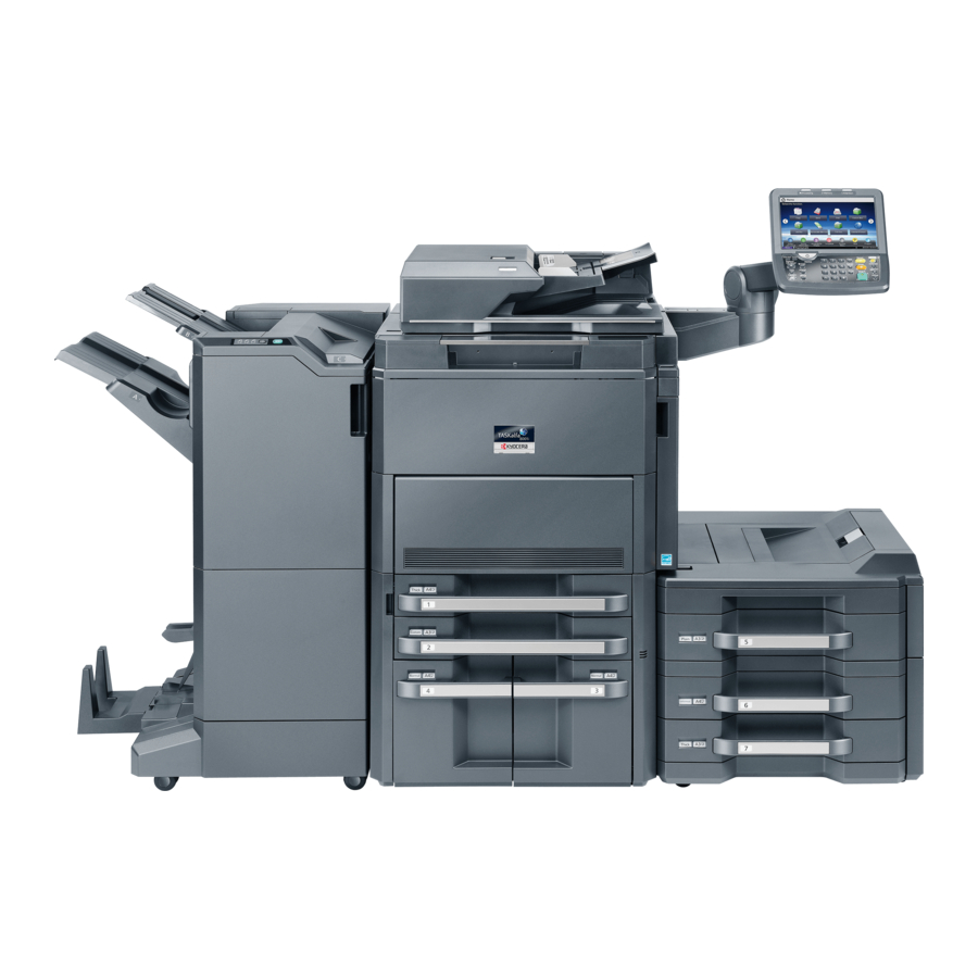
2N8/2N7 1-1-2 Parts names (1) Machine 17 18 Figure 1-1-1 1. Document processor 11. Waste toner box 2. Operation panel 12. Release button 3. Original size indicator plate 13. Handles 4. Platen (Contact glass) 14. Left lower tray 5. Slit glass 15. - Page 27 2N8/2N7 Figure 1-1-2 20. Cassette 1 32. Duplex cover 21. Cassette 2 33. Duplex cover lever 22. Cassette 3 34. MP paper width guides 23. Cassette 4 35. MP support Tray 24. Paper length guide 36. MP (Multi-Purpose) tray 25. Guide lock lever 37.
- Page 28 2N8/2N7-2 (2) Option Figure 1-1-3 1. Machine 5. Side deck 2. Side multi tray Cassette 5 Cassette 5 6. 4000-sheet finisher 3. Side paper feeder 7. Center-folding unit a: Cassette 6 8. Mailbox b: Cassette 7 9. Punch unit 4. Side large capacity feeder 10.
- Page 29 2N8/2N7-4 Figure 1-1-4 11. Printed document guard kit 18. Key counter Software option 12. Keyboard holder 1. Data Security Kit 13. IC card reader holder 2. Internet FAX Kit 14. Expansion memory for Fax 3. Card Authentication Kit 15. Fax kit 4.
- Page 30 2N8/2N7 (3) Operation panel Figure 1-1-5 1. Status/Job cancel key 10. Main power indicator 19. Interrupt key 2. System menu key 11. Help key 20. Authentication/Logout key 3. Counter key 12. Accessibility display key 21. Energy saver key 4. Copy key 13.
- Page 31 2N8/2N7 1-1-3 Machine cross section (1) Machine Figure 1-1-6 1. Paper feed section 5. Optical section 11. Fuser section (cassette 1, 2) 6. Laser scanner unit 12. Feed shift/Switchback 2. Paper feed section 7. Drum unit sections (cassette 3, 4) 8.
- Page 32 2N8/2N7 (2) Document processor Original path Figure 1-1-7 1. Original feed section 2. Original conveying section 3. Original eject section 1-1-16...
-
Page 33: Installation Environment
2N8/2N7-4 1-2 Installation 1-2-1 Installation environment 1. Temperature: 10 to 32.5°C/50 to 90.5°F (But humidity should be 70% or less when temperature is 90.5 °F (32.5 °C).) 2. Humidity: 15 to 80% RH (But temperature should be 86 °F (30 °C) or less when humidity is 80%.) *: Use coated paper at a temperature of 80.6 °F (27°C) or less and a humidity of 60% or less. - Page 34 2N8/2N7 6. Allow sufficient access for proper operation and maintenance of the machine. Machine front : 100 cm/39 3/8" Machine rear : 10 cm/ 3 15/16" Machine right : 35 cm/13 3/4" Machine left : 30 cm/11 13/16" Machine top : 40 cm/15 3/4" 10cm/3 15/16"...
-
Page 35: Unpacking And Installation 1
2N8/2N7-1 1-2-2 Unpacking and installation (1) Installation procedure Start Replacing operation panel sheet Unpacking Taking out the machine Installing other optional devices Removing the tapes and spacers Installing the stoppers Installing the cassette heater (option) Installing the operation arm Connect the power cord Release the lock of the scanner mirror frame Setup for adjusting images Release of lift plate stopper (cassette 1 and 2) - Page 36 2N8/2N7 Moving the machine When moving the machine, pull out the carrying handle, and move with the carrying handle and three hand- holds. Handhold Handhold Handhold Carrying handle (Handhold at the right front) Figure 1-2-2 *: Use the handhold at the right front only <Allowable angle of the right The handhold at the right front side front handhold positions>...
- Page 37 2N8/2N7-2 Unpacking 26 27 17,18,19 20,21 Figure 1-2-4 1. Machine 11. Right stays 21. Operation guide etc. 2. Outer case 12. Machine cover 22. Toner disposal box case 3. Inner case 13. Bottom spacer 23. Air-padded bag 4. Skid 14. Operation arm 24.
- Page 38 2N8/2N7 Operation arm Figure 1-2-5 1. Arm outer case 8. Operation mount cover A 15. Stopper case 2. Arm bottom spacer 9. Operation mount cover B 16. Plastic bags 3. Arm main pad 10. Arm hinge cover A 17. Stoppers 4.
- Page 39 2N8/2N7 Taking out the machine *: When taking out the machine, a space for machine rear requires approximately 2 m. 1. Remove the hinge joints, and then remove the outer case, the inner case, the top left/right pads, the left/right stays, the front pad, the upper spacer, the operation arm and the bottom spacer.
- Page 40 2N8/2N7 5. Check that there is no level difference in slopes (circle section of figure 1-2-7). 6. Open the machine cover. 7. Lift the machine each left and right one side, and then remove the bottom left and right pads and machine cover. Bottom right pad Slope Bottom left pad...
- Page 41 2N8/2N7 Removing the tapes and spacers 1. Remove five tapes and then remove the Tape sheet. Top sheet Tape Tape Tape Tape Figure 1-2-10 2. Remove five tapes. Tape Tape Tape Tape Tape Figure 1-2-11 1-2-9...
- Page 42 2N8/2N7 Original width guide 3. Open the original width guides and then remove the spacer. Original width guide Spacer Figure 1-2-12 4. Remove fourteen tapes, silica gel and Tape sheet. Tape Silica gel Tape Tape Tape Tape Tape Tape Tape Tape Tape Sheet...
- Page 43 2N8/2N7 5. Remove six tapes and then remove three protect sheets. Protect sheet Tapes Tapes Protect sheet Figure 1-2-14 Tape 6. Open the DP. 7. Remove four tapes and then remove the sheet. Tape 8. Remove the tape and then remove A2 Sheet papers.
- Page 44 2N8/2N7-2 10. Open the front upper cover. Spacer 11. Remove two tapes and then remove two spacers 12. Close the front upper cover. Spacer Tape Tape Tapes Front upper cover Figure 1-2-16 120V model only 13. Pull cassette 1 out. 14.
- Page 45 2N8/2N7 2. Insert two hooks and the install the operation arm to the machine. Hooks *: Install the unit observing the caution not to damage the wires. Operation arm Figure 1-2-19 Upper side Positioning 3. Align the two positioning keys with each other, fix the operation arm using four M4x8 screws a top and two M4x8 screws from the right side.
- Page 46 2N8/2N7 4. Connect four connectors of the opera- Connector tion arm to connectors of the machine. 5. Pass the wire through the wire saddle and then fasten the wire. Connector Connector Connector Wire saddle Figure 1-2-21 6. Fit the operation mount cover A and B using two M4 x 8 screws (black).
- Page 47 2N8/2N7 7. Fit the arm hinge cover A and B using the M4 x 8 screws (black). Arm hinge cover B Arm hinge cover A Screw Figure 1-2-23 8. Fit the operation mount cover C using the M4 x 8 screws (black). Screw Operation mount cover C...
- Page 48 2N8/2N7 Release the lock of the scanner mirror frame 1. Open the DP. 1. Remove the tape and then remove the ISU lock leaflet. 2. Remove the scanner lock cover. 3. Mount the scanner lock cover in the reverse manner to restore in the original location.
- Page 49 2N8/2N7 Release of lift plate stopper (cassette 1 and 2) 1. Pull cassette 1 and 2 out. 2. Remove the lift plate stopper from each cassette and attach it to the storage location. *: When moving the machine, attach the lift plate in original position.
- Page 50 2N8/2N7 2. Press the guide lock lever to release the lock. 3. Grasp the paper width adjusting tab and move the paper width guides to fit the paper. Guide lock lever Paper width Paper width guides adjusting tab Figure 1-2-28 4.
- Page 51 2N8/2N7 5. Press the guide lock lever to lock. Guide lock lever Figure 1-2-30 6. Insert the paper size plate and the Paper media plate paper media plate. 7. Gently push the cassette back in. Paper size plate Figure 1-2-31 1-2-19...
- Page 52 2N8/2N7 Release of lift plate stopper (cassette 3 and 4) 1. Pull cassette 3 and 4 out. 2. Remove the lift plate stopper from each cassette and attach it to the storage location. *: When moving the machine, attach the lift Lift plate plate in original position.
- Page 53 2N8/2N7 2. Insert the paper size guide A into the Lock lever slot (bottom of cassette) for the paper size to be used. 3. Make sure that the top of the paper size guide A matches the paper size to be used, attach the lock lever, and rotate the lever to lock it.
- Page 54 2N8/2N7 5. Adjust the paper size guide B to the [A4] paper size. Insert the paper size guide B into the slot marked A4 (on the bottom of the cassette), and lock the hook. Gently try moving the paper size guide B to verify that it is fixed.
- Page 55 2N8/2N7 6. Align the paper flush against the right Paper side of the cassette. *: Before loading the paper, be sure that it is not curled or folded. *: Ensure that the loaded paper does not exceed the level indicated. Figure 1-2-37 7.
- Page 56 2N8/2N7 Installing the toner containers 1. Open the front upper cover. 2. Hold the toner container vertically and hit the upper part about 5 times. Invert the toner container so that the other end is up, and hit in the same way. 3.
- Page 57 2N8/2N7 Unlocking the developer waste exit Caution To ease setup, the device was shipped Tape with the developer unit already replenished with developer. Therefore, to prevent developer from spilling during shipping, a developer shutter is equipped with the Tape developer unit. To disengage the shutter, use the following Wate toner procedure: Note that if the shutter is not...
- Page 58 2N8/2N7-3 5. Press the fixing pin and rotate. *: Fully insert the fixing pin with keeping the protrusions vertical and rotate it by 90 degrees clockwise. Make sure that the protrusions are then horizontal. [Locked] [Released] Fixing pin Fixing pin Protrusions Protrusions Figure 1-2-43...
- Page 59 2N8/2N7-1 Installing the toner disposal box 1. Remove the tape. 2. Remove the cable cover. Cable cover Tape Toner disposal box Figure 1-2-45 3. Fit the toner disposal box using three M3 x 8 S tight screws. Toner disposal Toner disposal Screws Screw Screw...
- Page 60 2N8/2N7-1 4. Connect the connector. 5. Fit the cable cover using M3 x 8 P tight screw. *: If power is turned on without the toner waste box installed, the C Call is caused. FAN unconnected: C7470 Connectors Cable cover Screw Toner disposal box Figure 1-2-47...
- Page 61 2N8/2N7 2. Remove the clear panel. Clear panel Figure 1-2-49 3. Remove the operation panel sheet. 4. Replace the operation panel sheet of the corresponding language. 5. Refit the clear panel. 6. Refit the operation panel covers A and Operation panel sheet Figure 1-2-50 Installing other optional devices...
- Page 62 2N8/2N7 Installing the stoppers The above is not required when an optional document finisher or the side feeder has been installed. Screws Stopper 1. Fix the stoppers with two screws at the bottom right of the device. *: Use the upper screw holes. Screw Screw Screw...
- Page 63 2N8/2N7-4 Connect the power cord 1. Connect the power cord to the power cord connector on rear lower of the machine. 2. Connect the power plug to the wall out- let. Power cords 120 V specifications Power cord 220 - 240 V specifications Figure 1-2-53 Installing toner 1.
- Page 64 2N8/2N7-5 2. Setup setting at high altitude place. When setup is done at high altitude place, execute as follows (such as in Mexico City). (see page 1-3- 83). U140 -> AC Calib -> Calibration -> Execute -> Start Result: developing leak image occur (see page 1-4-220). U140 - AC Calib ->...
- Page 65 2N8/2N7-4 Enter the maintenance mode by entering 10871087 using the numeric keys. Enter 410 using the numeric keys and press the start key. Press [Normal Mode] and then press the start key. A test patterns 1 and 2 are outputted. Place the output test pattern 1 as the original.
- Page 66 2N8/2N7 (2) Setting initial copy modes Factory settings are as follows: Maintenance Contents Factory setting item No. U253 Switching between double and single counts DBL(A3/Ledger) U260 Selecting the timing for copy counting Eject U285 Setting service status page U323 Setting abnormal temperature and humidity warning U325 Setting the paper interval Off/1...
- Page 67 2N8/2N7-1 1-2-3 Installing the key counter (option) Key counter installation requires the following parts: Parts Quantity Part.No. Key counter 3025418011 Key counter set 302A369709 Key counter wire* 302K946AJ0 Tray mount set 302LF94291 *: Not used in 120V model. Supplied parts of key counter set (302A369709): Parts Quantity Part.No.
- Page 68 2N8/2N7 Procedure 1. Press the power key on the operation Key counter M4 x 6 screw retainer panel to off. Make sure that the power indicator and the memory indicator are M4 x 6 screw off before turning off the main power M3 nut switch.
- Page 69 2N8/2N7 6. Remove the controller cover. 7. Remove the screw and then remove the controller lid. Screw Controller lid Controller cover Figure 1-2-56 1-2-37...
- Page 70 2N8/2N7 8. Release seven wire saddles on the con- Wire holder troller box. Wire saddles Wire saddles 9. Remove three wire holders. Controller box Wire saddle Wire saddles Wire holders Figure 1-2-57 1-2-38...
- Page 71 2N8/2N7 10. Remove the connector from the DP relay PWB, 11. Remove the following connectors that connected to the main PWB from the outside of the control box. YC25 YC11 YC30 YC42 YC43 (FFC connector with a lock) YC21 (WH) YC22 (WH) YC26 (BK) YC12...
- Page 72 2N8/2N7 12. Remove five screws. 13. Unhook two hooks and then remove the controller box. Controller box Hook Screw Hook Screws Screws Figure 1-2-59 14. Open the DP. Screw Remove the screw and then remove the operation mount cover C. Operation mount cover C Figure 1-2-60...
- Page 73 2N8/2N7 15. Remove the screw and then remove the arm hinge cover A and B. Screw Arm hinge cover B Arm hinge cover A Figure 1-2-61 16. Remove the screw and then remove the Screw operation mount cover A. Operation mount cover A Figure 1-2-62 1-2-41...
- Page 74 2N8/2N7 17. Cut out the aperture plate on the opera- tion mount cover B using nippers. Aperture Operation mount cover B Figure 1-2-63 18. Connect the connector of the key coun- ter wire to the connector YC24 on the engine PWB. Engine PWB Key counter wire YC24...
- Page 75 2N8/2N7 19. Remove two wire holders. 20. Route the key counter wire through the wire guide and fix it at the wire holders. Key counter wire Wire guide Wire holders Figure 1-2-65 21. Route the key counter wire through the three wire saddles and fix it at the wire holder.
- Page 76 2N8/2N7 22. Pass the connector of the key counter Key counter wire wire through the aperture in the opera- tion mount cover B and refit the opera- tion mount cover A. 23. Refit the arm hinge cover A, B and operation mount cover C.
- Page 77 2N8/2N7 27. Fit the tray mount to the operation arm M4 x 20 M4 x 20 using two M4 x 20 tap-tight S screws. tap-tight S tap-tight S screw screw Tray mount Figure 1-2-69 28. Cut out the aperture plate on the tray cover using nippers.
- Page 78 2N8/2N7 30. Fit the key counter cover retainer to the M4 x 20 M4 x 20 tray cover using two M4 x 20 tap-tight S tap-tight S tap-tight S screws. screw screw Key counter cover retainer Figure 1-2-71 31. Connect the key counter signal cable to Key counter cover M4 x 6 screw the key counter wire.
- Page 79 2N8/2N7-1 1-2-4 Installing the key card MK-2 (option for Japan only) Key card installation requires the following parts: Parts Quantity Part.No. Key card MK-2 8J272002 (option) MK-2 mount Supplied with MK-2 M4 x 16 screw Tray mount set 302LF94291 Supplied parts of tray mount set (302LF94291): Parts Quantity Part.No.
- Page 80 2N8/2N7 3. Remove the controller cover. 4. Remove the screw and then remove the controller lid. Screw Controller lid Controller cover Figure 1-2-74 1-2-48...
- Page 81 2N8/2N7 5. Release seven wire saddles on the con- Wire holder troller box. Wire saddles Wire saddles 6. Remove three wire holders. Controller box Wire saddle Wire saddles Wire holders Figure 1-2-75 1-2-49...
- Page 82 2N8/2N7 7. Remove the connector from the DP relay PWB, 8. Remove the following connectors that connected to the main PWB from the outside of the control box. YC25 YC11 YC30 YC42 YC43 (FFC connector with a lock) YC21 (WH) YC22 (WH) YC26 (BK) YC12...
- Page 83 2N8/2N7 9. Remove five screws. 10. Unhook two hooks and then remove the controller box. Controller box Hook Screw Hook Screws Screws Figure 1-2-77 11. Open the DP. Screw Remove the screw and then remove the operation mount cover C. Operation mount cover C Figure 1-2-78...
- Page 84 2N8/2N7 12. Cut out the aperture plate on the opera- tion mount cover C using nippers. Aperture Operation mount cover C Figure 1-2-79 13. Pass the MK-2 signal cable through the aperture in the operation mount cover Aperture MK-2 signal cable Figure 1-2-80 1-2-52...
- Page 85 2N8/2N7 14. Connect the connector of the MK-2 sig- nal cable to the connector YC25 on the engine PWB. Ground terminal 15. Remove the screw from the machine. 16. Fix the MK-2 signal cable to the ground terminal with the screw that was Screw removed.
- Page 86 2N8/2N7 17. Remove two wire holders. 18. Route the MK-2 signal cable through the wire guide and fix it at two wire hold- ers. 19. Refit the operation mount cover C. 20. Refit the controller box. 21. Refit the rear upper cover. MK-2 signal cable Wire guide Wire holders...
- Page 87 2N8/2N7 23. Fit the tray mount to the operation arm M4 x 20 M4 x 20 using two M4 x 20 tap-tight S screws. tap-tight S tap-tight S screw screw Tray mount Figure 1-2-84 24. Fit the tray cover to the tray mount M4 x 8 screw using two M4 x 8 screws.
- Page 88 2N8/2N7 25. Remove the four screws securing the MK-2 cover; attach the MK-2 mount to the MK-2, and secure using the four MK-2 screws. Screws Screws MK-2 Screws MK-2 mount Screws Figure 1-2-86 26. Fit the MK-2 to the tray cover using two M4 x 20 tap-tight S M4 x 20 tap-tight S screws.
- Page 89 2N8/2N7 1-2-5 Installing the KMAS (option for Japan only) KMAS installation requires the following parts: Using the PHS module Parts Quantity Part.No. PHS module HM000080 (option) PHS signal cable 023CK200 (option) KMAS interface PWB 023CK000 (option) M3 x 16 bronze binding screw B3323160 Ferrite core 2A027770...
- Page 90 2N8/2N7 Procedure To fix KMAS, perform the following procedure: Start Setting the DIP switch Fitting the KMAS interface PWB Using the PHS module Using a modem Fitting the PHS signal cable Fitting the RS-232C signal cable and PHS module Initializing the KMAS 1-2-58...
- Page 91 2N8/2N7 Setting the DIP switch 1. Configure DIP switches 1 to 4 on the KMAS interface board as follows: DIP switch Figure 1-2-88 DIP SW No. Description Remarks PHS module/modem switching ON: Use modem OFF: Use PHS module Modem outgoing switching This is required when modem is used.
- Page 92 2N8/2N7 Fitting the KMAS interface PWB 2. Remove nine screws and then remove the rear upper cover. *: To fix a cover, insert the hook at the left top first by bowing the cover. Hook Rear upper cover Screws Screws Screws Screws Figure 1-2-89...
- Page 93 2N8/2N7 4. Insert the KMAS interface PWB to three Spacer B spacers B. Spacer B Spacer B KMAS interface PWB Figure 1-2-91 1-2-61...
- Page 94 2N8/2N7 5. Connect the connector of the KMAS wire to the connector YC1 on the KMAS PWB. 6. Connect the connector of the KMAS wire to controller fan motor, YC7 on the main PWB. KMAS wire KMAS interface PWB Main PWB KMAS wire Controller fan motor Figure 1-2-92...
- Page 95 2N8/2N7 7. Pass the KMAS wire through the edging of the controller box and wire saddle and then fasten the KMAS wire. Edging KMAS wire Wire saddle Figure 1-2-93 Fitting the PHS signal cable and PHS mod- Rear upper cover 8.
- Page 96 2N8/2N7 11. Connect the connector of the PHS sig- nal cable to the connector YC2 on the KMAS KMAS interface PWB. interface PWB 12. Refit the rear upper cover. PHS signal cable Figure 1-2-95 13. Fit the PHS module to rear upper cover using two M3 x 16 screws.
- Page 97 2N8/2N7 14. Wrap the PHS signal cable around the ferrite core a turn. 15. Connect the connector of the PHS sig- nal cable to PHS module. 16. Fit the clamp to PHS signal cable. PHS module 17. After using alcohol to clean the rear upper cover, adhere the clamp to rear upper cover.
- Page 98 2N8/2N7 1-2-6 Installing the coin vender (option for japan only) Coin vender installation requires the following parts: Parts Quantity Part.No. 1905H99JP0 (option) Coin vender Vender wire Vender base Supplied with M4 x 6 screw coin vender Ferrite core Clamp Vender signal cable 302K946AE0 Procedure 1.
- Page 99 2N8/2N7 3. Remove nine screws and then remove the rear upper cover. *: To fix a cover, insert the hook at the left top first by bowing the cover. Hook Rear upper cover Screws Screws Screws Screws Figure 1-2-99 4. Cover the area under the toner disposal box to prevent contamination due to the scattered toner.
- Page 100 2N8/2N7 Toner 7. Remove three screws and then remove disposal box the toner disposal box. Toner Screws disposal box Screw Screw Screw Screw Figure 1-2-101 8. Remove nine screws. 9. Release two hanging parts and then remove the rear lower cover. Screw Screw Screws...
- Page 101 2N8/2N7 10. Remove two screws and then remove the lid. Screws Figure 1-2-103 YC23 Engine PWB 11. Connect the connector of the vender signal cable to the connector YC23 on the engine PWB. 12. Pass the vender signal cable through the wire guide and nine wire saddles and then fasten the cable.
- Page 102 2N8/2N7 13. Pass the vender wire through the aper- ture in the IF mount. 14. Secure the vender wire with two screws Ground removed in step 10. terminal 15. Secure the ground terminal of the vender wire to rear frame with the screw.
- Page 103 2N8/2N7 19. Fit the ferrite core to signal cable of coin vender. Coin vender 20. Fit the clamp to signal cable of coin vender. 21. Remove a screw from the coin vender Clamp and fix the coin vender with a clamp. Screw Ferrite core Signal cable...
- Page 104 2N8/2N7 1-2-7 Installing the cassette heater (option) Cassette heater installation requires the following parts: 120 V specifications Parts Quantity Part.No. Cassette heater set 302K994931 (for cassette 1 and 2) Cassette heater set 303NF94130 (for cassette 3 and 4) Supplied parts of cassette heater set (302K994931): Parts Quantity Part.No.
- Page 105 2N8/2N7 220 - 240 V specifications Parts Quantity Part.No. Cassette heater set 240V 302K994941 (for cassette 1 and 2) Cassette heater set 240V 303NF94140 (for cassette 3 and 4) Supplied parts of cassette heater set (302K994941): Parts Quantity Part.No. Cassette heater 240V 302H794610 Wire saddle 7YZM610001++H01...
- Page 106 2N8/2N7-1 Procedure Installing for cassette 1 and 2 Cassette 1. Press the power key on the operation panel to off. Make sure that the power indicator and the memory indicator are off before turning off the main power switch. And then unplug the power cable from the wall outlet.
- Page 107 2N8/2N7-7 5. Fit three wire saddles on the bottom frame of the machine. 6. Fit the cassette heater using two M3 x 8 screws. Wire saddles Screw Screw Cassette heater Figure 1-2-111 1-2-75...
- Page 108 2N8/2N7-7 7. Pass the wire of the cassette heater through three wire saddles and then fasten the wire. *: Route the wire so that it do not disturb opening and closing the cassettes. 8. Connect the connector of the cassette Connector heater to the connector in the rear frame of the machine.
- Page 109 2N8/2N7-7 11. Adhere the caution label after wiping the bottom frame of this side of cassette heater with alcohol. Caution label Figure 1-2-114 *: Perform the maintenance mode U327 to configure the cassette heater control settings after a cassette heater was installed. 1-2-77...
- Page 110 2N8/2N7 Installing for cassette 3 and 4 1. Pull the cassette 3 forward. 2. Remove the four screws and then remove the cassette 3. Cassette 3 Screw Screw Screw Screw Figure 1-2-115 3. Pull the cassette 4 forward. 4. Remove the four screws and then Cassette 4 remove the cassette 4.
- Page 111 2N8/2N7 5. Fit three wire saddles on the bottom frame of the machine. 6. Fit the cassette heater using two M3 x 8 screws. Wire saddles Screw Screw Cassette heater Figure 1-2-117 7. Pass the wire of the cassette heater through three wire saddles and then Connector fasten the wire.
- Page 112 2N8/2N7 9. Insert two hooks of the connector cover to the holes of base of the machine each. 10. Install the connector cover by using a M4 x 8 screw. Connector cover Screw Hook Hook Figure 1-2-119 11. Adhere the caution label after wiping the bottom frame of this side of cassette heater with alcohol.
- Page 113 2N8/2N7 1-2-8 Installing the gigabit ethernet board (option) Gigabit ethernet board installation requires the following parts: Parts Quantity Part.No. Gigabit ethernet board 1505JV0UN0 (option) Procedure 1. Press the power key on the operation panel to off. Make sure that the power indicator and the memory indicator are off before turning off the main power switch.
- Page 114 2N8/2N7 4. Insert the gigabit ethernet board along the groove in OPT2 and secure the board with two pins that have been Gigabit removed in step 3. ethernet board *: Do not directly touch the gigabit ethernet board terminal. Hold the top and bottom of the gigabit ethernet board, or the projection of the board to insert the gigabit ethernet board.
- Page 115 2N8/2N7 1-2-9 Installing the Wire-less interface kit (option) Wire-less interface kit installation requires the following parts: Parts Quantity Part.No. Wire-less interface kit 1505J50UN0 (option) Procedure 1. Press the power key on the operation panel to off. Make sure that the power indicator and the memory indicator are off before turning off the main power switch.
- Page 116 2N8/2N7 4. Insert the wire-less interface kit along the groove in OPT2 and secure the board with two pins that have been Wire-less removed in step 2. interface kit *: Do not directly touch the wire-less inter- face kit terminal. Hold the top and bottom of the wire-less interface kit, or the projection of the board to insert the wire-less interface kit.
- Page 117 2N8/2N7 1-2-10 Installing the IC card reader holder (option) IC card reader holder installation requires the following parts: Parts Quantity Part.No. IC card reader holder (E) 1709AD0UN1 (option) Supplied parts of IC card reader holder (1709AD0UN0): Parts Quantity Part.No. IC card reader holder Label Bundling band Hook and loop fasteners...
- Page 118 2N8/2N7 3. Affix a label on the right table cover Label aligning it with the positioning mark. *: Fix it by matching with a smoke of a dif- Right table cover Positioning mark ferent color. Figure 1-2-129 IC card reader 4.
- Page 119 2N8/2N7 5. Affix two hook and loop fasteners to the IC card reader and IC card reader IC card reader holder holder. Hook and loop fasteners Hook and loop fasteners IC card reader (Type A) 6. Mount the IC card reader to the IC card IC card reader holder reader holder.
- Page 120 2N8/2N7 7. Affix two hook and loop fasteners to the IC card reader and IC card reader IC card reader holder holder. Hook and *: Affix a hook and loop fastener onto the IC loop fasteners card reader so that it is mounted on the holder with both being flush with the right side edges.
- Page 121 2N8/2N7 9. Route the USB cable from the IC card IC card reader holder reader through the IC card reader holder ribs, wind around its back and route through another rib. *: Make sure the cable will have a slack of more than 20 cm.
- Page 122 2N8/2N7 10. Affix two hook and loop fasteners to the IC card reader. IC card reader holder 11. Affix a hook and loop fastener at the reverse side of the spacer where an Spacer adhesive tape has been affixed. Affix two spacers to the IC card reader. Hook and loop fasteners Spacer...
- Page 123 2N8/2N7 13. Route the USB cable from the IC card USB cable reader through the ribs at the bottom of IC card reader holder the IC card reader holder, wind around its back a couple of turns, and route through the rib on the left hand side. Rib (left) USB cable Rib (bottom)
- Page 124 2N8/2N7 14. Reverse the right table cover and snap IC card reader holder the IC card reader holder into the 5 latches to mount. Right table cover Holes Holes Figure 1-2-136 15. Connect the USB cable with the USB connector on the machine. USB connector USB cable Figure 1-2-137...
- Page 125 2N8/2N7 16. Fix the right table cover by using the screw which was removed in step 2. *: Use care not to pinch the wire. Right table cover Screw Figure 1-2-138 Enabling IC Card Authentication Precautions To install the optional function, you need the License Key. Please access the designated website of your dealer or service representative, and register “Machine No.”...
- Page 126 2N8/2N7-2 1-2-11 Installing the keyboard holder (option) Keyboard holder installation requires the following parts: Parts Quantity Part.No. Keyboard holder (C) 1709AF0UN2 (option) Supplied parts of keyboard holder (C) (1709AF0UN2): Parts Quantity Part.No. Keyboard mounting bracket Keyboard base Hook and loop fasteners A Hook and loop fasteners B Right keyboard lock Left keyboard lock...
- Page 127 2N8/2N7-2 3. Remove a screw and then remove the left table cover. *: While holding the cover at its far end, slide it leftwards to remove. 4. Secure the M4×25 screw. 5. Refit the right table cover and left table cover.
- Page 128 2N8/2N7 8. Using a flat-blade screwdriver, lever open the right and left lids to remove. Groove Groove left lid Right lid Figure 1-2-142 9. Un mount the keyboard base from the Keyboard mounting bracket keyboard mounting bracket. Keyboard base Figure 1-2-143 1-2-96...
- Page 129 2N8/2N7 10. Align the keyboard mounting bracket with the main unit at its positioning Keyboard mounting boss, secure it using two M4×8 screws. bracket M4×8 screws Positioning boss Figure 1-2-144 11. Remove two screws and then remove Screw the keyboard cover from the keyboard keyboard cover base.
- Page 130 2N8/2N7 12. Lift the protrusions of the film off of the Hole Film hold. Protrusion part Unhook at two holes and remove the film from the keyboard base. Hole Hook Hook keyboard base Figure 1-2-146 13. Connect the USB cable with the USB Keyboard connector on the machine.
- Page 131 2N8/2N7 14. Attach the keyboard base to a keyboard Keyboard mounting bracket mounting bracket. *: Insert the keyboard askew so that the Roller roller on the keyboard base is positioned between the guide of the keyboard mounting bracket and the roller. Roller keyboard base Figure 1-2-148...
- Page 132 2N8/2N7 16. Draw out the keyboard base. 17. With the USB cable strained slightly loose, fix a band to the wire and fix the Keyboard base band to the hole on the keyboard. Band Hole USB cable Figure 1-2-150 18. Bundle the remaining portion of the USB wire and recess under the key- USB cable board base.
- Page 133 2N8/2N7 19. Replace the film which was removed in Protrusion B Hole step 7 to the keyboard base. 1) Insert the protrusions A (3) in the Film chase of the keyboard base. 2) Mate the holes (2) with the hooks of the keyboard base.
- Page 134 2N8/2N7 20. Attach the keyboard cover to a key- Screw Keyboard cover board base with two screws that have Screw been removed in step 6. *: Route the keyboard USB wire through the opening in the keyboard cover. Keyboard base USB cable Opening Figure 1-2-153...
- Page 135 2N8/2N7-1 23. Align the keyboard with the hook and Keyboard loop fasteners and fix on the keyboard base. Keyboard base Figure 1-2-155 24. If the USB cable from keyboard runs off of the keyboard, dress it into the key- board base. 25.
- Page 136 2N8/2N7-3 1-2-12 Installing the Printed Document Guard Kit (option) Printed Document Guard Kit installation requires the following parts: Parts Quantity Part.No. Printed Document Guard Kit (B) 1503P40UN0 Supplied parts of Printed Document Guard Kit: Parts Quantity Part.No. Copy guard PWB FFC (short) FFC (long)* Mount plate B*1...
- Page 137 2N8/2N7 3. Insert the FFC into the copy guard PWB YC2 (serigraphed on MAIN) YC1 (serigraphed on DP) Copy Guard PWB YC2(MAIN) YC1(DP) Figure 1-2-158 Main PWB 4. Insert the copy guard PWB to the side of the main PWB and fix with a S Tite screw M4 x 8.
- Page 138 2N8/2N7 Figure 1-2-159 5. Connect the main PWB and the DP Main PWB YC34 relay PWB with the FFC. Main PWB YC34 DP relay PWB YC35 DP relay PWB YC35 Figure 1-2-160 6. Replace the upper rear cover. 7. Confirm the settings. 1) Turn the main power switch on.
- Page 139 2N8/2N7 1-2-13 Installing the handset (option for Japan only) Handset installation requires the following parts: Parts Quantity Part.No. Handset 1909AG9JP0 (option) Supplied parts of handset (1909AG9JP0): Parts Quantity Part.No. Handset Handset base Handset mount Protection cover Telephone wire Modular cable M4 nut 3CY06030 1-2-107...
- Page 140 2N8/2N7 Procedure 1. Press the power key on the operation panel to off. Make sure that the power indicator and the memory indicator are off before turning off the main power switch. And then unplug the power cable from the wall outlet. 2.
- Page 141 2N8/2N7 6. Mount two M4 nuts at the back of the ISU rear cover. ISU rear cover 7. Fit the handset mount to the ISU rear cover using two pins. *: Use the lower screw holes. Handset mount M4 nuts Pins Pins Figure 1-2-163...
- Page 142 2N8/2N7 12. Insert the pins at the insert parts on the back of the handset base, and slide it towards you. Handset base Figure 1-2-165 1-2-110...
- Page 143 2N8/2N7 13. Fit the protection cover to the handset mount. Protection cover Handset mount Figure 1-2-166 14. Connect the telephone wire to the handset and the handset base. Handset Handset base Telephone wire Figure 1-2-167 1-2-111...
- Page 144 2N8/2N7 15. Connect the modular cable to the hand- set base and the machine. Modular cable Handset base Modular cable Figure 1-2-168 1-2-112...
-
Page 145: Optional Applications
2N8/2N7-2 1-2-14 Optional Applications Overview of the Applications The applications listed below are installed on this machine. Applications INstall page Data Security Kit page 1-2-114 Internet FAX Kit page 1-2-115 Card Authentication Kit* page 1-2-119 ThinPrint Option (UG-33)* page 1-2-120 Emulation Upgrade Kit (UG-34) page 1-2-121 *: This can be used on a trial basis for a limited time. - Page 146 2N8/2N7-2 (1) Data Security Kit The Data Security Kit overwrites all unnecessary data in the storage area of the hard disk so that it cannot be retrieved. The Data Security Kit encrypts data before storing it in the hard disk. It guarantees higher security because no data cannot be decoded by ordinary output or operations.
- Page 147 2N8/2N7-2 (2) Internet FAX Kit Activating the Internet FAX Kit sends and receives faxes via the Internet without using a phone line. It can only be added when the FAX Kit is installed. *: To install the optional function, you need the License Key. Issue of License Key requires the "Machine No"...
- Page 148 2N8/2N7-2 i-FAX Default Settings Use this page to enable the internet faxing. The settings available on the page are shown below. Item Description Common Transmis Local FAX Name Enter the local fax name. Settings sion TTI Selects On or Off whether to send the TTI (Transmit Terminal Identifier) information to the other party.
- Page 149 2N8/2N7-2 Item Description i-FAX SMTP SMTP Port Number Set the port number used by SMTP. Normally, 25 is used. Settings SMTP Server Timeout Enter the timeout period in seconds. Authentication Protocol Specify whether SMTP authentication will be used or whether [POP before SMTP] will be used. This SMTP authentication is compatible with Microsoft Exchange 2000.
- Page 150 2N8/2N7-2 Item Description i-FAX POP3 Test Runs a test to determine whether the settings specified in Settings this page are correct. E-mail Size Limit Enter the maximum size for E-mails that can be received in kilobytes. You can set up to 32,767 kilobytes. If 0 is entered, the setting does not limit the maximum size.
- Page 151 2N8/2N7-2 (3) Card Authentication Kit This prevents the unauthorized copying and/or transmission of documents that contain important confidential or personal information. When a document is printed from a computer, this feature imprints a special pattern on the document. When anyone attempts to copy or send that document on this machine, the machine detects the pattern and protects the information by printing the document in blank and prohibiting transmis- sion.
- Page 152 2N8/2N7-2 To register on the computer The ID Register utility for registering/deleting ID card information on the computer is provided. You can download the ID Register utility from the vendor’s website. (4) ThinPrint Option This application allows print data to be printed directly without a print driver. *: To install the optional function, you need the License Key.
- Page 153 2N8/2N7-2 (5) Emulation Upgrade Kit Enables emulation whereby the machine operates using commands for other printers. Installing this option enables IBM Proprinter, Line Printer, and EPSON LQ-850 emulation. *: To install the optional function, you need the License Key. Issue of License Key requires the "Machine No" indicated on your machine, and "product ID." Installation Procedure 1.
- Page 154 2N8/2N7 This page is intentionally left blank. 1-2-122...
- Page 155 2N8/2N7 1-3 Maintenance Mode 1-3-1 Maintenance mode The machine is equipped with a maintenance function which can be used to maintain and service the machine. (1) Executing a maintenance item Start Enter “10871087” using Maintenance mode is entered. the numeric keys. Enter the maintenance item number using the cursor up/down keys The maintenance item is selected.
- Page 156 2N8/2N7-4 (2) Maintenance modes item list Initial setting Item Section Content of maintenance item 65ppm 80ppm General U000 Output Maintenance Report U001 Exiting the maintenance mode U002 Setting the factory default data U003 Setting the service telephone number U004 Setting the machine number U010 Setting the maintenance mode ID U018 Check Firmware Checksum U019 Firmware Version...
- Page 157 2N8/2N7 Initial setting Item Section Content of maintenance item 65ppm 80ppm Drive, U053 Motor3 54/-26/93/57/ 42/-21/72/45/ paper 57/79/54/87/ 45/62/43/69/ feed and -8/-8/0/0/0/0 -6/-6/0/0/0/0 paper Motor1 Half convey- Motor2 Half 1626/32/29 1278/25/23 ing sys- Motor3 Half 109/-53/186/115/115/ 85/-41/144/90/90/ 159/108/174/-8/-8 124/85/137/ -6/-6 U059 Setting fan mode Fan Mode Mode1...
- Page 158 2N8/2N7 Initial setting Item Section Content of maintenance item 65ppm 80ppm High U106 Setting the voltage for the secondary voltage transfer Light/Normal 1st 152/147/141 162/159/151 Light/Normal 2nd 141/135/125 153/144/132 Normal2/3 1st 152/147/141 162/159/151 Normal2/3 2nd 141/135/125 153/144/132 Heavy1-3 1st Half 121/121/118 126/126/122 Heavy1-3 2nd Half...
- Page 159 2N8/2N7-3 Initial setting Item Section Content of maintenance item 65ppm 80ppm Developer U140 Magnification Mode1 High Altitude Image Preference Copy Lead Density U147 Setting for toner applying operation 65/8 80/8 Timing Mode1 Mode Upper Limit Minimum U148 Setting drum refresh mode Normal Dew Condensation U155 Checking sensors for toner...
- Page 160 2N8/2N7 Initial setting Item Section Content of maintenance item 65ppm 80ppm Operation U204 Setting the presence or absence of a Off/Coin Vender panel and key card or key counter support U206 Setting the presence or absence of a equip- coin vender ment On/Off Config No Coin Action...
- Page 161 2N8/2N7 Initial setting Item Section Content of maintenance item 65ppm 80ppm ― Mode U252 Setting the destination setting DBL(A3/Ledger) U253 Switching between double and single counts Eject U260 Selecting the timing for copy counting ― U265 Setting OEM purchaser code U271 Setting the page count ―...
- Page 162 2N8/2N7-4 Initial setting Item Section Content of maintenance item 65ppm 80ppm ― Image U425 Setting the target process- U460 Adjusting the conveying sensor U464 Setting the ID correction operation Permission Time Interval Normal Mode On/Sleep Out AP/NE Leaving Time Driving Time Timing Target Value 145/330...
- Page 163 2N8/2N7 Initial setting Item Section Content of maintenance item 65ppm 80ppm Others U920 Checking the copy counts U927 Clearing the all copy counts and machine life counts (one time only) U928 Checking machine life counts U930 Checking/clearing the charger roller count U933 Set Maintenance Mode Execute Log U935 Relay board maintenance...
-
Page 164: Contents Of The Maintenance Mode Items 1
2N8/2N7 (3) Contents of the maintenance mode items Item No. Description U000 Output Maintenance Report Description Outputs lists of the current settings of the maintenance items, and paper jam and service call occurrences. Outputs the event log or service status page. Also sends output data to the USB memory. - Page 165 2N8/2N7 Item No. Description U000 Method: Send to the USB memory 1. Press the power key on the operation panel, and after verifying the main power indicator has gone off, switch off the main power switch. 2. Insert USB memory in USB memory slot. 3.
-
Page 166: Event Log
2N8/2N7 Item No. Description U000 Event log Event Log 2013/01/31 08:40 Firmware version 2N7_2000.000.000 2013.01.27 [XXXXXXXX] [XXXXXXXX] [XXXXXXXX] [XXXXXXXX] (12) Paper Jam Log Counter Log Count. Event Descriprions Date and Time J0000: J0527: C0030: 9999999 0501.01.08.01.01 2013/01/23 11:56 J0100: J0533: C0070: 8888888 4002.01.08.01.01... - Page 167 2N8/2N7 Item No. Description U000 Detail of event log Items Description Controller BROM version Operation panel mask version Machine serial number Paper Jam Count. Event Descriptions Remembers 1 to 16 of The total page count Log code (hexadeci- occurrence. If the occur- at the time of the mal, 5 categories) rence of the previous...
- Page 168 2N8/2N7 Item No. Description U000 Items Description Paper Jam (d) Detail of paper type (Hexadecimal) cont. 01: Plain 0A: Color 15: Custom 1 02: Transparency 0B: Prepunched 16: Custom 2 03: Preprinted 0C: Envelope 17: Custom 3 04: Labels 0D: Cardstock 18: Custom 4 05: Bond 0E: Coated...
- Page 169 2N8/2N7 Item No. Description U000 Items Description Service Call Count. Service Code Remembers 1 to 8 The total page Self diagnostic error code of occurrence of self count at the time of (See page 1-4-60) diagnostics error. If the self diagnostics the occurrence of error.
- Page 170 2N8/2N7 Item No. Description U000 Items Description (11) Unknown Toner Count. Item Remembers 1 to 5 The total page count Unknown toner log of occurrence of at the time of the code unknown toner toner empty error (1 byte, 2 categories) detection.
-
Page 171: Service Status Page
2N8/2N7 Item No. Description U000 Service status page (1) Service Status Page 2012/10/27 12:00 Firmware version 2N7_2000.000.000 2012.10.27 [XXXXXXXX] [XXXXXXXX] [XXXXXXXX] Controller Information (30) FAX Information Slot1/Slot2 (31) Rings (Normal) Memory status (32) Rings (FAX/TEL) Total Size 2.0 GB (33) Rings (TAD) (34) Option DIMM Size... - Page 172 2N8/2N7-6 Item No. Description U000 Service status page (2) Service Status Page 2012/10/27 12:00 Firmware version 2N7_2000.000.000 2012.10.27 [XXXXXXXX] [XXXXXXXX] [XXXXXXXX] Engine Information Send Information (40) (44) NVRAM Version _1F31225_1F31225 Date and Time 10/10/27 15:30 (41) (45) Scanner Version 2N2_1200.001.089 Address mail@bjd.ne.jp (42)
- Page 173 2N8/2N7 Item No. Description U000 Detail of service status page Description Supplement Firmware version System date Engine soft version Engine boot version Operation panel mask version Machine serial number Total memory size Local time zone Report output date Day/Month/Year hour:minute (10) NTP server name (11)
- Page 174 2N8/2N7 Item No. Description U000 Description Supplement (25) Average coverage for copy Black (26) Average coverage for printer Black (27) Average coverage for fax Black (28) Cleared date and output date (29) Coverage on the final output page (30) Fax kit information This item is printed only when the fax kit is installed.
- Page 175 2N8/2N7 Item No. Description U000 Description Supplement (41) Scanner firmware version (42) Fax firmware version This item is printed only when the fax kit is installed. (43) Mac address (44) The last sent date and time (45) Transmission address (46) Destination information (47) Area information...
- Page 176 2N8/2N7-6 Item No. Description U000 Description Supplement (62) Media type attributes Weight settings Fuser settings 1 to 28 (Not used: 18, 19, 20) 0: Light 0: High * : For details on settings, 1: Normal 1 1: Middle refer to the MDAT com- 2: Normal 2 2: Low mand of the “Prescribe...
- Page 177 2N8/2N7 Item No. Description U000 Description Supplement Code conversion U001 Exiting the maintenance mode Description Exits the maintenance mode and return to the normal copy mode. Purpose To exit the maintenance mode. Method 1. Press the start key. The normal copy mode is entered. U002 Setting the factory default data Description...
- Page 178 2N8/2N7 Item No. Description U003 Setting the service telephone number Description Sets the telephone number to be displayed when a service call code is detected. Purpose To set the telephone number to call service when installing the machine. Setting 1. Press the start key. The keys to enter the number are displayed on the touch panel.
- Page 179 2N8/2N7 Item No. Description U010 Setting the maintenance mode ID Description Sets the maintenance mode ID. Purpose Modify maintenance mode ID for more security. Method 1. Press the start key. Display Description New ID Enter a new 8-digit ID New ID(Reconfirm) Enter a new 8-digit ID (to confirm) Initialize Initialize the ID...
- Page 180 2N8/2N7 Item No. Description U018 If the verified result was incorrect, the following are displayed. Display Description f001 An expected-value file does not exist. f002 Reading the expected-value file failed. f003 Illegal data in the expected-value file (not 64-byte data) s001t Failure to read the checksum The expected value and the checksum do not match.
- Page 181 2N8/2N7-1 Item No. Description U019 Display Description Document processor firmware DP Boot Document processor booting Paper feeder / Large capacity feeder firmware PF1 Boot Paper feeder / Large capacity feeder booting Side PF Side multi tray /Side deck firmware Side PF Boot Side multi tray /Side deck booting SMT SSW Side multi tray multi feed sensor...
- Page 182 2N8/2N7 Item No. Description U021 Memory initializing Description Initializes all settings, except those pertinent to the type of machine, namely each counter setting, service call history and mode setting. Also initializes backup RAM according to region specifica- tion selected in maintenance item U252 Setting the destination. Purpose To return the machine settings to their factory default.
- Page 183 2N8/2N7-5 Item No. Description U024 HDD formatting Description Initializes the hard disk. Purpose To initialize the hard disk when replacing the hard disk after shipping. Caution In addition, the following settings are also initialized by initializing the hard disk. System menu (user login administration, job accounting, address book, one-touch keys and doc- ument box etc.), shortcuts and panel programs When fully formatted, the following pre-installed software are removed.
- Page 184 2N8/2N7 Item No. Description U025 Firmware Update (Security) Description Used to execute FW-Update from the USB flash device while Very High is selected in the Secu- rity Level settings under the System Menu. Purpose Firmware upgrading is initiated by a service person to conduct U025 while a USB flash device is inserted.
- Page 185 2N8/2N7 Item No. Description U026 Pulling Backup Data Description Perform restoring of the backup data.. Purpose Restores the setting values that was backed up in the flash memory from the HDD. Method 1. Press the start key. 2. Press [Execute]. 3.
-
Page 186: Cm/11
2N8/2N7 Item No. Description U030 Checking the operation of the motors Description Drives each motor. Purpose To check the operation of each motor. Method 1. Press the start key. 2. Select the motor to be operated. 3. Press the start key. The operation starts. Display Description Feed... - Page 187 2N8/2N7 Item No. Description U031 Checking switches and sensors for paper conveying Description Displays the on-off status of each paper detection switch or sensor on the paper path. Purpose To check if the switches and sensors for paper conveying operate correctly. Method 1.
- Page 188 2N8/2N7 Item No. Description U032 Checking the operation of the clutches Description Turn each clutch on. Purpose To check the operation of each clutch. Method 1. Press the start key. 2. Select the clutch to be operated. 3. Press the start key. The operation starts. Display Description Feed1...
- Page 189 2N8/2N7 Item No. Description U033 Checking the operation of the solenoids Description Turn each solenoid on. Purpose To check the operation of each solenoid. Method 1. Press the start key. 2. Select the solenoid to be operated.z 3. Press the start key. The operation starts. Display Description Branch Left...
- Page 190 2N8/2N7 Item No. Description U034 Adjusting the print start timing Description Adjusts the leading edge registration or center line. Purpose Make the adjustment if there is a regular error between the leading edges of the copy image and original. Make the adjustment if there is a regular error between the center lines of the copy image and original.
- Page 191 2N8/2N7 Item No. Description U034 Adjustment: Leading edge registration adjustment 1. Press the system menu key. 2. Press the start key to output a test pattern. 3. Press the system menu key. 4. Select the item to be adjusted. [LSU Out Top] Setting Initial Change in...
- Page 192 2N8/2N7 Item No. Description 5. Change the setting value using the cursor +/- or numeric keys. U034 For output example 1, increase the value. For output example 2, decrease the value. Leading edge registration (20 ± 1.0 mm) Correct image Output Output example 1...
- Page 193 2N8/2N7 Item No. Description 5. Change the setting value using the +/- keys or numeric keys. U034 For output example 1, increase the value. For output example 2, decrease the value. Center line of printing (within ± 2.0 mm) Correct image Output Output example 1...
- Page 194 2N8/2N7 Item No. Description U035 Setting the printing area for folio paper Description Changes the printing area for copying on folio paper. Purpose To prevent cropped images on the trailing edge or left/right side of copy paper by setting the actual printing area for folio paper.
- Page 195 2N8/2N7 Item No. Description U037 Checking the operation of the fan motors Description Drives each fan motor. Purpose To check the operation of each fan motor. Method 1. Press the start key. 2. Select the fan motor to be operated. 3.
- Page 196 2N8/2N7-4 Item No. Description U051 Adjusting the deflection in the paper Description Adjusts the deflection in the paper at the registration roller. Purpose Make the adjustment if the leading edge of the copy image is missing or varies randomly, or if the copy paper is Z-folded.
- Page 197 2N8/2N7 Item No. Description 5. Change the setting value using the +/- keys or numeric keys. U051 For output example 1, increase the value. For output example 2, decrease the value. The greater the value, the larger the deflection; the smaller the value, the smaller the deflec- tion.
- Page 198 2N8/2N7 Item No. Description U052 Setting: [Loop Sensor Control] 1. Select the item. 2. Select On or Off. Initial setting Display Description 65ppm 80ppm No.1 Determines whether to attempt a correction in the fuser speed in reference to the transfer-separation speed, over the length of paper from the leading edge to 30mm.
- Page 199 2N8/2N7 Item No. Description U053 Setting the adjustment of the motor speed Description Perform fine adjustment of the speeds of the motors. Purpose Basically, the setting need not be changed. Modify settings by interlock setting only if faulty images occur. Method 1.
- Page 200 2N8/2N7 Item No. Description U053 Setting: [Motor3] 1. Select the item to be adjusted. Initial setting Setting Display Description range 65ppm 80ppm Eject motor (EM) -5000 to 5000 54 Fixing Fuser motor (FUM) -5000 to 5000 -26 Bridge1 BR conveying motor 1 -5000 to 5000 93 (BRCM1) Bridge2...
- Page 201 2N8/2N7 Item No. Description U053 Setting: [Motor3 Half] Select the item to be adjusted. Initial setting Setting Display Description range 65ppm 80ppm Eject motor (EM) in half -5000 to 5000 109 speed Fixing Fuser motor (FUM) in half -5000 to 5000 -53 speed Decal Decal motor (BRDM) in...
- Page 202 2N8/2N7 Item No. Description U059 Setting fan mode Description Specifies mode for developer fan motors. Purpose Handling the lowering density [to suppress thermal stresses owing to the heated toner] Method 1. Press the start key. 2. Select the mode. Display Description Fan Mode Sets threshold temperature at which developer fan motors oper-...
- Page 203 2N8/2N7 Item No. Description U059 Setting: [Interval Cycle] 1. Change the setting value using the +/- keys. Setting Initial Display Description range setting Determines the timing cycle for control- 0 to 10 ling the fan * : This will halt printing and activates the motor (described below) when the print count has reached the reference value multiplied by 1000 during copying continuously.
- Page 204 2N8/2N7 Item No. Description U063 Adjusting the shading position Description Changes the shading position of the scanner. Purpose Used when the white line continue to appear longitudinally on the image after the shading plate is cleaned. This is due to flaws or stains inside the shading plate. To prevent this problem, the shading posi- tion should be changed so that shading is possible without being affected by the flaws or stains.
- Page 205 2N8/2N7 Item No. Description U065 Adjusting the scanner magnification Description Adjusts the magnification of the original scanning. Purpose Make the adjustment if the magnification in the main scanning direction is incorrect. Make the adjustment if the magnification in the auxiliary scanning direction is incorrect. Caution The magnification adjustment along the main scanning direction could cause black streaks depending on the content of the original document.
- Page 206 2N8/2N7 Item No. Description U065 Adjustment: [Sub Scan] 1. Change the setting value using the +/- keys or numeric keys. For copy example 1, increase the value. For copy example 2, decrease the value. Increasing the value makes the image longer, while decreasing the value makes the image shorter.
- Page 207 2N8/2N7 Item No. Description U066 Adjusting the scanner leading edge registration Description Adjusts the scanner leading edge registration of the original scanning. Purpose Make the adjustment if there is a regular error between the leading edges of the copy image and original.
- Page 208 2N8/2N7 Item No. Description U067 Adjusting the scanner center line Description Adjusts the scanner center line of the original scanning. Purpose Make the adjustment if there is a regular error between the center lines of the copy image and original. Adjustment 1.
- Page 209 2N8/2N7 Item No. Description U068 Adjusting the scanning position for originals from the DP Description Adjusts the position for scanning originals from the DP. Perform the test copy at the four scanning positions after adjusting. Purpose Used when the image fogging occurs because the scanning position is not proper when the DP is used.
- Page 210 2N8/2N7 Item No. Description U070 Adjusting the DP magnification Description Adjusts the DP original scanning speed. Purpose Make the adjustment if the magnification is incorrect in the auxiliary scanning direction when the DP is used. Make the adjustment if the magnification is incorrect in the main scanning direction when the CIS is used.
- Page 211 2N8/2N7 Item No. Description U070 Adjustment: [Main Scan] 1. Change the setting value using the +/- keys or numeric keys. For copy example 1, increase the value. For copy example 2, decrease the value. Increasing the setting enlarges the image and decreasing it narrows the image. Copy Original Copy...
- Page 212 2N8/2N7 Item No. Description U071 Adjusting the DP scanning timing Description Adjusts the DP original scanning timing. Purpose Make the adjustment if there is a regular error between the leading or trailing edges of the origi- nal and the copy image when the DP is used. Method 1.
- Page 213 2N8/2N7 Item No. Description U071 Adjustment: Leading edge registration 1. Change the setting value using the +/- keys or numeric keys. For copy example 1, increase the value. For copy example 2, decrease the value. Increasing the value moves the image forward and decreasing the value moves the image backward.
- Page 214 2N8/2N7 Item No. Description U072 Adjusting the DP center line Description Adjusts the scanning start position for the DP original. Purpose Make the adjustment if there is a regular error between the centers of the original and the copy image when the DP is used. Adjustment 1.
- Page 215 2N8/2N7 Item No. Description U073 Checking the scanner operation Description Simulates the scanner operation under the arbitrary conditions. Purpose To check the scanner operation. This is also done to check the accumulation of dust on the slit glass. Method 1. Press the start key. 2.
- Page 216 2N8/2N7 Item No. Description U073 Method: [Home Position] 1. Select [Home Position]. 2. Press the start key. The mirror frame of the scanner moves to the home position. Method: [Dust Check] 1. Select [Dust Check]. 2. Press the start key. The exposure lamp lights. 3.
- Page 217 2N8/2N7 Item No. Description U087 Setting DP reading position modification operation Description The presence or absence of dust is determined by comparing the scan data of the original trailing edge and that taken after the original is conveyed past the DP original scanning position. If dust is identified, the DP original scanning position is adjusted for the following originals.
- Page 218 2N8/2N7 Item No. Description U089 Outputting a MIP-PG pattern Description Selects and outputs the MIP-PG pattern created in the machine. Purpose To check copier status other than scanner when adjusting image printing, using MIP-PG pattern output (with-out scanning). Method 1. Press the start key. 2.
- Page 219 2N8/2N7 Item No. Description U091 Setting the white line correction Description Sets the error detection threshold value for white line correction and displays the count result of abnormal pixels. Purpose To perform when replacing the CIS, DP main PWB or CIS roller. Method 1.
- Page 220 2N8/2N7 Item No. Description U091 How to view test copies blank sheet black band Causes Corrective measures No lines No lines Complete Black lines White lines Dirty CIS roller or CIS Clean CIS roller or CIS glass glass and then perform U091 again Black lines No lines Engine side...
- Page 221 2N8/2N7 Item No. Description U099 Adjusting original size detection Description Checks the operation of the original size detection and sets the sensing threshold value. Purpose Modify the threshold of detection if documents are frequently mal-detected in size after scanning a wholly dark document or a document enclosed with dark objects on edges. Method 1.
- Page 222 2N8/2N7 Item No. Description U099 Setting: [B/W Level1] 1. Select an item to be set. 2. Change the setting value using the +/- keys or numeric keys.l Setting Initial Display Description range setting* Original R1 Original threshold value for color R (near side) 0 to 255 Original R2 Original threshold value for color R (center)
- Page 223 2N8/2N7 Item No. Description U100 Adjusting main high voltage Description Controls the charger roller voltage to optimize the surface potential. Purpose To change the setting value to adjust the image if an image failure (background blur, etc.) occurs. Method 1. Press the start key. 1.
- Page 224 2N8/2N7 Item No. Description U100 Displaying: [Set DC Bias] 1. The current setting is displayed. Display Description DC1 Bias(K) Main charger DC bias for black (full speed) DC1 Bias Half(K) Main charger DC bias for black (half speed) Setting: [Adj DC Bias] 1.
- Page 225 2N8/2N7 Item No. Description U106 Setting the voltage for the secondary transfer Description Sets the control voltage for the secondary transfer depending on each paper type. Purpose To change the setting when any density problems, such as too dark or light, occur. Method 1.
- Page 226 2N8/2N7 Item No. Description [2nd] U106 Initial setting Setting Display Description range 65ppm 80ppm Width=105 105 mm wide 0 to 255 Width=210 210 mm wide 0 to 255 Width=297 297 mm wide 0 to 255 4. Press the start key. The value is set. Setting: [Normal2/3] 1.
- Page 227 2N8/2N7 Item No. Description U106 Setting: [Heavy1-3] 1. Select the item to be set. Display Description 1st Half Control voltage for the transfer bias for the first side (half speed) 2nd Half Control voltage for the transfer bias for the second side (half speed) 2.
- Page 228 2N8/2N7 Item No. Description [2nd Half] U106 Initial setting Setting Display Description range 65ppm 80ppm Width=105 105 mm wide 0 to 255 Width=210 210 mm wide 0 to 255 Width=297 297 mm wide 0 to 255 4. Press the start key. The value is set. Setting: [OHP] 1.
- Page 229 2N8/2N7 Item No. Description U110 Checking the drum count Description Displays the drum counts for checking. Purpose To check the drum status. Method 1. Press the start key. The current drum counts is displayed. Display Description Drum count value for black Completion Press the stop key.
- Page 230 2N8/2N7 Item No. Description U118 Displaying the drum history Description Displays the past record of machine number and the drum counter. Purpose To check the count value of machine number and the drum counter. Method 1. Press the start key. 2.
- Page 231 2N8/2N7 Item No. Description U122 Checking the transfer belt unit number Description Displays the number of the transfer belt unit for checking. Purpose To check the number of the transfer belt. Method 1. Press the start key. The current number of the transfer belt is displayed. Completion Press the stop key.
- Page 232 2N8/2N7 Item No. Description U128 Setting transfer high-voltage timing Description Adjusts the ON/OFF timing of transfer high-voltage output. Purpose Basically, the setting need not be changed. If any problem such as faulty images or dirt on the back surface occurs, change the setting. Method 1.
- Page 233 2N8/2N7 Item No. Description U131 Adjusting the toner sensor control voltage Description Adjusts the toner sensor control voltage. Purpose If control values are not correctly retrievable due to the EEPROM of the developer unit failure, etc., use manual adjustment and obtain a temporary control value. Method 1.
- Page 234 2N8/2N7 Item No. Description U132 Replenishing toner forcibly Description Replenishes toner forcibly until the toner sensor output value reaches the toner feed start level. Purpose Used when the toner empty is detected frequently. Method 1. Press the start key. 2. Select [Execute]. 3.
- Page 235 2N8/2N7-6 Item No. Description U136 Setting toner near end detection Description Sets the level that indicates the number of sheets that can be printed from occurrence of toner near end to toner empty. Purpose To change the setting to advance detection of near end if the interval from toner near end to toner empty seems too short.
- Page 236 2N8/2N7 Item No. Description U139 Displaying the temperature and humidity outside the machine Description Displays the detected temperature and humidity outside the machine. Purpose To check the temperature and humidity outside the machine. Method 1. Press the start key. 2. Select the item. Display Description Ext/Int...
- Page 237 2N8/2N7 Item No. Description U140 Displaying developer bias Description Displays and changes various developer bias value. Purpose To check or changes the developer bias value. Method 1. Press the start key. 2. Select the item to be set. Display Description Sleeve DC Developer sleeve roller DC bias Sleeve AC...
- Page 238 2N8/2N7 Item No. Description U140 Setting: [Mag DC] 1. Select the item to be set. 2. Change the setting value using the +/- keys or numeric keys. Initial setting Setting Display Description range 65ppm 80ppm Developer magnet roller DC bias 0 to 255 for black 3.
- Page 239 2N8/2N7-5 Item No. Description U140 Setting: [Mag Duty] 1. Select the item to be set. 2. Change the setting value using the +/- keys or numeric keys. Initial setting Setting Display Description range 65ppm 80ppm Normal Developer magnet roller duty 0 to 99 3.
- Page 240 2N8/2N7-4 Item No. Description 2. Select [Execute]. U140 3. Press the start key. Setting: [Magnification] 1. Select the item to be set. 2. Change the setting value using the +/- keys or numeric keys. Setting Initial Display Description range setting Set it at the time of Black developing leak outbreak -10 to1 5 3.
- Page 241 2N8/2N7 Item No. Description U147 Setting for toner applying operation Description Sets the mode for removing charged toner in the developing unit (T7 control: Toner applying operation). Defines the action that the toner accumulated on the developer blade is sent back in the developer unit (done by the vibration motor).
- Page 242 2N8/2N7 Item No. Description U147 Setting: [Upper Limit] 1. Change the setting value using the +/- keys or numeric keys. Setting Initial Display Description range setting Value Upper limit printing ratio of toner applying 0 to 2.0 quantity with each mode (%) Press the start key.
- Page 243 2N8/2N7 Item No. Description U155 Checking sensors for toner Description Displays the toner sensor output value. Purpose To check the output value when any image problems occur. Method 1. Press the start key. 2. Select the item to be display. Display Description Waste Toner...
- Page 244 2N8/2N7 Item No. Description U156 Setting the toner replenishment level Description Sets the toner replenishment level. Purpose To change settings according to the original image. Method 1. Press the start key. 2. Select the item to be set. Display Description Supply Setting the toner replenishment level Empty...
- Page 245 2N8/2N7 Item No. Description U157 Checking the developer drive time Description Displays the developer drive time for checking a figure, which is used as a reference when cor- recting the toner control. Purpose To check the developer drive time after replacing the developer unit. Method 1.
- Page 246 2N8/2N7 Item No. Description U161 Setting the fuser control temperature Description Changes the fuser control temperature. Purpose Normally no change is necessary. However, can be used to prevent curling or creasing of paper, or solve a fuser problem on thick paper. Method 1.
- Page 247 2N8/2N7-3 Item No. Description U161 Setting: [Print] 1. Select the item to be set. 2. Change the setting value using the +/- keys. Initial setting Setting Display Description range 65ppm 80ppm Full Speed Temperature at maximum 130 to 200 Print(Center) print speed (Center) (°C) Duplex Shift...
- Page 248 2N8/2N7-3 Item No. Description U161 Less than Less than Temperature to Acti- 16+α°C or more 11+α°C 16+α°C vate Aging 45 sec 35 sec 0 sec Time for Low-tempera- ture Aging Completion Press the stop key. The screen for selecting a maintenance item No. is displayed. U164 Fuser Unit History Description...
- Page 249 2N8/2N7 Item No. Description U167 Checking the fuser count Description Displays the fuser count for checking. Purpose To check the fuser count or drive time after replacement of the fuser unit. Method 1. Press the start key. The fuser count is displayed. Display Description Fuser unit count value...
- Page 250 2N8/2N7 Item No. Description U199 Displaying fuser heater temperature Description Displays the detected fuser temperature. Purpose To check the fuser temperature. Method 1. Press the start key. The fuser temperature is displayed. Display Description Heat Roller Edge1 Heat roller edge temperature (C) Heat Roller Edge2 Heat roller edge temperature (C) Heat Roller Edge3...
- Page 251 2N8/2N7 Item No. Description U201 Initializing the touch panel Description Adjust touch panel detecting positions. Purpose When the panel PWB or the operation panel is replaced or if the detecting positions are not aligned, perform this simulation to correct and confirm. Method 1.
- Page 252 2N8/2N7 Item No. Description U201 Press the center of the “+” sign. * Press it using a tool with a fine tip. Figure 1-3-19 4. If two “ ” signs appear, press the both points at the same time. * : While pressing down one of " "...
- Page 253 2N8/2N7 Item No. Description U201 6. Press the center of “+” sign displayed, as step 2 7. Repeat three times. Press the center of the “+” sign. * Press it using a tool with a fine tip. If you cannot proceed to the next step, press the Stop key and try again. Figure 1-3-22 Press the center of the “+”...
- Page 254 2N8/2N7 Item No. Description U201 8. After completing the setting, “Initialize Completed.” is displayed and entering Check mode. Initialize completed. Figure 1-3-25 Method: [Check Single Tap Check 1. Press the start key. Initialize 2. Press the center of three “+” signs and confirm the display positions.
- Page 255 2N8/2N7 Item No. Description U201 Multi Tap check 1. Select “Multi tap check”, and press the Step1 : Not completed start key. Step2 : Not completed Initialize 2. Press two “ ” signs at the same time. (Step1) * : If the detecting values are not within Multi Tap Check.
- Page 256 2N8/2N7 Item No. Description U201 * : If the detecting values are not within Step1 : Completed the setting values, pressed detecting Step2 : Not completed Initialize positions are displayed by red Multi Tap Check Step1 points. And “Multi tap check Step 1" button is displayed.
- Page 257 2N8/2N7 Item No. Description U202 Setting the KMAS host monitoring system Description Initializes or operates the KMAS host monitoring system. This is an optional device which is currently supported only by Japanese specification machines, so no setting is necessary. Purpose Performed at installation, periodic maintenance, and/or repair.
- Page 258 2N8/2N7 Item No. Description U203 Checking DP operation Description Simulates the original conveying operation separately in the DP. Purpose To check the DP operation. Method 1. Press the start key. 2. Place an original in the DP if running this simulation with paper. 3.
- Page 259 2N8/2N7 Item No. Description U204 Setting the presence or absence of a key card or key counter Description Sets the presence or absence of the optional key card or key counter. Purpose To run this maintenance item if a key card or key counter is installed. Method 1.
- Page 260 2N8/2N7 Item No. Description U206 Setting the presence or absence of a coin vender Description Sets the presence or absence of the optional coin vender. This is an optional device which is currently supported only by Japanese specification machines. Purpose To run this maintenance item if a coin vender is installed.
- Page 261 2N8/2N7 Item No. Description U206 Setting: [Price] 1. Select the item to be set. Display Description Normal Charge setting: Normal Charge setting: Commercial Print Charge setting: Print Charge setting: Extended Setting: [Normal / AD] 1. Select the item to be set. Display Description Black &...
- Page 262 2N8/2N7 Item No. Description 3. Change the setting value using the +/- keys. U206 Display Description Setting range Initial setting A3-Ledger A3/Ledger size 0 to 300 B4 size 0 to 300 Card Post card 0 to 300 Other Other 0 to 300 In 10-yen increments Value of 0 allows non-restricted copying.
- Page 263 2N8/2N7 Item No. Description U207 Checking the operation panel keys Description Checks operation of the operation panel keys. Purpose To check operation of all the keys and LEDs on the operation panel. Method 1. Press the start key. The screen for executing is displayed. 2.
- Page 264 2N8/2N7 Item No. Description U209 Set RTC (Real Time Clock) Date Description Assign a date and time to RTC. Purpose Used to assign a date and time to RTC when “Time for Maintenance T” is displayed after C0840 is detected. Setting 1.
- Page 265 2N8/2N7 Item No. Description U222 Setting the IC card type Description Sets the type of IC card. Purpose To change the type of IC card. Setting 1. Press the start key. 2. Select the item. Display Description Other Sets the type of IC cards to other than SSFC SSFC Sets the type of IC cards to SSFC Initial setting: Other...
- Page 266 2N8/2N7 Item No. Description U223 Operation panel lock Description Sets the operation panel lock function. Purpose This is performed to inhibit operating and canceling the system menu on the operation panel which may be done by others then an administrator. Setting 1.
- Page 267 2N8/2N7 Item No. Description U224 Panel sheet extension Description Changes the image data and the message of the opening screen at the machine startup and the image data and the message of the service call screen to user specified data. Purpose Set according to the preference of the user.
- Page 268 2N8/2N7 Item No. Description U224 Supplement 2 Displaying start display The pre-installed graphics file is displayed at power on or recovering from sleeping. Graphics display on service call display The pre-installed graphics file is displayed at a service call. How to change the message Entering #562 (4 letters) using the numeric keypad during a service call display will let service call messages 1 and 2.
- Page 269 2N8/2N7-3 Item No. Description U237 Setting finisher stack quantity Description Sets the number of sheets of each stack on the main tray and on the middle tray in 4000-sheet finisher. Purpose To change the setting when a stack malfunction has occurred. Method 1.
- Page 270 2N8/2N7 Item No. Description U240 Checking the operation of the finisher Description Turn each motor and solenoid of 4000-sheet finisher ON. Purpose To check the operation of each motor and solenoid of the 4000-sheet finisher. Method 1. Press the start key. 2.
- Page 271 2N8/2N7 Item No. Description U240 Display Description Eject Unlock(50) DF eject release motor (DFERM) drive position 50-sheet stack Eject Unlock(Fix) DF eject release motor (DFERM) fixed drive position Eject Unlock(Full) DF eject release motor (DFERM) full-open drive position Punch Punch motor (PUM) is turned on Punch Move Punch slide motor (PUSLM) is turned on Method: [Solenoid]...
- Page 272 2N8/2N7 Item No. Description U241 Checking the operation of the switches of the finisher Description Displays the status of each switches and sensors of 4000-sheet finisher. Purpose To check the operation of each switches and sensors of the 4000-sheet finisher. Method 1.
- Page 273 2N8/2N7 Item No. Description U241 Display Description Match Paddle DF adjustment sensor (DFADS) Lead Paddle DF paddle sensor (DFPDS) Shift Front HP DF shift sensor 1 (DFSFS1) Shift Tail HP DF shift sensor 2 (DFSFS2) Shift Unlock HP DF shift release sensor (DFSFRS) Sub Tray Full DF sub tray full sensor (DFSTFS) Shift Set...
- Page 274 2N8/2N7 Item No. Description U241 Method: [Booklet] 1. Turn each switch or sensor on and off manually to check the status. When the on-status of a switch or sensor is detected, that switch or sensor is displayed in reverse. Display Description CF paper entry sensor (CFPES) Eject...
- Page 275 2N8/2N7 Item No. Description U243 Checking the operation of the DP motors Description Turn the motors or solenoids in the DP on. Purpose To check the operation of the DP motors and solenoids. Method 1. Press the start key. 2. Select the item to be operated. 3.
- Page 276 2N8/2N7 Item No. Description U244 Checking the DP switches Description Displays the status of the respective switches and sensors in the DP. Purpose To check if respective switches and sensors in the DP operate correctly. Method 1. Press the start key. 2.
- Page 277 2N8/2N7 Item No. Description U246 Setting the finisher Description Provides various settings for the 4000-sheet finisher, if furnished. Purpose Adjustment of registration stop timing in punch mode Adjust if skewed paper conveying occurs or if the copy paper is Z-folded in punch mode. Adjustment of paper stop timing in the punch mode To adjust this item when the position of a punch hole is different from the specified one.
- Page 278 2N8/2N7 Item No. Description U246 Setting: [Punch Regist] 1. Select [Punch Regist]. 2. Change the setting value using the +/- keys or numeric keys. Description Setting Initial Change in range setting value per step Adjustment of registration stop timing -20 to 20 0.25 mm If skewed paper conveying occurs (sample 1), increase the setting value.
- Page 279 2N8/2N7 Item No. Description U246 Setting: [Punch Width] 1. Select [Punch Width]. 2. Change the setting value using the +/- keys or numeric keys. Description Setting Initial Change in range setting value per step Adjustment of the punch center position timing -4 to 4 0.52 mm * : If the punch hole is too close to the front of the machine, increase the setting value.
- Page 280 2N8/2N7 Item No. Description U246 Setting: [Staple HP] 1. Select [Staple HP]. 2. Change the setting value using the +/- keys or numeric keys. Description Setting Initial Change in range setting value per step Adjustment of front and back stapling home position -15 to 15 0.19 mm * : When staple positions are off toward the front side of the machine (sample 1), increase the setting value.
- Page 281 2N8/2N7 Item No. Description U246 Setting: [Width Up HP/Width Down HP] 1. Select [Width Up HP] or [Width Down HP]. 2. Change the setting value using the +/- keys or numeric keys. Description Setting Initial Change in range setting value per step Adjustment of upper side registration home position -15 to 15 0.34 mm Adjustment of lower side registration home position...
- Page 282 2N8/2N7 Item No. Description U246 Setting: [Booklet Pos] 1. Select [Booklet Pos1], [Booklet Pos2] or [Booklet Pos3]. 2. Change the setting value using the +/- keys or numeric keys. Description Setting Initial Change in range setting value per step Adjustment of center folding position for A4/Letter size -15 to 15 0 0.32 mm Adjustment of center folding position for B4/Legal size...
- Page 283 2N8/2N7-4 Item No. Description U247 Setting the paper feed device Description Turn on motor and clutches of paper feeder device. Purpose To check the operation of motor and clutches of paper feed device. Method 1. Press the start key. 2. Select the paper feed device. Display Description Large capacity feeder...
- Page 284 2N8/2N7-4 Item No. Description U247 Method: [Side Deck] 1. Press [Motor] or [Clutch] and select the item. Display Description Motor SF paper feed motor (SFPFM) is turned off SF paper feed motor (SFPFM) is turned on Clutch C1 Clutch SF paper feed clutch (SFPFCL) is turned on Cassette1 Solenoid SF feed solenoid (PFPFSOL) is turned on Execute...
- Page 285 2N8/2N7 Item No. Description U247 Completion Press the stop key. The screen for selecting a maintenance item No. is displayed. U249 Finisher operation test Description Perform operating tests on the 4000-sheet finisher. Purpose To check the operation of the 4000-sheet finisher. Method 1.
- Page 286 2N8/2N7 Item No. Description U250 Checking/clearing the maintenance cycle Description Changes preset values for maintenance cycle and automatic grayscale adjustment. Purpose Provides changing the time when the message to acknowledge to conduct maintenance and automatic grayscale adjustment is periodically displayed. Setting 1.
- Page 287 2N8/2N7 Item No. Description U251 Checking/clearing the maintenance counter Description Displays and clears or changes the maintenance count and automatic grayscale adjustment count. Purpose To verify the maintenance counter count and automatic grayscale count. Also to clear the count during maintenance service. Setting 1.
- Page 288 2N8/2N7 Item No. Description U252 Setting the destination Description Switches the operations and screens of the machine according to the destination. Purpose To be executed after initializing the backup RAM, in order to return the setting to the value before replacement or initialization.
- Page 289 2N8/2N7 Item No. Description U253 Switching between double and single counts Description Switches the count system for the total counter and other counters. Purpose Used to select, according to the preference of the user (copy service provider), if A3/Ledger paper is to be counted as one sheet (single count) or two sheets (double count). Setting 1.
- Page 290 2N8/2N7 Item No. Description U265 Setting OEM purchaser code Description Sets the OEM purchaser code. Purpose Sets the code when replacing the main PWB and the like. Setting 1. Press the start key. 2. Change the setting value using the numeric keys. 3.
- Page 291 2N8/2N7 Item No. Description U278 Setting the delivery date Description Enter delivery date in month, day, and year. Purpose To operate when installing the machine. Perform this to confirm the delivery date. Method 1. Press the start key. 2. Select [Today]. 3.
- Page 292 2N8/2N7 Item No. Description U323 Setting abnormal temperature and humidity warning Description Specify whether or not a notice is displayed on the operation panel when abnormal temperature and humidity is detected. Purpose According to user request, changes the setting. Setting 1.
- Page 293 2N8/2N7 Item No. Description U325 Setting the paper interval Description Due to the fact that, if toner consumption per driving time drastically lowers, the variation in color- ing and low density and gray background become prominent, the print coverage that executes toner ejection according to the low density at a continued vertical printing with the low coverage data must be changed.
- Page 294 2N8/2N7 Item No. Description U326 Setting the black line cleaning indication Description Sets whether to display the cleaning guidance when detecting the black line. Purpose Displays the cleaning guidance in order to make the call for service with the black line decrease by the rubbish on the contact glass when scanning from the DP.
- Page 295 2N8/2N7 Item No. Description U327 Setting the cassette heater control Description Sets the cassette heater control. Purpose To change the setting according to the machine installation environment. Setting 1. Press the start key. 2. Select the item to set. Display Description Mode1 Setting On when the humidity is 65%.
- Page 296 2N8/2N7 Item No. Description U340 Setting the applied mode Description Allocates memory to ensure that there is sufficient memory available for the printer to use as a working area. Purpose Modify the memory allocation if insufficient memory for transparency support or XPS direct print- ing occurs.
- Page 297 2N8/2N7 Item No. Description U341 Specific paper feed location setting for printing function Description Sets a paper feed location specified for printer output (only if a printer kit is installed). Purpose To use a paper feed location only for printer output. A paper feed location specified for printer output cannot be used for copy output.
- Page 298 2N8/2N7 Item No. Description U345 Setting the value for maintenance due indication Description Sets when to display a message notifying that the time for maintenance is about to be reached, by setting the number of copies that can be made before the current maintenance cycle ends. When the difference between the number of copies of the maintenance cycle and that of the maintenance count reaches the set value, the message is displayed.
- Page 299 2N8/2N7-1 Item No. Description U346 Selecting Sleep Mode Description Switches configurations for sleep modes. Purpose Use this to switch configurations for sleep modes. Method 1. Press the start key. 2. Select the item to set. Display Description Disable Auto Sleep Setting for disabling the Auto Sleep display Setting Setting...
- Page 300 2N8/2N7 Item No. Description U402 Adjusting margins of image printing Description Adjusts margins for image printing. Purpose Make the adjustment if margins are incorrect. Adjustment 1. Press the start key. 2. Press the system menu key. 3. Press the start key to output a test pattern. 4.
- Page 301 2N8/2N7 Item No. Description U403 Adjusting margins for scanning an original on the contact glass Description Adjusts margins for scanning the original on the contact glass. Purpose Make the adjustment if margins are incorrect. Adjustment 1. Press the start key. 2.
- Page 302 2N8/2N7 Item No. Description U404 Adjusting margins for scanning an original from the DP Description Adjusts margins for scanning the original from the DP. Purpose Make the adjustment if margins are incorrect. Adjustment 1. Press the start key. 2. Press the system menu key. 3.
- Page 303 2N8/2N7 Item No. Description U404 Caution If the above adjustment does not optimize the margins, perform the following maintenance modes. U034 U402 U403 U404 (P.1-3-36) (P.1-3-146) (P.1-3-147) Completion Press the stop key. * : The screen for selecting a maintenance item No. is displayed. 1-3-149...
- Page 304 2N8/2N7 Item No. Description U407 Adjusting the leading edge registration for memory image printing Description Adjusts the leading edge registration during memory copying. Purpose Make the following adjustment if there is a regular error between the leading edge of the copy image on the front face and that on the reverse face during duplex switchback copying.
- Page 305 2N8/2N7 Item No. Description U410 Adjusting the halftone automatically Description Carries out processing for the data acquisition that is required in order to perform either auto- matic adjustment of the halftone or the ID correction operation. Purpose Performed when the quality of reproduced halftones has dropped. Method 1.
- Page 306 2N8/2N7-3 Item No. Description U411 Adjusting the scanner automatically Description Uses a specified original and automatically adjusts the following items in the scanner and the DP scanning sections. Purpose To perform automatic adjustment of various items in the scanner and the DP scanning sections. Perform adjustments using a new test chart (chart 1) when replacing ISC PWB, LED lamp PWB, ISU, CIS and/or DP main PWB.
- Page 307 2N8/2N7-4 Item No. Description U411 Display Description Note Select Auto to automatically read and Target Set-up for obtaining the target value enter the target values using the Chart 1 test chart Initial setting: U425 Execute this mode when the Chart 2-2 DP Auto Adj Automatic adjustment of auto- matic document processor using...
- Page 308 2N8/2N7-3 Item No. Description 7. Press the start key. Auto adjustment starts. U411 * : When automatic adjustment has normally completed, [OK] is displayed. If a problem occurs during auto adjustment, error code is displayed and operation stops. Should this happen, determine the details of the problem and repeat the procedure from the begin- ning ( P.1-3-159).
- Page 309 2N8/2N7-3 Item No. Description * : If the target values are not obtainable automatically, manually enter the following target U411 values in the following manner and perform adjustment. 1. Enter the target values which are shown at the bottom of the chart1original (P/N: 7505000005) executing maintenance item U425.
- Page 310 2N8/2N7-3 Item No. Description U411 Method: [Table (Chart2)] 1. Enter the target values which are shown on the back of the Chart 2-1original Chart2-1 (P/N: 302FZ56990) executing maintenance item U425. 2. Set a Chart 2-1original on the platen. 3. Enter maintenance item U411. 4.
- Page 311 2N8/2N7-3 Item No. Description U411 Method: [DP FaceUp (Chart2)] 1. Set a specified original (P/N: 302AC68243) on the DP. Cut the trailing edge of the original. 5 mm 149 ± 1 mm 74 ± 1 mm Figure 1-3-45 2. Enter maintenance item U411. 3.
- Page 312 2N8/2N7-3 Item No. Description U411 Original to be used Display Description for adjustment (P/N) Executing the adjustment in the DP scan- 302AC68243/ ning section (second side) for magnifica- 303JX57010/ tion, leading edge timing, center line, MTF 303JX57020 filter, input gamma and matrix Input Executing the adjustment in the DP scan- 302AC68243...
- Page 313 2N8/2N7-3 Item No. Description U411 Method: [DP Auto Adj] 1. Load A4/ letter paper. 2. Press the start key to output the original for adjustment. 3. Set the output the original for adjustment and press the start key. 4. Set the output the original for adjustment on the DP face up. 5.
- Page 314 2N8/2N7-3 Item No. Description U411 Error Codes Codes Description DP main scanning direction skew error Main scanning direction magnification error Service call error DP paper misfeed error PWB replacement error Original error Input gamma adjustment original error Matrix adjustment original error Original for the white reference compensation coefficient error Lab value searching error Lab value comparing error...
- Page 315 2N8/2N7 Item No. Description U412 Adjusting the uneven density Description Adjusts the uneven developer/transfer density in the drum axis direction by scanning directly the density distribution of test pattern with the scanner and adjusting LSU light quantity. Purpose To perform when replacing the drum unit or laser scanner unit. When completed, perform maintenance mode U464, Calibration.
- Page 316 2N8/2N7 Item No. Description U412 Error codes Codes Description Codes Description S001 Patch not detected E001 Engine status error S002 Original deviation in the main E002 Spotted background error scanning direction E003 Density error S003 Original deviation in the auxil- E004 Uneven density error iary scanning direction...
- Page 317 2N8/2N7-4 Item No. Description U415 Adjusting the print position automatically Description Automatically adjusts timings at the print engine. Adjustment for leading edge timing, center line and margin. Purpose Used to make respective auto adjustments for the print engine. * : Execute this mode when the Chart 2-2 (302AC68243) is not available. Method 1.
- Page 318 2N8/2N7-3 Item No. Description U425 Setting the target Description Enters the lab values that is indicated of the chart 1 (P/N: 7505000005) or chart 2 (P/N: 302FZ56990) used for adjustment. Purpose Perform data input in order to correct for differences in originals during automatic adjustment. Method 1.
- Page 319 2N8/2N7-3 Item No. Description U425 Display Description White Setting the white patch for the original for adjustment Black Setting the black patch for the original for adjustment Gray1 Setting the Gray1 patch for the original for adjustment Gray2 Setting the Gray2 patch for the original for adjustment Gray3 Setting the Gray3 patch for the original for adjustment Setting the cyan patch for the original for adjustment...
- Page 320 2N8/2N7-3 Item No. Description U425 Display Description Setting range Setting the L value 0.0 to 100.0 Setting the a value -200.0 to 200.0 Setting the b value -200.0 to 200.0 Setting: [Adjust Original] * : This setting is usually unnecessary. 1.
- Page 321 2N8/2N7-3 Item No. Description 2. Measure the distance from the leading edge to the top of black belt 1 of the original at A, B U425 and C. Measurement procedure 1) Measure the distance from the leading edge to the top of black belt 1 of the original at A (30 mm from the left edge), B (148.5 mm from the left edge) and C (267 mm from the left edge), respectively.
- Page 322 2N8/2N7-3 Item No. Description U425 Method: [Chart2] 1. Press the start key. 2. Select the item. Figure 1-3-52 Display Description Entering the target values of the chart 2-1 (P/N: 302FZ56990) used for adjustment Entering the measurement value of the chart 2-2 (P/N: 302AC68243) used for adjustment Execution is not required Method: [CCD]...
- Page 323 2N8/2N7-3 Item No. Description U425 Display Description N875 Setting the N875 patch for the original for adjustment N475 Setting the N475 patch for the original for adjustment N125 Setting the N125 patch for the original for adjustment Setting the cyan patch for the original for adjustment Setting the magenta patch for the original for adjustment Setting the yellow patch for the original for adjustment Setting the red patch for the original for adjustment...
- Page 324 2N8/2N7-3 Item No. Description U425 Display Description Setting range Setting the L value 0.0 to 100.0 Setting the a value -200.0 to 200.0 Setting the b value -200.0 to 200.0 Setting: [Adjust Original] * : This setting is usually unnecessary. 1.
- Page 325 2N8/2N7-3 Item No. Description 2. Measure the distance from the leading edge to the top of black belt 1 of the original at A, B U425 and C. Measurement procedure 1) Measure the distance from the leading edge to the top of black belt 1 of the original at A (30 mm from the left edge), B (148.5 mm from the left edge) and C (267 mm from the left edge), respectively.
- Page 326 2N8/2N7-3 Item No. Description U425 Setting: [DP] * : This setting is usually unnecessary. 1. Press the start key. 2. Enters the value that is indicated on the Lead 15.0 face of the chart using the +/- keys or numeric keys. Main Scan 15.0 Sub Scan...
- Page 327 2N8/2N7 Item No. Description U460 Adjusting the conveying sensor Description Compensates the threshold value of the side multi tray’s multi feed sensor. Purpose If more than one sheet is fed at a time, modify the threshold depending on the environment. Method 1.
- Page 328 2N8/2N7 Item No. Description U460 Setting: [On/Off Config] 1. Select On or Off. Display Description Paper conveying sensor is enabled Paper conveying sensor is disabled Initial setting: On 2. Press the start key. The setting is set. Completion Press the stop key. * : The screen for selecting a maintenance item No.
- Page 329 2N8/2N7 Item No. Description U464 Setting the ID correction operation Description Turn ID correction (calibration) on or off. Also, this allows individual settings for calibration opera- tion. Purpose Implements various settings of calibration when poor image quality is caused or to allow various settings of calibration depending on the user preference.
- Page 330 2N8/2N7-4 Item No. Description U464 Setting: [Time Interval] 1. Change the setting value using the +/- keys or numeric keys. Setting Initial Display Description range setting Time(sec) Setting the interval time of calibration 0 to 9999 (s) 2. Press the start key. The value is set. Setting: [Mode] 1.
- Page 331 2N8/2N7-4 Item No. Description U464 Setting: [Leaving Time] 1. Change the setting value using the +/- keys or numeric keys. Initial Display Description Setting range setting Time(min) Setting the standard time of sleep mode 0 to 480 (min) 2. Press the start key. The value is set. Setting: [Driving Time] 1.
- Page 332 2N8/2N7 Item No. Description U465 Data reference for ID correction Description References the data related to ID correction. Purpose To check the corresponding data. Method 1. Press the start key. 2. Select the item to be reference. Display Description TCONT Developer bias control value after ID correction Laser Power Scaling factor to the value determined in light amount calibration...
- Page 333 2N8/2N7 Item No. Description U470 Setting the JPEG compression ratio Description Sets the compression ratio for JPEG images in each image quality mode. Purpose To change the setting in accordance with the image that the user is copying. For example, in order to soften the coarseness of the image when making copies at over 200% magnification, change the level of compression by raising the value.
- Page 334 2N8/2N7 Item No. Description U470 Setting: [Send] 1. Select the item to be set. Display Description Photo Compression ratio in the photo mode Text Compression ratio in the text mode HC-PDF (BG) Compression ratio of high compression PDF HC-PDF (Char) Setting the compression rate of the high-compression PDF (text color) HC-PDF (File Size)
- Page 335 2N8/2N7 Item No. Description U470 Setting: [System] 1. Select the item to be set. 2. Change the setting value using the +/- keys or numeric keys. Setting Initial Display Description range setting Compression ratio of brightness 1 to 100 CbCr Compression ratio of color differential 1 to 100 3.
- Page 336 2N8/2N7 Item No. Description U485 Setting: [PDF Rotation] 1. Change the setting value using +/- keys or numeric keys. Display Description Assigns the image rotation with the internal parameter Assigns the image rotation with the actual image Assigns the image rotation with the internal parameter (CTM rotation) Initial setting: 0 2.
- Page 337 2N8/2N7 Item No. Description U520 Set TDRS Description Perform TDRS settings and information views. Purpose Perform TDRS settings and information views. Method 1. Press the start key. 2. Select the item. Display Description Registration Transition to the TDRS Manager registering dialog Information Transition to the Device Agent description dialog On/Off Config...
- Page 338 2N8/2N7 Item No. Description U520 Error Codes Codes Description Codes Description e0001 t0001 HDD is unavailable. Fatal error. e0002 t0002 USB memory is unavailable. Error in processing the network. e0003 t0003 The file to import does not exist in An illegal parameter error. the USB.
- Page 339 2N8/2N7 Item No. Description U901 Checking copy counts by paper feed locations Description Displays or clears paper feed counts by paper feed locations. Perform backup when the counters on the engine PWB and PF main PWB do not match. Purpose To check the time to replace consumable parts.
- Page 340 2N8/2N7 Item No. Description U903 Checking/clearing the paper jam counts Description Displays or clears the jam counts by jam locations. Purpose To check the paper jam status. Also to clear the jam counts after replacing consumable parts. Method 1. Press the start key. 2.
- Page 341 2N8/2N7 Item No. Description U903 Detail of history of paper jams Maintenance Report 2013.01.17 08:17 Firmware version 2N7_2000.000.000 2012.11.17 [XXXXXXXX] [XXXXXXXX] [XXXXXXXX] Machine No.: SPXXX00001 Life Count : 001234 Paper Jam Log 2012.12.12 JAM0000 JAM0100 JAM0101 JAM0110 JAM0111 JAM0112 JAM0131 JAM0210 Figure 1-3-60 Description...
- Page 342 2N8/2N7 Item No. Description U904 Checking/clearing the call for service counts Description Displays or clears the service call code counts by types. Purpose To check the service call code status by types. Also to clear the service call code counts after replacing consumable parts. Method 1.
- Page 343 2N8/2N7 Item No. Description U904 Detail of history of service counts Maintenance Report 17/Apr/2011 08:40 Firmware version 2N7_2000.000.000 2011.04.17 [XXXXXXXX] [XXXXXXXX] [XXXXXXXX] Machine No.: SPXXX00001 Life Count : 001234 Paper Jam Log 2011.12.12 JAM0000 Service Call Log 2011.12.12 C0630 C1000 C1950 C2840 C4300...
- Page 344 2N8/2N7 Item No. Description U905 Checking counts by optional devices Description Displays the counts of DP, 4000-sheet finisher. Purpose To check the use of DP, 4000-sheet finisher. Method 1. Press the start key. 2. Select the device, the count of which is to be checked. The count of the selected device is displayed.
- Page 345 2N8/2N7 Item No. Description U906 Resetting partial operation control Description Resets the service call code for partial operation control. Purpose To be reset after partial operation is performed due to problems in the cassettes or other sec- tions, and the related parts are serviced. Method 1.
- Page 346 2N8/2N7-1 Item No. Description U911 Checking copy counts by paper sizes Description Displays the paper feed counts by paper sizes. Purpose To check the counts after replacing consumable parts. Method 1. Press the start key. The screen for the paper feed counts by paper size is displayed. Display Display Description...
- Page 347 2N8/2N7-4 Item No. Description U917 Setting backup data reading/writing Description Retrieves the backup data to a USB memory from the machine; or writes the data from the USB memory to the machine. Purpose To store and write data when replacing the HDD or main PWB. Method 1.
- Page 348 2N8/2N7-2 Item No. Description 7. Press the start key. Starts reading or writing. U917 The progress of selected item is displayed in %. When an error occurs, the operation is canceled and an error code is displayed. 8. When normally completed, [Finish] is displayed. * : Turn the main power switch off and on after completing writing when selecting [Import].
- Page 349 2N8/2N7 Item No. Description U920 Checking the copy counts Description Checks the copy counts. Purpose To check the copy counts. Method 1. Press the start key. 2. Select the item. Display Description Main Function Counts of main function Sub Function Counts of sub function [Setting: Main Function] 1.
- Page 350 2N8/2N7 Item No. Description U927 Clearing the all copy counts and machine life counts (one time only) Description Resets all of the counts back to zero. Supplement The total account counter and the machine life counter can be cleared only once if all count val- ues are 1000 or less.
- Page 351 2N8/2N7 Item No. Description U933 Set Maintenance Mode Execute Log Description Perform individual configuration or log file printing for the date when maintenance mode is entered and exited or for the feature which records the dates when maintenance mode numbers are executed.
- Page 352 2N8/2N7 Item No. Description U935 Relay board maintenance Description Sets the mode when call for service (C0060) occurs. Purpose Sets the machine status temporarily when call for service (C0060) occurs. However, after the set- ting, call for service (C0060) occurs again when progress of period. Setting 1.
- Page 353 2N8/2N7 Item No. Description U952 Maintenance mode workflow Description The maintenance modes configured in the machine or a USB flash device as a workflow must be executed in succession. Purpose This allows maintenance mode to be preset as a template. Setting 1.
- Page 354 2N8/2N7 Item No. Description U952 Method: [Entry] 1. Select [Entry]. 2. Select the area to store workflow. Display Description Data1 - 8 The area to store workflows in the machine 3. Press the +/- keys or numeric keys to assign a maintenance Nbr. into a workflow. Display Description Flow1 - 14...
- Page 355 2N8/2N7-5 Item No. Description U952 Example Registration is feasible when a USB flash device that stores the commands and text/mainte- nance ID (editable) is inserted. File Format: xxx.mwf 1, SET UP, 464, 469, 410, 000, 927, 278 2, WARRANTY, 089, 000 3, MK-A, 119, 930, 140, 469, 127, 464, 469, 412, 464, 410, 251 4, MK-B, 119, 930, 140, 464, 469, 412, 464, 410, 251 5, MK-C, 167, 464, 469, 410, 251...
- Page 356 2N8/2N7 Item No. Description U964 Supplement Instructions on how to obtain a log when the operation panel has frozen Simultaneously press and hold the *, 8, 6, and Clear keys for 3 to 6 seconds to start logging. The memory indicator keeps lighting during a log is generated and goes off when completed. * : The logs obtained in this manner can be retrieved in the USB flash device using the main- tenance mode.
- Page 357 2N8/2N7 Item No. Description U977 Data capture mode Description Store the print data sent to the machine into USB memory. Purpose In case to occur the error at printing, check the print data sent to the machine. Method 1. Press the power key on the operation panel, and after verifying the main power indicator has gone off, switch off the main power switch.
- Page 358 2N8/2N7 Item No. Description U984 Checking the developer unit number Description Displays the developer unit number. Purpose To check the developer unit number. Method 1. Press the start key. The developer unit number is displayed. Display Description Developer unit number Completion Press the stop key.
- Page 359 2N8/2N7 Item No. Description U989 HDD Scan disk Description Restores data in the hard disk by scanning the disk. Purpose If power is turned off while accessing to the hard disk is performed, the control information in the hard disk drive may be damaged. Use this mode to restore the data. Method 1.
- Page 360 2N8/2N7 This page is intentionally left blank. 1-3-206...
-
Page 361: Paper Misfeed Detection
2N8/2N7 1-4 Troubleshooting 1-4-1 Paper misfeed detection (1) Paper misfeed indication When a paper misfeed occurs, the machine immediately stops printing and displays the paper misfeed mes- sage on the operation panel. To remove paper misfed in the machine, pull out the cassette, open the paper conveying unit or paper conveying cover. - Page 362 2N8/2N7 L-29 H-01 K-21 K-28 I-20 K-22 K-23 K-26 J-19 G-17 G-18 K-24 K-27 K-25 F-16 E-10,15 D-09 A-02 N-14 E-11 N-06 N-06 B-03 C-05 C-04 O-08 O-07 E-12 M-30 O-13 O-08 M-32 M-31 A-02 Position code (displayed on the panel) Positions in the individual systems (See below.) Figure 1-4-2 Paper misfeed indication A.
- Page 363 2N8/2N7 (2) Paper misfeed detection condition Machine + Option Figure 1-4-3 Paper jam location (Machine + Option) 1-4-3...
- Page 364 2N8/2N7-1 * : This model does not support the following codes: 0111 /0503 /0504 /0505 /0513 /0514 /0515 /1703 /1704 /1713 /1714 /1904 /1914 /6001 /6021 /6041 / 6101 /6111 /6311 /6401 /6411 /6511 /6811 /6911 /7001 /7951 /9004 /9006 /9007 /9020 /9030 /9200 / 9210 /9500 List of JAM Code Code...
- Page 365 2N8/2N7 Code Contents Conditions location* Side multi tray release The side multi tray is released during printing. 0215 Ejection uncompleted An ejection-completed error has occurred. 0300 No paper feed from cassette Feed sensor 1 (FS1) does not turn on during paper 0501 feed from cassette 1.
- Page 366 2N8/2N7 Code Contents Conditions location* Multiple sheets in cassette 5 SM feed sensor (SMFS) does not turn off during paper 0535 feed from cassette 5 (side multi tray). Multiple sheets in cassette 6 PF feed sensor 1 (PFFS1) does not turn off during 0536 paper feed from cassette 6 (side large capacity feeder).
- Page 367 2N8/2N7 Code Contents Conditions location* Middle sensor stay jam Middle sensor (MS) does not turn off during paper 1311 feed from cassette 1. Middle sensor (MS) does not turn off during paper 1312 feed from cassette 2. Middle sensor (MS) does not turn off during paper 1313 feed from cassette 3 (paper feeder/large capacity feeder).
- Page 368 2N8/2N7 Code Contents Conditions location* PF paper conveying sensor PF paper conveying sensor 1 (PFPCS1) does not turn 2116 1 stay jam off during paper feed from cassette 6 (side paper feeder). PF paper conveying sensor 1 (PFPCS1) does not turn 2117 off during paper feed from cassette 7 (side paper feeder).
- Page 369 2N8/2N7-4 Code Contents Conditions location* PF paper conveying sensor PF paper conveying sensor 2 (PFPCS2) does not turn 2714 2 stay jam off during paper feed from cassette 4 (large capacity feeder). PF paper conveying sensor 2 (PFPCS2) does not turn 2717 off during paper feed from cassette 7 (side large capacity feeder).
- Page 370 2N8/2N7 Code Contents Conditions location* SM paper conveying sensor SM paper conveying sensor 2 (SMPCS2) does not 3505 2 non arrival jam turn on during paper feed from cassette 5 (side multi tray). SM paper conveying sensor 2 (SMPCS2) does not 3506 turn on during paper feed from cassette 6 (side multi tray).
- Page 371 2N8/2N7 Code Contents Conditions location* SM eject sensor stay jam SM eject sensor (SMES) does not turn off during 3715 paper feed from cassette 5 (side multi tray). SM eject sensor (SMES) does not turn off during 3716 paper feed from cassette 6 (side multi tray). SM eject sensor (SMES) does not turn off during 3717 paper feed from cassette 7 (side multi tray).
- Page 372 2N8/2N7 Code Contents Conditions location* Registration sensor stay jam Registration sensor (RS) does not turn off during 4011 paper feed from cassette 1. Registration sensor (RS) does not turn off during 4012 paper feed from cassette 2. Registration sensor (RS) does not turn off during 4013 paper feed from cassette 3 (paper feeder/large capac- ity feeder).
- Page 373 2N8/2N7 Code Contents Conditions location* Loop sensor stay jam Loop sensor (LPS) does not turn off during paper feed 4111 from cassette 1. Loop sensor (LPS) does not turn off during paper feed 4112 from cassette 2. Loop sensor (LPS) does not turn off during paper feed 4113 from cassette 3 (paper feeder/large capacity feeder).
- Page 374 2N8/2N7 Code Contents Conditions location* Fuser eject sensor (FUES) does not turn off during Fuser eject sensor stay jam 4211 paper feed from cassette 1. Fuser eject sensor (FUES) does not turn off during 4212 paper feed from cassette 2. Fuser eject sensor (FUES) does not turn off during 4213 paper feed from cassette 3 (paper feeder/large capac-...
- Page 375 2N8/2N7 Code Contents Conditions location* Duplex sensor 1 stay jam Duplex sensor 1 (DUS1) does not turn off during 4311 paper feed from cassette 1. Duplex sensor 1 (DUS1) does not turn off during 4312 paper feed from cassette 2. Duplex sensor 1 (DUS1) does not turn off during 4313 paper feed from cassette 3 (paper feeder/large capac-...
- Page 376 2N8/2N7 Code Contents Conditions location* Duplex sensor 2 stay jam Duplex sensor 2 (DUS2) does not turn off during 4411 paper feed from cassette 1. Duplex sensor 2 (DUS2) does not turn off during 4412 paper feed from cassette 2. Duplex sensor 2 (DUS2) does not turn off during 4413 paper feed from cassette 3 (paper feeder/large capac-...
- Page 377 2N8/2N7 Code Contents Conditions location* Eject full sensor (EFS) does not turn on during paper Eject full sensor non arrival 4601 feed from cassette 1. Eject full sensor (EFS) does not turn on during paper 4602 feed from cassette 2. Eject full sensor (EFS) does not turn on during paper 4603 feed from cassette 3 (paper feeder/large capacity...
- Page 378 2N8/2N7 Code Contents Conditions location* Switchback sensor (SBS) does not turn on during Switchback sensor non 4701 paper feed from cassette 1. arrival jam Switchback sensor (SBS) does not turn on during 4702 paper feed from cassette 2. Switchback sensor (SBS) does not turn on during 4703 paper feed from cassette 3 (paper feeder/large capac- ity feeder).
- Page 379 2N8/2N7 Code Contents Conditions location* BR conveying sensor 1 non BR conveying sensor 1 (BRCS1) does not turn on dur- 4901 arrival jam ing paper feed from cassette 1. BR conveying sensor 1 (BRCS1) does not turn on dur- 4902 ing paper feed from cassette 2.
- Page 380 2N8/2N7 Code Contents Conditions location* BR conveying sensor 1 stay BR conveying sensor 1 (BRCS1) does not turn off dur- 4918 ing paper feed from duplex section. BR conveying sensor 1 (BRCS1) does not turn off dur- 4919 ing paper feed from MP tray. BR conveying sensor 2 non BR conveying sensor 2 (BRCS2) does not turn on dur- 5001...
- Page 381 2N8/2N7 Code Contents Conditions location* BR conveying sensor 2 stay BR conveying sensor 2 (BRCS2) does not turn off dur- 5016 ing paper feed from cassette 6 (side paper feeder/side large capacity feeder). BR conveying sensor 2 (BRCS2) does not turn off dur- 5017 ing paper feed from cassette 7 (side paper feeder/side large capacity feeder).
- Page 382 2N8/2N7 Code Contents Conditions location* BR eject sensor stay jam BR eject sensor (BRES) does not turn off during paper 5111 feed from cassette 1. BR eject sensor (BRES) does not turn off during paper 5112 feed from cassette 2. BR eject sensor (BRES) does not turn off during paper 5113 feed from cassette 3 (paper feeder/large capacity...
- Page 383 2N8/2N7 Code Contents Conditions location* DF middle eject sensor stay DF middle eject sensor (DFMES) is not turned off 6310 within specified time of its turning on. DF tray upper surface sen- DF tray upper surface sensor (DFTUSS) does not turn 6400 sor non arrival jam on within specified time of DF middle eject sensor...
- Page 384 2N8/2N7-1 Code Contents Conditions location* CF side registration sensor 2 CF side registration sensor 2 (CFSRS2) is not turned 7400 non arrival jam on within specified time after driving the CF side regis- tration motor 2 (CFSRM2). CF side registration sensor 1 CF side registration sensor 1 (CFSRS1) is not turned 7500 non arrival jam...
- Page 385 2N8/2N7-1 Code Contents Conditions location* DP CIS sensor non arrival DP CIS sensor (DPCS) does not turn on within speci- 9300 fied time of DP registration sensor (DPFS) turning on. DP CIS sensor stay jam DP CIS sensor (DPCS) does not turn off within speci- 9310 fied time of DP registration sensor (DPFS) turning off.
- Page 386 2N8/2N7 1-4-2 Troubleshooting (1) First check items If the paper is fed askew, jammed, curled, or leading-edge dog-eared, first perform to check the following items. Check items Check description Corrective measures Paper 1. Check the paper delivered is If a dog-ear has happened, check there are no objects dog-eared, skewed, rumpled, existing in the conveying paths and, if any, fix.
- Page 387 2N8/2N7 Check items Check description Corrective measures Paper 8. Check the paper ejected is If the maintenance mode U161 shows that the fuser dog-eared, skewed, rumpled, temperature is set to an abnormal value, reset it to the loosely fused, or curled. default.
- Page 388 2N8/2N7 Check items Check description Corrective measures Conveying 1. Check that the foreign If foreign objects such as scrips, etc., remain in the guide, objects including scrips, paper conveying path, remove. approaching paper clips, etc., do not exist guide, feed- in the paper conveying paths.
- Page 389 2N8/2N7 Check items Check description Corrective measures Conveying 1. Check the conveying rollers Clean the conveying rollers or the pulleys. roller, feed have no paper dusts, toner, If variation in the external diameter or abrasion is roller or foreign objects observed, replace.
- Page 390 2N8/2N7 Check items Check description Corrective measures Static Check if the location is Re-assemble and re-wire the static discharge sheet at susceptible to build static the ejection unit or the metal guide at the tranfer unit so discharge at the conveying guide that they are properly grounded.
- Page 391 2N8/2N7 Jam types Check description Corrective measures No-paper-feed jam or 7. Check the separation If it gets in contact, replace the primary feed unit. the leading edge of roller is not disturbed as paper is curled back at a driving component is the position of the in contact with the roller...
- Page 392 2N8/2N7 Jam types Check description Corrective measures Multiple-feed Jam 4. Select the motor by If the clutch rotates following the other component (J0511, J0512, J0513, U032 and check the and its stain is observed, replace the clutch. J0514, J0516, J0517, clutch rotates following J0519) the other component...
- Page 393 2N8/2N7 Jam types Check description Corrective measures Conveying sensor non 1. Check to see if the Re-assemble or replace the actuator's return spring. arrival jam (J1503/ actuator is operative J1504) without hinderance. SM conveying sensor 2. Perform U030 to check If the roller won't rotate without hinderance, loosen 2 stay jam (J3415, the operation of the...
- Page 394 2N8/2N7 Jam types Check description Corrective measures Duplex sensors 1 and 1. Check that the duplex Clean or replace the duplex roller in the coveying 2, stuck/ non arrival rollers cause slipage in unit. Jam (J43XX, J44XX) feeding paper. 2. Perform U031 to check Replace the defective duplex sensors 1 and 2 or the if the duplex sensors 1 coveying unit.
- Page 395 2N8/2N7 Jam types Check description Corrective measures DF conveying sensor 2. Check if the jammed 2.If a down-curled sheet is jammed at the DF non arrival jam paper has a dog-ear. conveying guide ribs by being dog-eared, replace the (J610X) DF conveying lower guide.
- Page 396 2N8/2N7 Jam types Check description Corrective measures DF intermediate sen- 2. Check the range of the If the gap is not correct, fix balance of the bundle sor stay jam (J631X) up and down eject unit. DF main tray ejection movement of the If (1): Correct the phase shifting with meshing of the stay JAM (J641X)
- Page 397 2N8/2N7 Jam types Check description Corrective measures 1. If a wire from the ejection motor is pinched by DF intermediate sen- 4.With stapling at one point other component or a connector is loosely sor stay jam (J631X) with about 65 sheets, check for the failure on connected, correct.
- Page 398 2N8/2N7 Jam types Check description Corrective measures DF drum sensor stay 1. Check if the size and If not matched, load the paper in the size and jam (J6610) orientation of the orientation configured for the cassette or the manual original document and feed tray.
-
Page 399: At The Primary Feeding (To Regist Roller) 1
2N8/2N7 (3) Paper jam at feeding from cassette 1 Electrical parts that could cause paper jam during paper travelling at the primary feeding (to regist roller) Timing of detection Jam code J0501,J0511,J1301,J1311,J4001,J4011 Measures Related parts Paper feed motor(PFM) Registration sensor (RS) Paper feed clutch 1(PFCL1) Engine PWB (EPWB) Assist clutch 1 (ACSL1) - Page 400 2N8/2N7 Checking procedure at the Corrective action at the occurrence of On/Off control signal output connector occurrence of J13X1 (terminal), point of checking connection J13X Items for Initial Checks see page 1-4-26 Middle sensor (MS): Conduct connectivity check, mounting location Feed PWB 2 YC8-9 check, operation check (U031) Assist clutch 1 (ACSL1): Operation...
- Page 401 2N8/2N7 (4) Paper jam at feeding from cassette 2 Electrical parts that could cause paper jam during paper travelling at the primary feeding (to regist roller) Timing of detection Jam code J0502,J0512,J1302,J1312,J1502,J1512,J4002,J4012 Corrective Action Related parts Paper feed motor (PFM) Engine PWB (EPWB) Paper feed clutch 2 (PFCL2) Feed PWB 2 (FPWB2)
- Page 402 2N8/2N7 Checking procedure at the Corrective action at the occurrence of On/Off control signal output connector occurrence of J13X2 (terminal), point of checking connection J13X2 Items for Initial Checks see page 1-4-26 Middle sensor (MS): Conduct connectivity check, mounting location, Feed PWB 2 YC8-9 check operation check (U031) Vertical conveying clutch (PCCL):...
- Page 403 2N8/2N7 Checking procedure at the Corrective action at the occurrence of On/Off control signal output connector occurrence of J40X2 (terminal), point of checking connection J40X2 Feed PWB 1: Replace Engine PWB: Replace (5) Paper jam during manual feeding Electrical parts that could cause paper jam during paper travelling at the primary feeding (to regist roller) Timing of detection Jam code...
- Page 404 2N8/2N7 Checking procedure at the Corrective action at the occurrence of On/Off control signal output connector occurrence of J05X9 (terminal), point of checking connection J05X9 Items for Initial Checks see page 1-4-26 MP feed sensor (MPFS): Conduct connectivity check, mounting location Feed PWB 1 YC17-9 check, operation check (U031) Manual feed conveying clutch (CL):...
- Page 405 2N8/2N7 Checking procedure at the Corrective action at the occurrence of On/Off control signal output connector occurrence of J0131 (terminal), point of checking connection J0131 MP lift sensors 1 and 2: Check for Relay PWB (YC3-5, YC3-8) (YC12) connection and the position of the sensor to be mounted.
- Page 406 2N8/2N7 (6) Paper jam at the duplex re-feeding part Electrical parts that could cause paper jam during paper travelling at the primary feeding (to regist roller) Timing of detection Jam code J0508,J0518 Corrective Action Related parts Duplex motor 2 (DUM2) Engine PWB (EPWB) Duplex sensor 2 (DUS2) Feed PWB 1 (FPWB1)
- Page 407 2N8/2N7 (7) Electrical parts that could cause paper jam at the transfer part Timing of detection Jam code J410x,J411x Corrective Action Related parts Transfer belt drive Engine PWB (EPWB) Registration motor (RM) Feed PWB 1 (FPWB1) Relay PWB (RYPWB) Loop sensor (LPS) Checking procedure at the Corrective action at the occurrence of...
- Page 408 2N8/2N7 (8) Electrical parts that could cause paper jam at the fuser and eject part Timing of detection Jam code J420x,J421x,J460x,J461x,J470x,J471x Corrective Action Related parts Fuser motor (FUM) Engine PWB (EPWB) Eject motor (EM) Front PWB (FRPWB) Feedshift solenoid (FSSOL) Fuser eject sensor (FUES) Eject full sensor (EFS) Switchback sensor (SBS)
- Page 409 2N8/2N7 Checking procedure at the Corrective action at the occurrence of On/Off control signal output connector occurrence of J46XX (terminal), point of checking connection J46XX Items for Initial Checks see page 1-4-26 Eject full sensor (EFS): Conduct connectivity check, mounting location Front PWB YC5-16 check, operation check (U031) feedshift solenoid (FSSOL): feedshift...
- Page 410 2N8/2N7 (9) Electrical parts that could cause paper jam at the duplex part Timing of detection Jam code J430x,J431x,J440x,J441x Corrective Action Related parts Duplex motor 1 (DUM1) Engine PWB (EPWB) Relay PWB (RYPWB) Duplex motor 2 (DUM2) * : In paper conveying unit Relay PWB (RYPWB) Duplex sensor 1 (DUS1) Duplex sensor 2 (DUS2)
- Page 411 2N8/2N7 Checking procedure at the Corrective action at the occurrence of On/Off control signal output connector occurrence of J44XX (terminal), point of checking connection J44XX Items for Initial Checks see page 1-4-26 Duplex sensor 2 (DUS2): Conduct connectivity check, mounting location Feed PWB 1 YC14-5 check, operation check (U031) Duplex motor 2 (DUM2): Operation...
- Page 412 2N8/2N7 (10) Electrical parts that could cause paper jam at the BR (bridge) part Timing of detection Jam code J490x,J491x,J500x,J501x,J510x,J511x Corrective Action Related parts BR conveying motor 1 (BRCM1) BR feedshift solenoid (BRSOL) BR conveying motor 2 (BRCM2) Engine PWB (EPWB) BR conveying sensor 1 (BRCS1) BR PWB (BRPWB) BR conveying sensor 2 (BRCS2)
- Page 413 2N8/2N7 Checking procedure at the Corrective action at the occurrence of On/Off control signal output connector occurrence of J51XX (terminal), point of checking connection J51XX Items for Initial Checks see page 1-4-26 BR eject sensor (BRES): Conduct connectivity check, mounting location Engine PWB YC20-17 check, operation check (U031) BR feedshift solenoid (BRSOL): Check...
- Page 414 2N8/2N7 (11) Electrical parts that could cause paper jam at the DF paper entry, feedshift and subtray left eject part Timing of detection Jam code J610x,J611x,J620x,J621x,J630x,J631x Corrective Action Related parts DF paper entry motor (DFPEM) DF feedshift solenoid 3 (DFFSSOL) DF middle motor (DFMM) DP main PWB (DFMPWB) DF eject motor (DFEM)
- Page 415 2N8/2N7 Checking procedure at the Corrective action at the occurrence of On/Off control signal output connector occurrence of J62XX (terminal), point of checking connection J62XX Items for Initial Checks see page 1-4-26 DF sub eject sensor (DFSES): Conduct connectivity check, mounting location DF main PWB YC21-3 check, operation check (U241) DF feedshift solenoid 3 (DFFSSOL):...
- Page 416 2N8/2N7 (12) Electrical parts that could cause paper jam at the DF process part Timing of detection Jam code J6500,J651x,J6600,J6610 Corrective Action Related parts DF middle motor (DFMM) DF main PWB(DFMPWB) DF drum motor (DFDRM) DF bundle eject sensor (DFBDS) DF drum sensor (DFDRS) DF feedshift solenoid 1 (DFDRSOL) Checking...
- Page 417 2N8/2N7 Checking procedure at the Corrective action at the occurrence of On/Off control signal output connector occurrence of J66XX (terminal), point of checking connection J66XX DF drum motor (DFDRM): Operation DF main PWB YC18-1 to 4 check (U240) DF main PWB(DFMPWB): Replace (13) Electrical parts that could cause paper jam at the DF eject tray part Timing of detection Jam code...
- Page 418 2N8/2N7 (14) Electrical parts that could cause paper jam at the CF conveying part Timing of detection Jam code J6710,J7700,J7710 Corrective Action Related parts DF drum motor (DFDRM) DF main PWB(DFMPWB) CF paper entry motor (CFPEM) CF PWB (CFPWB) DF drum sensor (DFDRS) CF conveying sensor (CFPCS) Checking procedure at the...
- Page 419 2N8/2N7-3 1-4-3 Self-diagnostic function (1) Self-diagnostic function 1. This machine is equipped with self- diagnostic function. When a problem is detected, the machine stops printing and display the dialog to retrieve the relevant information in a log. (Self-diag- nostic dialog) * : Be sure not to turn power off until the dialog has gone off.
-
Page 420: Band
2N8/2N7 (2) Self diagnostic codes If the part causing the problem was not supplied, use the unit including the part for replacement Caution: Before attempting to check the power supply, fuser unit, and the IH controller PWB, be sure to turn the power switch off and unplug the machine from power. - Page 421 2N8/2N7 Check procedures/ Code Contents Related parts corrective measures 1. Turn the main power swtch off and after EEPROM 0150 Backup memory read/write (engine PWB) 5 seconds, then turn power on. error (engine PWB) No response is issued from 2. Check that the EEPROM is peroperly the device in reading/writing installed on the engine PWB and re- for 5 ms or more and this...
- Page 422 2N8/2N7 Check procedures/ Code Contents Related parts corrective measures 1. Install the FAX image DIMM supplied in FAX image DIMM 0620 FAX image DIMM error 1. The Fax image DIMM has the FAX system onto the main PWB. not been installed. 2.
- Page 423 2N8/2N7-5 Check procedures/ Code Contents Related parts corrective measures 1. If an abnormal noise is heard from the 0640 Hard disk error The hard disk cannot be HDD, replace the HDD. accessed. 2. Check the SATA wiring between the HDD and the main circuit PWB for loose connection, disconnection and damages, and that it is connected into the correct terminal.
- Page 424 2N8/2N7 Check procedures/ Code Contents Related parts corrective measures 1. Execute U004 if this occurs after the EEPROM 0660 Hard disk encryption key EEPROM has been changed. error 1. If an abnormal noise is heard from the HDD, replace the HDD. 2.
- Page 425 2N8/2N7 Check procedures/ Code Contents Related parts corrective measures 1. Make sure that the back-up batteries on Battery (main 0840 Faults of RTC (“Time for maintenance T” is PWB) the main PWB are not short-circuited. displayed) 2. Reset Maintenance T by executing [Check at power up] U906 (see page 1-3-191).
- Page 426 2N8/2N7 Check procedures/ Code Contents Related parts corrective measures Manual feed lift 1. Check that the paper lift base of the 1000 MP lift motor error If the MP lift sensor 1 (upper base elevating manual feed tray can smoothly ascend limit detect) or 2 (bottom mechanism and descent, if not, repair or replace.
- Page 427 2N8/2N7 Check procedures/ Code Contents Related parts corrective measures Cassette lift base Check that the cassette base can be 1010 Lift motor 1 error After cassette 1 is inserted, lift elevating manipulated smoothly, if not, repair or sensor 1 does not turn on mechanism replace.
- Page 428 2N8/2N7 Check procedures/ Code Contents Related parts corrective measures Cassette lift base Check that the cassette base can be 1020 Lift motor 2 error After cassette 2 is inserted, lift elevating manipulated smoothly, if not, repair or sensor 2 does not turn on mechanism replace.
- Page 429 2N8/2N7 Check procedures/ Code Contents Related parts corrective measures Cassette lift base Check that the cassette base can be 1050 SM lift motor error elevating manipulated smoothly, if not, repair or (side multi tray) After cassette 5 is inserted, mechanism replace.
- Page 430 2N8/2N7 Check procedures/ Code Contents Related parts corrective measures Cassette lift base Check that the cassette base can be 1060 PF lift motor 1 error elevating manipulated smoothly, if not, repair or (side paper feeder) After cassette 6 is inserted, mechanism replace.
- Page 431 2N8/2N7 Check procedures/ Code Contents Related parts corrective measures Cassette lift base Check that the cassette base can be 1070 PF lift motor 2 error elevating manipulated smoothly, if not, repair or (side paper feeder) After cassette 7 is inserted, mechanism replace.
- Page 432 2N8/2N7 Check procedures/ Code Contents Related parts corrective measures Paper feeder lift Check that the cassette base can be 1100 PF lift motor 1 error base elevating manipulated smoothly, if not, repair or (large capacity feeder) After cassette 3 is inserted, mechanism replace.
- Page 433 2N8/2N7 Check procedures/ Code Contents Related parts corrective measures Paper feeder lift Check that the cassette base can be 1110 PF lift motor 2 error base elevating manipulated smoothly, if not, repair or (large capacity feeder) After cassette 4 is inserted, mechanism replace.
- Page 434 2N8/2N7 Check procedures/ Code Contents Related parts corrective measures Paper feeder lift Check that the cassette base can be 1140 SD lift motor error base elevating manipulated smoothly, if not, repair or (side deck) After cassette 5 is inserted, mechanism replace.
- Page 435 2N8/2N7 Check procedures/ Code Contents Related parts corrective measures SM multi feed 1. Check that the sensor is correctly 1350 SM multi feed sensor error sensor positioned. (side multi tray) The SM multi feed sensor has 2. Confirm that the wiring connector is detected multi feeding 5 times firmly connected and, if necessary, successively.
- Page 436 2N8/2N7 Check procedures/ Code Contents Related parts corrective measures SM multi feed 1. Confirm that the wiring connector is 1450 SM multi feed sensor sensor firmly connected and, if necessary, backup error connect the connector all the way in. (side multi tray) When writing the data, read SM multi feed sensor and SM main and write data does not match...
- Page 437 2N8/2N7 Check procedures/ Code Contents Related parts corrective measures Side multi tray Check the wiring connection status with the 1810 Side multi tray communica- main unit and, if necessary, try connecting it tion error A communication error from again. side multi tray is detected 10 SM main PWB 1.
- Page 438 2N8/2N7 Check procedures/ Code Contents Related parts corrective measures 1. Confirm that the wiring connector is PF main PWB 1900 Paper feeder EEPROM error When writing the data, read (EEPROM) firmly connected and, if necessary, and write data does not match connect the connector all the way in.
- Page 439 2N8/2N7 Check procedures/ Code Contents Related parts corrective measures Drum unit 1. Confirm that the drum or the drum screw 2201 drum motor steady-state can rotate. error After drum motor is stabilized, 2. If it won’t rotate, replace the drum unit. the ready signal is at the H (see page 1-5-57) level for 1 s continuously.
- Page 440 2N8/2N7 Check procedures/ Code Contents Related parts corrective measures 1. To check the motor operation, execute Fuser motor 2300 Fuser motor error After fuser motor is driven, the U030 Fuser (Fuser motor) (see page 1- ready signal does not turn to L 3-32).
- Page 441 2N8/2N7 Check procedures/ Code Contents Related parts corrective measures Transfer motor 1. Check the drive gear can rotate or they 2550 Transfer motor error After Transfer motor is driven, are not unusually loaded and, if neces- the ready signal does not turn sary, replace.
- Page 442 2N8/2N7 Check procedures/ Code Contents Related parts corrective measures 1. To check the feed unit operation, exe- PF paper feed 2610 PF paper feed motor error motor cute U247 2PF - Motor ON (see page 1- (paper feeder) After PF paper feed motor is 3-129).
- Page 443 2N8/2N7 Check procedures/ Code Contents Related parts corrective measures 1. To check the feed unit operation, exe- SM paper feed 2650 SM paper feed motor error motor cute U247 SMT- Motor ON (see page 1- (side multi tray) After SM paper feed motor is 3-129).
- Page 444 2N8/2N7 Check procedures/ Code Contents Related parts corrective measures 1. Execute Side 2PF - Motor ON of U247 PF paper feed 2670 PF paper feed motor error motor feed unit operation check (see page 1-3- (side paper feeder) After PF paper feed motor is 129).
- Page 445 2N8/2N7 Check procedures/ Code Contents Related parts corrective measures 1. Execute U906 Separating Operation 3210 CIS lamp error When input value at the time Release (see page 1-3-191). of CIS illumination does not 2. Execute CCD of U061 lamp check (see exceed the threshold value page 1-3-49).
- Page 446 2N8/2N7 Check procedures/ Code Contents Related parts corrective measures LED lamp PWB 1. To check the lamp, execute U061 CCD 3300 Optical system (AGC) error One of the gains is FF or 00 (see page 1-3-49). during the CCD lamp AGC is 2.
- Page 447 2N8/2N7 Check procedures/ Code Contents Related parts corrective measures ISC PWB 1. Execute U021 memory initializing (see Scanner sequence error 3600 page 1-3-28). 2. Replace the ISC PWB and execute U411 (see page 1-3-152). CCD (ISU) Since the ISU is mounted with a CCD of Scanner device error 3700 different type, install the ISU that matches...
- Page 448 2N8/2N7 Check procedures/ Code Contents Related parts corrective measures Polygon motor 1. Confirm that the wiring connector is 4011 Polygon motor steady-state (LSU) firmly connected and, if necessary, error After Polygon motor is stabi- connect the connector all the way in. lized, the ready signal is at the Polygon motor and Engine PWB (YC15) H level for 15 s continuously.
- Page 449 2N8/2N7 Check procedures/ Code Contents Related parts corrective measures Drum unit 1. Confirm that the drum or the drum screw 5101 Main high-voltage error K Measure the inflowing current can rotate. when Vpp is varied in 3 steps 2. If it won’t rotate, replace the drum unit. and verify if the difference of 3.
- Page 450 2N8/2N7 Check procedures/ Code Contents Related parts corrective measures Fuser unit 1. Check that no paper jam is present. 6000 Broken fuser heater wire Fuser thermistor 1 does not 2. Confirm that the wiring connector is reach 100° C/212 °F even firmly connected and, if necessary, after 30 s during warming up.
- Page 451 2N8/2N7 Check procedures/ Code Contents Related parts corrective measures Fuser unit 1. Check that no paper jam is present. 6030 Broken fuser thermistor 1 2. Confirm that the wiring connector is wire Input from fuser center therm- firmly connected and, if necessary, istor 1 is 1010 or more (A/D connect the connector all the way in.
- Page 452 2N8/2N7 Check procedures/ Code Contents Related parts corrective measures Power source 1. Check that the operating voltage falls 6050 Abnormally low fuser within +/-10%. thermistor 1 temperature Fuser thermistor 1 detects a 2. Check no voltage drop is caused. The temperature lower than heater is deactivated at 70V or lower.
- Page 453 2N8/2N7 Check procedures/ Code Contents Related parts corrective measures Fuser unit 1. Confirm that the wiring connector is 6120 Abnormally high fuser firmly connected and, if necessary, press thermistor 5 tempera- connect the connector all the way in. ture Fuser press thermistor 5 Fuser unit and Engine PWB (YC26) detects a temperature higher 2.
- Page 454 2N8/2N7 Check procedures/ Code Contents Related parts corrective measures Fuser unit 1. Confirm that the wiring connector is 6150 Abnormally low fuser press firmly connected and, if necessary, thermistor 5 temperature Fuser press thermistor 5 connect the connector all the way in. detects a temperature lower Fuser unit and Engine PWB (YC26) than 30°C/ 86°F for 1 s after...
- Page 455 2N8/2N7 Check procedures/ Code Contents Related parts corrective measures Fuser unit 1. Confirm that the wiring connector is 6200 Broken fuser edge heater firmly connected and, if necessary, wire Fuser thermistor 2 does not connect the connector all the way in. reach 100°...
- Page 456 2N8/2N7 Check procedures/ Code Contents Related parts corrective measures Fuser unit 1. Confirm that the wiring connector is 6250 Abnormally low fuser edge firmly connected and, if necessary, con- thermistor temperature Fuser thermistor 2 detects a nect the connector all the way in. temperature lower than 2.
- Page 457 2N8/2N7 Check procedures/ Code Contents Related parts corrective measures Fuser unit 1. Confirm that the wiring connector is 6520 Abnormally high fuser firmly connected and, if necessary, thermistor 4 temperature Fuser thermistor 4 detects a connect the connector all the way in. temperature higher than Fuser unit and Engine PWB (YC26) 215C/ 419F for 1 s.
- Page 458 2N8/2N7 Check procedures/ Code Contents Related parts corrective measures Fuser unit 1. Confirm that the wiring connector is 6530 Broken fuser thermistor 4 firmly connected and, if necessary, wire Fuser thermistor 4 detects a connect the connector all the way in. temperature lower than 20C/ Fuser unit and Engine PWB (YC26) 68F continuously for 1 s...
- Page 459 2N8/2N7 Check procedures/ Code Contents Related parts corrective measures 1. To check the motor operation, execute Fuser motor 6600 Fuser belt rotation error A belt rotating pulse is not U030 Fuser (see page 1-3-32). received for 1 s. 2. Check that the drive gear can rotate and (Engine CPU) not heavily loaded and, if necessary, apply grease to the axle holder and...
- Page 460 2N8/2N7 Check procedures/ Code Contents Related parts corrective measures 1. To check the motor operation, execute Fuser release 6610 Fuser release sensor error When the fuser release motor U030 Fuser Release (see page 1-3-32). motor is driven, the fuser release 2.
- Page 461 2N8/2N7 Check procedures/ Code Contents Related parts corrective measures 1. Confirm that the wiring connector is Fuser IH PWB 6710 Fuser IH PWB CPU reset firmly connected and, if necessary, error Watch doc timer has been connect the connector all the way in. overflowed.
- Page 462 2N8/2N7 Check procedures/ Code Contents Related parts corrective measures 1. To check the motor operation, execute Fuser motor 6720 Fuser IH belt rotation error While driving, the pulse count U030 Fuser (see page 1-3-32). is less than 3 for 2 seconds 2.
- Page 463 2N8/2N7 Check procedures/ Code Contents Related parts corrective measures 1. Confirm that the wiring connector is Fuser IH PWB 6730 Abnormally high fuser IH firmly connected and, if necessary, PWB temperature 1 (IGBT1) The input detect temperature connect the connector all the way in. is higher than 115°C/ 221 °F.
- Page 464 2N8/2N7 Check procedures/ Code Contents Related parts corrective measures 1. Confirm that the wiring connector is Fuser IH PWB 6750 Fuser IH output over-cur- firmly connected and, if necessary, rent error The output current of IH CPU connect the connector all the way in. is higher than 110 A for 10 ms Fuser IH PWB( YC4) and Engine PWB in succession.
- Page 465 2N8/2N7 Check procedures/ Code Contents Related parts corrective measures 1. Confirm that the wiring connector is Fuser unit 6770 Fuser IH low electric power firmly connected and, if necessary, error Less than 0.6 times of the pre- connect the connector all the way in. set power is detected for 120 Fuser unit and Fuser IH PWB (YC6) ms in succession after the IH...
- Page 466 2N8/2N7 Check procedures/ Code Contents Related parts corrective measures 1. Turn the main power switch off and after Engine PWB 6910 Engine software ready error The device won’t engage in 5 seconds, turn it on. ready state in 60 minutes after 2.
- Page 467 2N8/2N7 Check procedures/ Code Contents Related parts corrective measures 1. To check the fan motor operation, exe- IH fan motor 6940 IH PWB cooling fan motor cute U037 IH PWB (see page 1-3-41). error When the IH fan motor is 2.
- Page 468 2N8/2N7-1 Check procedures/ Code Contents Related parts corrective measures 1. Confirm that the wiring connector is Power source PWB 6950 Fuser IH PWB communica- firmly connected and, if necessary, con- tion error No response is received in 30 nect the connector all the way in. ms since a command is sent Power source PWB (YC9) and Feed to IHCPU.
- Page 469 2N8/2N7 Check procedures/ Code Contents Related parts corrective measures Fuser unit 1. Confirm that the wiring connector is 6980 Fuser EEPROM error No response is issued from firmly connected and, if necessary, the device in reading/writing connect the connector all the way in. for 5 ms or more and this Fuser unit and Engine PWB (YC26) problem is repeated five times...
- Page 470 2N8/2N7 Check procedures/ Code Contents Related parts corrective measures 1. Check that the spiral screw of the toner Toner container 7001 Toner motor error During the toner motor is container can be rotated by the hand. driven, an event in which a 2.
- Page 471 2N8/2N7 Check procedures/ Code Contents Related parts corrective measures Failure of locking If an abnormal noise is heard, check that the 7101 Toner sensor error Sensor output value of 60 or the developer developer ejection outlet is released and, if less or 944 or more continued waste slot at setup.
- Page 472 2N8/2N7 Check procedures/ Code Contents Related parts corrective measures 1. Confirm Ext/Int is displayed by U139 Outer temperature 7200 Broken outer temperature temperature and humidity (see page 1- sensor 2 sensor 2 wire The sensor input sampling is 3-82). greater than 230. 2.
- Page 473 2N8/2N7 Check procedures/ Code Contents Related parts corrective measures 1. Confirm LSU is displayed by U139 LSU thermistor 7221 Broken LSU thermistor wire The sensor input sampling is temperature and humidity (see page 1- greater than 230. 3-82). 2. Confirm that the wiring connector is firmly connected and, if necessary, connect the connector all the way in.
- Page 474 2N8/2N7 Check procedures/ Code Contents Related parts corrective measures 1. Confirm Developing is displayed by Developer 7241 Broken developer thermis- U139 temperature and humidity (see thermistor tor wire The sensor input sampling is page 1-3-82). greater than 230. 2. Confirm that the wiring connector is firmly connected and, if necessary, connect the connector all the way in.
- Page 475 2N8/2N7 Check procedures/ Code Contents Related parts corrective measures 1. If the motor won’t rotate, confirm that the Toner hopper 7301 Toner hopper motor error During the Toner hopper wiring connector is firmly connected motor motor is driven, an event in and, if necessary, connect the connector which a locking was detected all the way in.
- Page 476 2N8/2N7 Check procedures/ Code Contents Related parts corrective measures The developer Release the developer shutter (see page 1- 7460 Developer shutter error Power is turned on while the shutter has been 2-25). developer shutter is locked. locked. 1. Confirm that the wiring connector is Developer shutter firmly connected and, if necessary, sensor...
- Page 477 2N8/2N7 Check procedures/ Code Contents Related parts corrective measures 1. Execute U464 Calib for setting ID ID sensor1 7601 ID sensor 1 error [Front] compensation operation and check the Dark potential error displayed values by U465 Boas Calib for FrontDarkP and FrontDarkS ID compensation reference (see page 1- are greater than 0.80V.
- Page 478 2N8/2N7 Check procedures/ Code Contents Related parts corrective measures 1. Confirm that the wiring connector is Outer temperature 7800 Broken outer temperature firmly connected and, if necessary, sensor sensor wire connect the connector all the way in. The device did not respond for Outer temperature sensor and Front more than 5 ms during PWB (YC8)
- Page 479 2N8/2N7 Check procedures/ Code Contents Related parts corrective measures 1. Confirm that the FFC wiring connector is APC PWB 7941 Laser scanner unit not distorted and connect the FFC wiring EEPROM error Mismatch of reading data from all the way in. two locations occurs 8 times APC PWB and LSU relay PWB (YC3) successively.
- Page 480 2N8/2N7 Check procedures/ Code Contents Related parts corrective measures 1. Execute U240 Motor - Punch to check Punch motor 8010 Punch motor error 1 When the punch motor is the finisher operation (see page 1-3- driven, punch home position 116). sensor does not turn on within 2.
- Page 481 2N8/2N7 Check procedures/ Code Contents Related parts corrective measures 1. Execute U240 Motor - Punch to check Punch motor 8020 Punch motor error 2 Home position is not obtained the finisher operation (see page 1-3- in 3 s after home position is 116).
- Page 482 2N8/2N7 Check procedures/ Code Contents Related parts corrective measures 1. Execute U240 Motor - Punch to check Punch motor 8030 Punch motor error 3 Home position does not turn the finisher operation (see page 1-3- from On to Off in 50 ms after 116).
- Page 483 2N8/2N7 Check procedures/ Code Contents Related parts corrective measures 1. Execute U240 Motor - Beat to check the DF paddle motor 8090 DF paddle motor error When the DF paddle motor is finisher operation (see page 1-3-116). driven, DF paddle sensor 2.
- Page 484 2N8/2N7 Check procedures/ Code Contents Related parts corrective measures 1. Execute U240 Motor - Eject Unlock DF eject release 8100 DF eject release motor error When the DF eject release (Full) to check the finisher operation motor motor is driven, DF bundle DF bundle (see page 1-3-116).
- Page 485 2N8/2N7 Check procedures/ Code Contents Related parts corrective measures 1. Execute U240 Motor - Sort Test to check DF shift motor 1 8110 DF shift motor 1 error DF shift sensor 1 won’t turn on the finisher operation (see page 1-3- [front] when it has travelled 160 mm 116).
- Page 486 2N8/2N7 Check procedures/ Code Contents Related parts corrective measures 1. Execute U240 Motor - Sort Test to check DF shift motor 2 8120 DF shift motor 2 error DF shift sensor 2 won’t turn on the finisher operation (see page 1-3- [rear] when it has travelled 160 mm 116).
- Page 487 2N8/2N7 Check procedures/ Code Contents Related parts corrective measures 1. Check that cancelling the maintenance DF shift release 8130 DF shift release motor error When the DF shift release mode after executing U240 Motor - Sort motor motor is driven, DF shift for the finisher operation check lets the release sensor does not turn rear and forth cursors return to the home...
- Page 488 2N8/2N7 Check procedures/ Code Contents Related parts corrective measures 1. Execute U240 Motor - Tray to check the DF tray motor 8140 DF tray motor error 1 When the main tray has finisher operation (see page 1-3-116). ascended, DF tray sensor 1 or 2.
- Page 489 2N8/2N7 Check procedures/ Code Contents Related parts corrective measures 1. Execute U240 Motor - Tray to check the DF tray motor 8150 DF tray motor error 2 When the main tray has finisher operation (see page 1-3-116). descended, DF tray sensor 1 2.
- Page 490 2N8/2N7 Check procedures/ Code Contents Related parts corrective measures 1. Execute U240 Motor - Tray to check the DF tray motor 8160 DF tray motor error 3 When the main tray has finisher operation (see page 1-3-116). descended, DF tray sensor 4 2.
- Page 491 2N8/2N7 Check procedures/ Code Contents Related parts corrective measures 1. Execute U240 Motor - Width Test to DF side registration 8170 DF side registration motor 1 check the finisher operation (see page motor 1 error 1 When initial operation, DF 1-3-116).
- Page 492 2N8/2N7 Check procedures/ Code Contents Related parts corrective measures 1. Execute U240 Motor - Width Test to DF side registration 8180 DF side registration motor 1 check the finisher operation (see page motor 1 error 2 JAM6810 (jam in front of width 1-3-116).
- Page 493 2N8/2N7 Check procedures/ Code Contents Related parts corrective measures 1. Execute U240 Motor - Width Test to DF side registration 8190 DF side registration motor 2 check the finisher operation (see page motor 2 error 1 When initial operation, DF 1-3-116).
- Page 494 2N8/2N7 Check procedures/ Code Contents Related parts corrective measures 1. Execute U240 Motor - Width Test to DF side registration 8200 DF side registration motor 2 check the finisher operation (see page motor 2 error 2 JAM6910 (jam in rear of width 1-3-116).
- Page 495 2N8/2N7 Check procedures/ Code Contents Related parts corrective measures 1. Execute U240 Motor - Staple Move to DF slide motor 8210 DF slide motor error When initial operation, DF sta- check the finisher operation (see page ple sensor does not turn on 1-3-116).
- Page 496 2N8/2N7-2 Check procedures/ Code Contents Related parts corrective measures 1. Remove the staple unit and check that DF staple motor 8240 DF staple motor error 2 Staple JAM (DF) has been stapling is possible without a jam. detected twice in a row. 2.
- Page 497 2N8/2N7 Check procedures/ Code Contents Related parts corrective measures 1. Execute U241 Booklet - Set to check the CF unit set switch 8300 CF unit communication finisher switch (see page 1-3-118). error Communication with the cen- 2. Check that the switch and its mounting ter-folding unit is not possible.
- Page 498 2N8/2N7 Check procedures/ Code Contents Related parts corrective measures 1. Execute U240 Booklet - Bundle Up / CF adjustment 8320 CF adjustment motor error When initial operation, CF Down to check the finisher operation motor1,2 adjustment sensor does not (see page 1-3-116). turn on within 2.5 s.
- Page 499 2N8/2N7 Check procedures/ Code Contents Related parts corrective measures 1. Execute U240 Booklet - Blade to check CF blade motor 8330 CF blade motor error When initial operation, CF the finisher operation (see page 1-3- blade sensor does not turn on 116).
- Page 500 2N8/2N7 Check procedures/ Code Contents Related parts corrective measures 1. Execute U240 Booklet - Width Test to CF side registration 8350 CF side registration motor 1 check the finisher operation (see page motor 1 error When initial operation, CF 1-3-116). side registration sensor 1 2.
- Page 501 2N8/2N7 Check procedures/ Code Contents Related parts corrective measures 1. Execute U240 Booklet - Folding to check CF main motor 8360 CF main motor error During driving the motor, the the finisher operation (see page 1-3- lock signal is detected for 1 s 116).
- Page 502 2N8/2N7 Check procedures/ Code Contents Related parts corrective measures 1. Execute U240 Booklet - Punch Move to Punch slide motor 8410 Punch slide motor error 1 The punch slide sensor won’t check the finisher operation (see page turn On when home position 1-3-116).
- Page 503 2N8/2N7 Check procedures/ Code Contents Related parts corrective measures 1. Execute U240 Booklet - Punch Move to Punch slide motor 8420 Punch slide motor error 2 In detection of paper edges, check the finisher operation (see page the paper edge cannot be 1-3-116).
- Page 504 2N8/2N7 Check procedures/ Code Contents Related parts corrective measures 1. Confirm that the wiring connector is Punch PWB 8430 Punch unit communication firmly connected and, if necessary, error Communication with the connect the connector all the way in. punch unit is not possible. Punch PWB (YC1) and DF main PWB (YC7) 2.
- Page 505 2N8/2N7 Check procedures/ Code Contents Related parts corrective measures 1. Execute Mail Box - Conv of U240 MB conveying 8520 MB conveying motor error 2 When standby operation, MB finisher operation check (see page 1-3- motor home position sensor does 116).
- Page 506 2N8/2N7 Check procedures/ Code Contents Related parts corrective measures 1. Confirm that the wiring connector is DF main PWB 8900 Document finisher backup firmly connected and, if necessary, error Read and write data does not connect the connector all the way in. match 3 times in succession.
- Page 507 2N8/2N7 Check procedures/ Code Contents Related parts corrective measures 1. Execute U906 Separating Operation DP lift motor 9040 DP lift motor going up error When the DP lift motor is Release (see page 1-3-191). driven, DP lift sensor 1 does 2.
- Page 508 2N8/2N7 Check procedures/ Code Contents Related parts corrective measures 1. Execute U906 Separating Operation DP lift motor 9050 DP lift motor going down Release (see page 1-3-191). error When the DP lift motor is 2. Execute U243 Lift Motor to check the DP driven, DP lift sensor 2 does motor operation (see page 1-3-121).
- Page 509 2N8/2N7 Check procedures/ Code Contents Related parts corrective measures 1. Execute CIS automatic original DP CIS 9080 LED fault detection A block is existent below a document alignment by U411 (see page peak which was obtained by 1-3-152). activating the LEDs in the four 2.
- Page 510 2N8/2N7 Check procedures/ Code Contents Related parts corrective measures Coin jam in the Check visually and remedy. 9140 Sensor error in coin vender change tube change (Yen 100) Change is empty despite Contact in the Check the connection of the empty change change is enough.
- Page 511 2N8/2N7-1 Check procedures/ Code Contents Related parts corrective measures 1. Reinsert the connector if its connection Main PWB 9500 ISC PWB error A is loose. ISC PWB Main PWB (YC25) and ISC PWB (YC4) 2. Replace the main PWB (see page 1-5- 74).
- Page 512 2N8/2N7-6 Check procedures/ Code Contents Related parts corrective measures 1. Turn the main power swtch off and after Main PWB F000 Communication error 5 seconds, then turn power on. between Main PWB and 2. Check that the wirings and connetors Operation PWB between the main PWB and the operation PWB and between the main...
- Page 513 2N8/2N7 Check procedures/ Code Contents Related parts corrective measures 1. Turn the main power swtch off and after Main PWB F040 Communication error 5 seconds, then turn power on. between Main PWB and 2. Repair or replace the wire from the Print engine engine PWB, that may be grounded.
- Page 514 2N8/2N7-3 (3) System Error (Fxxxx) Outline The document is subscribed to describe the outline of the factors of the Fxxx errors that are not described in service manual. Please utilize it to refer to checking the factors. Please utilize it as the measures when the system is not recovered after power off/on or it frequently occurs.
- Page 515 2N8/2N7-4 Content Check procedure & check point Remark 1 Remark 2 1) Check connection of the harness (Panel to Main board), (Main board to HDD) and connectors and check function. 2) Check contact of the DDR memory by detaching and reattaching. and check function.
- Page 516 2N8/2N7-4 Content Check procedure & check point Remark 1 Remark 2 [DDR2 memory contact check] F21X 1) Check contact of the DDR memory and check function. Main board:YS1 or YS3 2) Format the HDD and check function. (U024 FULL formatting) A certain part of the memory be F22X 3) Execute the U021 Memory initializing to initialize the controller backup memory...
- Page 517 2N8/2N7-4 Content Check procedure & check point Remark 1 Remark 2 *The F46F is printer process 1) Replace the main board and check function. error. if it repeats with a An error is detected at the F46X 2) Retrieve the USBLOG certain print data, retrieve Print image process section (or retrieve the print capture data by case)
- Page 518 2N8/2N7-4 Content Check procedure & check point Remark 1 Remark 2 1) Format the HDD and check function. (U024 FULL formatting) F64X 2) Execute the U021 Memory initializing to initialize the controller backup memory F65X An error is detected at the and check function.
-
Page 519: Image Formation Problems
2N8/2N7 1-4-4 Image formation problems Isolate the component an image defect has occurred from. <A guide to isolate the component of the cause.> Run U089 to print a test page and check whether an image defect happens. YES: Main unit as the cause of defect NO: Scanner as the cause of defect Perform enlarged or reduced copying and verify if the defective images are enlarged or reduced, accordingly. - Page 520 2N8/2N7 FAX (send) LED lump Main Main → → → → HDD → → FAX PWB (DDR (DDR DP relay → memory) memory) (DP: back) FAX receive Main PWB Main PWB FAX PWB → → HDD → (DDR mem- → FAX PWB (FAX DIMM) ory) 1-4-160...
- Page 521 2N8/2N7 1-4-5 Poor image (due to DP and scanner reading) (1) No image (2) No image (3) Image is too (4) The back- (5) White streaks appears appears light. ground is col- are printed ver- (entirely white). (entirely black). ored. tically.
- Page 522 2N8/2N7 (1) No image appears (entirely white). Print example 1. Table scanning Defective part Check description Corrective Action Contact glass assy Check the location the contact Re-mount the contact glass if it is hanged off. glass is mounted. FFC cable CCD Reinsert the connector if it its connection is Check the FFC cable between loose.
- Page 523 2N8/2N7 2. DP-scanning first (front) page Defective part Check description Corrective Action Original document Verify the sides of the original If the sides of the original document are document. reversed, place the original document properly. Contact glass assy Check the location the contact Re-mount the contact glass if it is hanged off.
- Page 524 2N8/2N7 1-4-164...
- Page 525 2N8/2N7 (2) No image appears (entirely black). Print example 1. Table scanning Defective part Check description Corrective Action FFC cable CCD Check the FFC cable between Reinsert the connector if its connection is the CCD sensor and ISC PWB is loose.
- Page 526 2N8/2N7 Defective part Check description Corrective Action Main PWB The main PWB is defective. Replace the main PWB.(see page 1-5-74) 3. DP-scanning second (back) page Defective part Check description Corrective Action DP_CIS unit Check the location the CIS unit Re-mount the CIS unit if it is hanged off. is mounted.
- Page 527 2N8/2N7 (3) Image is too light. Print example 1. Table scanning Defective part Check description Corrective Action The settings of the Check the settings of the adjust- 1. Deactivate EcoPrint if it is activated. Or, if adjustment of den- ment of density. the density is too low, chosse an image sity quality that suits the original docuemt in...
- Page 528 2N8/2N7 Defective part Check description Corrective Action Main PWB The main PWB is defective. Replace the main PWB.(see page 1-5-74) 2. DP-scanning first (front) page Defective part Check description Corrective Action The settings of the Check the settings of the adjust- 1.
- Page 529 2N8/2N7 3. DP-scanning second (back) page Defective part Check description Corrective Action The settings of the Check the settings of the adjust- 1. Deactivate EcoPrint if it is activated. Or, if adjustment of den- ment of density. the density is too low, chosse an image sity quality that suits the original docuemt in type.
- Page 530 2N8/2N7 (4) The background is colored. Print example 1. Table scanning Defective part Check description Corrective Action Original document 1. Check if the background 1. If the background density of the original density of the original document is too dense, perform automatic document is too dense.
- Page 531 2N8/2N7 Defective part Check description Corrective Action Main PWB The main PWB is defective. Replace the main PWB.(see page 1-5-74) 2. DP-scanning first (front) page Defective part Check description Corrective Action Original document 1. Check if the background 1. If the background density of the original density of the original document is too dense, perform automatic document is too dense.
- Page 532 2N8/2N7 3. DP-scanning second (back) page Defective part Check description Corrective Action Original document 1. Check if the background 1. If the background density of the original density of the original document is too dense, perform automatic document is too dense. background adjustment.Or, adjust density 2.
- Page 533 2N8/2N7 (5) White streaks are printed vertically. Print example 1. Table scanning Defective part Check description Corrective Action Original document Check whether the original If the original document is dirty, replace. document is dirty. Contact glass Check whether the contact glass If the contact glass is dirty, clean the contact is dirty.
- Page 534 2N8/2N7 Defective part Check description Corrective Action Mirror Check whether the mirrors are If the mirrors are dirty, clean the three mirrors. dirty. Lamp unit Check that the lamp unit is con- If dusts are observed on the lamp unit, remove taminated with dusts.
- Page 535 2N8/2N7 (6) Black streaks appear longitudinally. Print example 1. Table scanning Defective part Check description Corrective Action Original document Check whether the original If the original document is dirty, replace. document is dirty. Original document Check if the size of the original If the size of the original document and its document and its reference size reference size do not match, set the correct...
- Page 536 2N8/2N7 2. DP-scanning first (front) page Defective part Check description Corrective Action Original document Check whether the original If the original document is dirty, replace. document is dirty. Original document Check if the size of the original If the size of the original document and its document and its reference size reference size do not match, set the correct match.
- Page 537 2N8/2N7 3. DP-scanning second (back) page Defective part Check description Corrective Action Adjustment of the Check if the outer areas of the 1. Perform maintenance mode U072, CIS. scanner original document have streaks (see page 1-3-60) 2. Perform maintenance mode U411, DP or lines.
- Page 538 2N8/2N7 (7) Streaks are printed horizontally. Print example 1. Table scanning Defective part Check description Corrective Action Original document Check whether the original If the original document is dirty, replace. document is dirty. Contact glass Check whether the contact glass If the contact glass is dirty, clean the contact is dirty.
- Page 539 2N8/2N7 2. DP-scanning first (front) page Defective part Check description Corrective Action Original document Check whether the original If the original document is dirty, replace. document is dirty. Contact glass Check whether the contact glass If the contact glass is dirty, clean the contact is dirty.
- Page 540 2N8/2N7 Defective part Check description Corrective Action Main PWB The main PWB is defective. Replace the main PWB.(see page 1-5-74) 1-4-180...
- Page 541 2N8/2N7 (8) One side of the print image is darker or brighter than the other. Print example 1. Table scanning Defective part Check description Corrective Action Original document Check whether the original If the original document is dirty, replace. document is dirty. Original document Check if the original document If the original document has foldings or...
- Page 542 2N8/2N7 Defective part Check description Corrective Action Mirror unit Check that the contact part of If the contact part of the mirror unit and the rail the mirror unit and the rail is dis- is distorted, replace the mirror unit. torted.
- Page 543 2N8/2N7 Defective part Check description Corrective Action White-reference Check that the white-reference If the white-reference roller does not rotate roller (Counter the roller is smoothly operative. smoothly, re-install. CIS) DP_CIS CIS is defective. Replace the CIS and perform U091 and U411. (see page 1-3-65,1-3-152) Main PWB The main PWB is defective.
- Page 544 2N8/2N7 (9) Black dots appear on the image. Print example 1. Table scanning Defective part Check description Corrective Action Original document Check whether the original If the original document is dirty, replace. document is dirty. Contact glass Check whether the contact glass If the contact glass is dirty, clean the contact is dirty.
- Page 545 2N8/2N7 3. DP-scanning second (back) page Defective part Check description Corrective Action Original document Check whether the original If the original document is dirty, replace. document is dirty. DP_SHD PWB Check the CIS and the SHD Reinsert the connector if the PWB was loosely PWB is properly connected.
- Page 546 2N8/2N7 (10) Image is blurred. Print example 1. Table scanning Defective part Check description Corrective Action Rail Check that the carriage is If the carriage does not travel smoothly, smoothly operative. remove foreign objects on the front and back optical rails. Lamp unit Check that the carriage is If the carriage does not travel smoothly...
- Page 547 2N8/2N7 Defective part Check description Corrective Action DP document mat Check the location the document Re-mount the document mat of the DP if it is mat of the DP is mounted. hanged off. Original document Check that the leading edge of If the leading edge of the original documet is the original document is dog- dog-eared, straighten.
- Page 548 2N8/2N7 (11) The leading edge of the image is consistently misaligned with the original. Print example 1. Table scanning Defective part Check description Corrective Action Original document Check if the original document is If the original document is not properly placed loaded correctly on the contact on the contact glass, place it correctly.
- Page 549 2N8/2N7 Defective part Check description Corrective Action DP drive motor Check whether the DP drive If the DP motor is fluctuated in rotation, apply motor is fluctuated in rotation. grease with the drive gear. If no improvement is observed, replace the motor. 3.
- Page 550 2N8/2N7 (12) Part of image is missing. Print example 1. Table scanning Defective part Check description Corrective Action Original document Check if the original document is If the original document is not properly placed loaded correctly on the contact on the contact glass, place it correctly. glass.
- Page 551 2N8/2N7 2. DP-scanning first (front) page Defective part Check description Corrective Action Original document Check if the original document is If the original document is not properly placed loaded correctly in the DP. in the DP, place it correctly. Original document 1.
- Page 552 2N8/2N7 Defective part Check description Corrective Action DP_SATA cable Check the FFC cable between Reinsert the connector if it its connection is the SHD PWB and I/F PWB is loose. Or, if conduction is lot, replace the wire. properly connected. Or, verify conduction of the wire.
- Page 553 2N8/2N7 (13) Image is out of focus. Print example 1. Table scanning and DP-scanning first (front) page Defective part Check description Corrective Action Original document Check whether the original If the original document is wavy, straighten.Or, document is wavy. replace the original document. Contact glass Check whether the contact glass If the contact glass is dew condensed, remove...
- Page 554 2N8/2N7 Defective part Check description Corrective Action Adjustment of the Check the automatic adjustment Perform maintenance mode U411, scanner of the scanner. DP FaceDown(Chart1)_All. (see page 1-3-152) DP_CIS unit Check the location the CIS unit Re-mount the CIS unit if it is hanged off. is mounted.
- Page 555 2N8/2N7 (14) Image center does not align with the original center. Print example 1. Table scanning Defective part Check description Corrective Action Original document Check if the original document is If the original document is not properly placed loaded correctly on the contact on the contact glass, place it correctly.
- Page 556 2N8/2N7 Defective part Check description Corrective Action Adjustment of the Check the scanning adjustment 1. Perform maintenance mode U072, CIS . scanner of DP scanning. (see page 1-3-66) 2. Perform maintenance mode U411, DP Auto Adj. 3. Perform maintenance mode U411, DP FaceDown (Chart1)_All.
- Page 557 2N8/2N7 3. DP-scanning second (back) page Defective part Check description Corrective Action Settings of print Confirm whether the moire Switch print quality mode if the moire varies quality mode varies depending on print quality depending on print quality mode. mode. 1.
- Page 558 2N8/2N7 (16) Skewed image Print example 1. Table scanning Defective part Check description Corrective Action Original document Check if the original document is If the original document is not placed askew on fed askew. the contact glass, place it correctly. Adjustment of Check the scanner unit is quite If the scanner unit is not quite level, perform...
- Page 559 2N8/2N7 Defective part Check description Corrective Action Adjustment posi- Check the front and back adjust- If the front and back adjustment positions of tions of the hinge ment positions of the right hinge. the right hinge are improper, perform adjustment. 3.
- Page 560 2N8/2N7 (17) Abnormal image Print example 1. Table scanning Defective part Check description Corrective Action FFC cable CCD Check the FFC cable between Reinsert the connector if its connection is the CCD sensor and ISC PWB is loose. Or, if conduction is lot, replace the wire. properly connected.
- Page 561 2N8/2N7 Defective part Check description Corrective Action Check the wires to the HDD in 1. Reinsert the connector if its connection is conduction. Check the connector loose. for connection. Check the con- 2. Check the wires and connetctors, and nector pins for distortion. replace if faulty.
- Page 562 2N8/2N7 1-4-6 Poor image (Image rendering problems: printer engine (1) No image (2) No image (3) Image is too (4) The back- (5) White streaks appears appears light. ground is col- are printed ver- (entirely white). (entirely black). ored. tically. See page1-4-204 See page1-4-205 See page1-4-206...
- Page 563 2N8/2N7 (16) Image is (18) The leading (19) Paper is wrin- (17)The leading (20)Fusing is loose. blurred edge of the edge of the kled. image is con- (Shifted image is spo- sistently mis- transferring). radically mis- aligned with the aligned with original.
- Page 564 2N8/2N7 (1) No image appears (entirely white). Print example Cause of trouble 1. No or defective developing bias output. 2. Failure of the rotation of the developing roller. 3. Defective transfer. 4. Laser is not dispersed from the laser scanner unit (LSU). 5.
- Page 565 2N8/2N7 (2) No image appears (entirely black). Print example Cause of trouble 1. No main charging. 2. The laser from the LSU is activated simultaneously. Defective part Check description Corrective Action Charging roller Check whether the charging If the charging roller is not fixed properly, fix the roller is properly mounted.
- Page 566 2N8/2N7 (3) Image is too light. Print example Cause of trouble 1. Variance in environments (dew formation). 2. Toner is under supplied, or deteriorated in quality.(Under charged) 3. The volatage of the developing bias is too low. 4. The volatage of the transfer current is too low. 5.
- Page 567 2N8/2N7 Defective part Check description Corrective Action Developer unit Executing U089 to generate PGs and check the following : (see page 1-3-64) If the value is less than 542, perform U132 to 1. Confirm the value from U155. forcibly replenish toner. (see page 1-3-89) (see page 1-3-80) Replace the developer unit if the output is kept...
- Page 568 2N8/2N7 Defective part Check description Corrective Action High-voltage PWB Check the value of the U100. 1. If the value obtained by U100 or U140 does Check the value of the U140. not conform to the default value, reset it to the default.
- Page 569 2N8/2N7 (4) The background is colored. Print example 要因 1. Toner is deteriorated in quality (under-charged). 2. Toner is over-supplied. 3. Developing bias is too high. 4. The layer of toner is too thick on the developing roller (too much toner). 5.
- Page 570 2N8/2N7 Defective part Check description Corrective Action Drum unit 1. Conduct U139 to check the If the internal temperature is 16-degree C or internal temperature. less, continue printing until the temperature (see page 1-3-82) reaches 16-dgree C or higher. 2. Check the value of the U100 Fix the inner unit properly.
- Page 571 2N8/2N7 (5) White streaks are printed vertically. Print example Cause of trouble 1. Dirty LSU slit glass. 2. Foreign objects inside the developer unit. 3. Internal contamination 4. Dirty drum inside. Defective part Check description Corrective Action Developer unit Executing U089 to generate Replace the developer unit.
- Page 572 2N8/2N7 (6) Black streaks appear longitudinally. Print example Cause of trouble 1. Dirty charging roller 2. Flawed or dirty drum unit 3. Damaged or paper dust bitten cleaning blade Defective part Check description Corrective Action Separation brush Check if the separation brush is If the separation brush is dirty, clean it using a dirty with paper dusts and waste brush.
- Page 573 2N8/2N7 (7) Black or white streaks appear horizontally. Print example Cause of trouble 1. Dirty developer unit or terminals 2. Flawed or dirty drum unit Improper grounding 3. Dirty transfer roller terminals Defective part Check description Corrective Action Developer unit 1.
- Page 574 2N8/2N7 (8) Uneven density longitudinally. Print example Cause of trouble 1. Dirty LSU inside 2. The transfer belt is not pressed against the drum properly. 3. Drum condensation. Defective part Check description Corrective Action Transfer belt unit Check that the transfer belt unit 1.
- Page 575 2N8/2N7 (9) Uneven density horizontally. Print example Cause of trouble 1. Defective laser scanner unit. 2. Improper charging roller rotation 3. Improper contact on the developer unit terminals Defective part Check description Corrective Action Check the emission of laser is Replace the LSU.
- Page 576 2N8/2N7 (10) Black dots appear on the image. Print example Cause of trouble 1. Dirty charging roller 2. Flawed or dirty drum unit 3. Damaged or paper dust bitten cleaning blade Defective part Check description Corrective Action Drum unit Check the print image on paper If the drum has scratches, replace the drum has a problem at an interval unit.
- Page 577 2N8/2N7 (11) Offset occurs. Print example Cause of trouble 1. Flawed or dirty drum unit 2. Developing bias leakage. Defective part Check description Corrective Action Paper 1. If the type of the paper being used falls Check that the type of the paper used falls within the range of outside the requirements, replace and use specifications.
- Page 578 2N8/2N7 (12) Image is partly missing. Print example Cause of trouble 1. Flawed or dirty drum unit. Defective part Check description Corrective Action Paper 1. If the paper is damp, replace.Choose a dry 1. Check that the paper has moisture absorbed. place to store paper.
- Page 579 2N8/2N7 (13) Image is out of focus. Print example Cause of trouble 1. Drum condensation. 2. Dirty LSU slit glass. Defective part Check description Corrective Action Paper 1. If the paper is damp, replace.Choose a dry 1. Check that the paper has moisture absorbed.
- Page 580 2N8/2N7-4 (15) Unevenly repeating horizontal streaks in the printed objects. Spots in the printed objects. Print example Cause of trouble 1. Installation at a high altitude. 2. Using the paper with high surface resistance. Defective part Check description Corrective Action Developer unit The device is installed in an If the device is installed in an altitude greater...
- Page 581 2N8/2N7 (16) Image is blurred (Shifted transferring). Print example Cause of trouble 1. The paper used does not conform to the requirement. 2. Imbalanced fuser unit pressures. Defective part Check description Corrective Action Paper 1. Check that the type of the 1.
- Page 582 2N8/2N7 (17) The leading edge of the image is consistently misaligned with the original. Print example Cause of trouble 1. Improperly adjusted leading edge timing. 2. Improper amount of slack of the original document in front of the registration. Defective part Check description Corrective Action Regist roller...
- Page 583 2N8/2N7 (18) The leading edge of the image is sporadically misaligned with the original. Print example Defective part Check description Corrective Action Paper feed clutch, Check that the clutches are 1. If it is not fixed properly, fix it properly. Middle clutch, Reg- properly fit.IOr, check they are 2.
- Page 584 2N8/2N7 (20) Fusing is loose. Print example Defective part Check description Corrective Action Paper 1. Check that the type of the 1. If the type of the paper being used falls paper used falls within the outside the requirements, replace and use range of specifications.
- Page 585 2N8/2N7 (21) Image center does not align with the original center. Print example Defective part Check description Corrective Action Paper setting Check if paper is set correctly. Reload paper if the paper was not loaded correctly. Image position Perform adjustment if the value of U034 Center Execute U034 to check the adjustment Line Adjustment is inadequate.
- Page 586 2N8/2N7 (23) Dirty reverse side of paper. Print example Defective part Check description Corrective Action Conveying guide Check if the conveying guide is If the conveying guide is dirty with toner, clean dirty with toner. the conveying guide, the developer unit and the cooling ducts.
-
Page 587: Electric Problems
2N8/2N7 1-4-7 Electric problems If the part causing the problem was not supplied, use the unit including the part for replacement. Troubleshooting to each failure must be in the order of the numbered symptoms. Problem Causes Check procedures/corrective measures 1. No electricity at the Measure the input voltage. - Page 588 2N8/2N7 Problem Causes Check procedures/corrective measures 1. Defective connector Reinsert the connector. Also check for continuity within the Middle motor does cable or poor con- connector cable. If none, replace the cable. not operate. tact in the connector. Middle motor and feed PWB 2 (YC7) Feed PWB 2 (YC1) and engine PWB (YC4) 2.
- Page 589 2N8/2N7 Problem Causes Check procedures/corrective measures 1. Defective connector Reinsert the connector. Also check for continuity within the BR conveying cable or poor con- connector cable. If none, replace the cable. motor 1 does not tact in the connector. BR conveying motor 1 and BR main PWB (YC7) operate.
- Page 590 2N8/2N7 Problem Causes Check procedures/corrective measures (13) 1. Defective connector Reinsert the connector. Also check for continuity within the Developer fan cable or poor con- connector cable. If none, replace the cable. motor 1, 2 does not tact in the connector. Developer fan motor 1, 2 and front PWB (YC5) operate.
- Page 591 2N8/2N7 Problem Causes Check procedures/corrective measures (19) 1. Defective connector Reinsert the connector. Also check for continuity within the Eject rear fan cable or poor con- connector cable. If none, replace the cable. motor does not tact in the connector. Eject rear fan motor and feed PWB 1 (YC19) operate.
- Page 592 2N8/2N7 Problem Causes Check procedures/corrective measures (25) 1. Defective connector Reinsert the connector. Also check for continuity within the Assist clutch 1, 2 cable or poor con- connector cable. If none, replace the cable. does not operate. tact in the connector. Assist clutch 1 and feed PWB 2 (YC10) Assist clutch 2 and feed PWB 2 (YC12) Feed PWB 2 (YC1) and engine PWB (YC4)
- Page 593 2N8/2N7 Problem Causes Check procedures/corrective measures (31) 1. Defective connector Reinsert the connector. Also check for continuity within the Cleaning solenoid cable or poor con- connector cable. If none, replace the cable. does not operate. tact in the connector. Cleaning solenoid and relay PWB (YC4) Relay PWB (YC12) and feed PWB 1 (YC17) Feed PWB 1 (YC2) and engine PWB (YC5) 2.
- Page 594 2N8/2N7 Problem Causes Check procedures/corrective measures (36) 1. Defective connector Reinsert the connector. Also check for continuity within the The message cable or poor con- connector cable. If none, replace the cable. requesting paper to tact in the connector. MP paper sensor and relay PWB (YC3) be loaded is shown Relay PWB (YC12) and feed PWB 1 (YC17) when paper is...
- Page 595 2N8/2N7 Problem Causes Check procedures/corrective measures (40) 1. A piece of paper torn Check visually and remove it, if any. A paper jam in the from paper is caught paper feed, paper around feed sensor conveying, feed- 1, 2, MP feed sensor, shift or eject sec- middle sensor, paper tions is indicated...
- Page 596 2N8/2N7 Problem Causes Check procedures/corrective measures (45) 1. Defective connector Reinsert the connector. Also check for continuity within the A message indicat- cable or poor con- connector cable. If none, replace the cable. ing unit open is dis- tact in the connector. PF paper conveying unit switch and PF main PWB (YC14) played when the 2.
- Page 597 2N8/2N7 Problem Causes Check procedures/corrective measures (51) Reinsert the connector. Also check for continuity within the 1. Defective connector DP conveying cable or poor con- connector cable. If none, replace the cable. tact in the connector. motor does not DP conveying motor and DP main PWB (YC14) operate.
- Page 598 2N8/2N7 Problem Causes Check procedures/corrective measures Reinsert the connector. Also check for continuity within the (56) 1. Defective connector The LED lamp cable or poor con- connector cable. If none, replace the cable. does not turn on tact in the connector. DP original sensor and DP main PWB (YC2) when an original is DP LED PWB and DP main PWB (YC4_B)
-
Page 599: Mechanical Problems
2N8/2N7 1-4-8 Mechanical problems If the part causing the problem was not supplied, use the unit including the part for replacement. Problem Causes/check procedures Corrective measures Check if the surfaces of the following roll- Clean with isopropyl alcohol. No primary paper ers are dirty with paper powder. - Page 600 2N8/2N7 Problem Causes/check procedures Corrective measures Check if the rollers, pulleys and gears Grease the bushes and gears. Abnormal noise is operate smoothly. heard. Check if the following clutches are Check visually and remedy if necessary. installed correctly. Paper feed clutch 1, 2 Assist clutch 1, 2 Paper conveying clutch MP paper feed clutch...
-
Page 601: Send Error Code
2N8/2N7 1-4-9 Send error code This section describes the scanning errors and descriptions, preventive actions, as well as corrective actions. Error codes not described here could fall within software errors. If such an error is encountered, turn power off then on, and advise the service representative. (1) Scan to SMB error codes Code Contents... - Page 602 2N8/2N7 (2) Scan to FTP error codes Code Contents Check procedures/corrective measures FTP server does not exist on the net- 1. Check the FTP server name. 1101 work. 2. Confirm device's network parameters. 3. Confirm the network parameters the device is con- nected.
- Page 603 2N8/2N7 Code Contents Check procedures/corrective measures Connection with the FTP server has 1. Confirm device's network parameters. 2231 failed. 2. Confirm the network parameters the device is con- (FTPS communication) nected. FTP server responded with an error. 1. Confirm device's network parameters. 3101 2.
- Page 604 2N8/2N7-3 Code Contents Check procedures/corrective measures Connection to the SMTP/POP3 server 1. Confirm device's network parameters. 2202 has failed. 2. Confirm the network parameters the device is con- (Timeout) nected. The size of scanning exceeded its limit. 1. Confirm device's network parameters. 2204 SMTP/POP3 server responded with an 1.
-
Page 605: Figure 1
2N8/2N7-6 1-4-10 Error codes (1) Error code Error codes are listed on the communication reports, activity report, etc. The codes consist of an error code indication U followed by a 5-digit number. (Error codes for V34 communication errors start with an E indica- tion, followed by five digits.) The upper three of the five digits indicate general classification of the error and its cause, while the lower two indicate the detailed classification. - Page 606 2N8/2N7-6 (2) Table of general classification Error code Description U00000/E00000 No response or busy after the set number of redials. U00100/E00100 Transmission was interrupted by a press of the stop/clear key. U00200/E00200 Reception was interrupted by a press of the stop/clear key. U00300/E00300 Recording paper on the destination unit has run out during transmission.
- Page 607 2N8/2N7-6 Error code Description U04000/E04000 In interoffice subaddress-based transmission mode, the specified subaddress box num- ber was not registered in the destination unit. U04100/E04100 Subaddress-based transmission failed because the destination unit had no subaddress- based reception capability. U04200/E04200 In encrypted transmission, the specified encryption box was not registered in the desti- nation unit.
- Page 608 2N8/2N7-6 (2-1) U004XX error code table: Interrupted phase B Error code Description U00430/E00430 Polling request was received but interrupted because of a mismatch in permit number. Or, subaddress-based bulletin board transmission request was received but interrupted because of a mismatch in permit ID in the transmitting unit. U00431/E00431 An subaddress-based bulletin board transmission was interrupted because the specified subaddress confidential box was not registered.
- Page 609 2N8/2N7-6 (2-5) U010XX error code table: G3 transmission Error code Description U01000/E01000 An FTT signal was received for a set number of times after TCF signal transmission at 2400 bps. Or, an RTN signal was received in response to a Q signal (excluding EOP) after transmission at 2400 bps.
- Page 610 2N8/2N7-6 (2-6) U011XX error code table: G3 reception Error code Description U01100/E01100 Function of the unit differs from that indicated by a DCS signal. U01101/E01101 Function of the unit (excl. communication mode select) differs from that indicated by an NSS signal. U01102/E01102 A DTC (NSC) signal was received when no transmission data was in the unit.
- Page 611 2N8/2N7-6 (2-7) U017XX error code table: V.34 transmission Error code Description U01700/E01700 A communication error occurred in phase 2 (line probing). U01720/E01720 A communication error occurred in phase 4 (modem parameter exchange). U01721/E01721 Operation was interrupted due to the absence of a common communication speed between units.
- Page 612 2N8/2N7 This page is intentionally left blank. 1-4-252...
-
Page 613: Precautions For Assembly And Disassembly
2N8/2N7 1-5 Assembly and disassembly 1-5-1 Precautions for assembly and disassembly (1) Precautions Before starting disassembly, press the Power key on the operation panel to off. Make sure that the Power lamp is off before turning off the main power switch. And then unplug the power cable from the wall outlet. When the fax kit is installed, be sure to disconnect the modular cable before starting disassembly. - Page 614 A black-colored band when seen through the left side window ( A shiny or gold-colored band when seen through the right side window ( The above will reveal that the toner container is a genuine Kyocera branded toner container, otherwise, it is a counterfeit.
-
Page 615: Outer Covers
2N8/2N7 1-5-2 Outer covers (1) Detaching and refitting the rear upper cover and the rear lower cover Procedure 1. Remove nine screws and then remove the rear upper cover. *: To fix a cover, insert the hook at the left top first by bowing the cover. - Page 616 2N8/2N7 (2) Detaching and refitting the paper conveying cover and PF paper conveying cover Procedure 1. Pull the cassette 1 to 4 out completely. Strap 2. Pull the paper conveying unit out. 3. Open the paper conveying cover. 4. Remove the strap and then remove the paper conveying cover.
- Page 617 2N8/2N7 (3) Detaching and refitting the right lower rear cover Procedure 1. Remove the rear upper cover and the rear lower cover (see page 1-5-3). 2. Pull the paper conveying unit out. 3. Unhook two hooks using a flat blade screwdriver and then remove the inter- face cover Interface...
- Page 618 2N8/2N7 (4) Detaching and refitting the right lower front cover Procedure Right lower 1. Pull the paper conveying unit out. front cover 2. Open the handle cover. 3. Remove four screws. 4. Unhook the hook at the bottom of the right-bottom front cover, unhook the Hook three hooks at the machine front side...
- Page 619 2N8/2N7 (5) Detaching and refitting the right cover and DU cover assembly Procedure 1. Pull the paper conveying unit out. Screws 2. Open the MP tray. 3. Remove four screws. Screw MP tray Paper conveying unit Figure 1-5-9 4. Unhook eight hooks and then remove Right cover the right cover and DU cover assembly.
- Page 620 2N8/2N7 (6) Detaching and refitting the right front cover Procedure 1. Pull the paper conveying unit out. Paper conveying unit 2. Remove three screws. Right front cover 3. Unhook three hooks and then remove the right front cover. Screw Hook Hook Hook Right front...
- Page 621 2N8/2N7 (8) Detaching and refitting the ISU right cover and right upper cover Procedure 1. Remove two screws and then remove Clip the ISU right cover. Screws holder A ISU right cover 2. Remove the clip holder A. 3. Remove the screw and then remove the clip holder B.
- Page 622 2N8/2N7 (9) Detaching and refitting the fuser IH PWB cover and IH electric wire cover Procedure IH electric wire cover 1. Remove the right middle cover (see page 1-5-9). 2. Remove four screws and the remove the fuser IH PWB cover. 3.
- Page 623 2N8/2N7 3. Remove three screws. 4. Unhook six hooks and then remove the left upper cover. Screws Left upper cover Figure 1-5-17 (11)Detaching and refitting the ISU front cover, ISU right cover and ISU rear cover Procedure Screws 1. Remove the document processor. Screws ISU front cover 2.
- Page 624 2N8/2N7 4. Remove the screw and then operation ISU rear cover Screw mount cover C Screw 5. Open the bridge eject cover. 6. Remove two screws and then remove Screw the ISU rear cover. Operation mount Bridge eject cover cover C Figure 1-5-19 (12)Detaching and refitting the PF rear cover Procedure...
- Page 625 2N8/2N7 (13)Detaching and refitting the DP front cover and DP front left cover Procedure DP top cover 1. Open the DP top cover. Screw 2. Remove four screws from the upper side and reverse side of DP. Screw 3. Pull forwards and then remove the DP DP front front left cover and DP front cover.
- Page 626 2N8/2N7 (14)Detaching and refitting the DP front cover and DP front left cover Procedure 1. Open the DP top cover. 2. Remove the strap from the DP top cover. 3. Remove four screws and then remove the DP rear cover. Strap Screw DP rear cover...
-
Page 627: Paper Feed Section
2N8/2N7 1-5-3 Paper feed section (1) Detaching and refitting the primary paper feed unit and PF primary paper feed unit Procedure 1. Pull the cassette 1 to 4 out completely. 2. Pull the paper conveying unit out. Strap 3. Open the paper conveying cover. 4. - Page 628 2N8/2N7 7. Remove the rear upper cover and the rear lower cover (see page 1-5-3). 8. Unhook two hooks using a flat blade screwdriver and then remove the inter- face cover Interface 9. Remove five screws of the right lower cover rear cover.
- Page 629 2N8/2N7 14. Release two wire saddles. 15. Remove two connectors. Connector Wire saddle Connector Figure 1-5-27 Remove the primary paper feed unit 16. Remove two screws each from primary paper feed unit. Primary paper 17. Remove the primary paper feed unit. feed unit Screws Primary paper...
- Page 630 2N8/2N7-1 18. Check or replace the primary paper Driving coupler feed unit and refit all the removed parts. *: When refit the primary paper feed unit, you must confirm the inserted pin to the driving coupler. 19. When the primary paper feed unit is Driving coupler replaced, perform maintenance mode Primary paper...
- Page 631 2N8/2N7 Remove the PF primary paper feed unit 20. Remove the wire holder. 21. Remove the connector. Connector Figure 1-5-30 22. Remove two screws from PF primary PF primary paper feed unit. paper feed unit 23. Remove the PF primary paper feed unit.
- Page 632 2N8/2N7 24. Check or replace the PF primary paper feed unit and refit all the removed parts. *: When refit the PF primary paper feed unit, you must confirm the inserted pin Driving coupler to the driving coupler. 25. When the PF primary paper feed unit is PF primary replaced, perform maintenance mode paper feed unit...
- Page 633 2N8/2N7-1 (2) Detaching and refitting the forwarding pulley, paper feed pulley, separation pulley. Procedure 1. Pull the cassette 1 completely. Cassette 2. Pull up the cassette. Figure 1-5-33 3. Remove the cassette 2 in the same manner as above. Figure 1-5-34 1-5-21...
- Page 634 2N8/2N7 4. Unhook the hook and remove the for- warding pulley from the axle. 5. Unhook the hook and remove the feed pulley from the axle. Hook Paper feed pulley Forwarding pulley Figure 1-5-35 6. Unhook the two hooks and then remove the cover.
- Page 635 2N8/2N7 7. Unhook the hook and remove the sepa- ration pulley from the axle. *: Confirm that the nipping between the feed roller and separation roller is released. 8. Clean or replace the forwarding pulley, Hook paper feed pulley and separation pulley. 9.
- Page 636 2N8/2N7 (3) Detaching and refitting the PF forwarding pulley (right), PF paper feed pulley (right) and PF separation pulley (right). Procedure 1. Pull the cassette 3 completely. 2. Remove the four screws and then remove the cassette 3. Cassette 3 Screw Screw Screw...
- Page 637 2N8/2N7 5. Unhook the two hooks and then remove the cover. Hooks Cover Figure 1-5-40 6. Unhook the hook and remove the sepa- ration pulley (right) from the axle. *: Confirm that the nipping between the feed roller and separation roller is released.
- Page 638 2N8/2N7 (4) Detaching and refitting the PF forwarding pulley (left), PF paper feed pulley (left) and PF separation pulley (left). Procedure 1. Remove the cassette 2 and the cas- sette cover (see page 1-5-21). Stopper 2. Pull out cassette3 and 4 completely. Screw 3.
- Page 639 2N8/2N7 8. Unhook the hook and remove the for- warding pulley (left) from the axle. 9. Remove the hook and remove the feed pulley (left) from the axle. Hook Paper feed pulley (left) Forwarding pulley (left) Figure 1-5-44 10. Unhook the two hooks and then remove the cover.
- Page 640 2N8/2N7 11. Unhook the hook and remove the sepa- ration pulley (left) from the axle. 12. Clean or replace the forwarding pulley (left), paper feed pulley (left) and sepa- ration pulley (left). 13. Refit the forwarding pulley (left), paper Hook feed pulley (left) and separation pulley Paper feed (left) to the primary paper feed unit.
- Page 641 2N8/2N7 (5) Detaching and refitting the MP tray paper feed unit Procedure 1. Pull the paper conveying unit out. Screws 2. Open the MP tray. 3. Remove four screws. Screw MP tray Paper conveying unit Figure 1-5-46 4. Unhook eight hooks and then remove Right cover the right cover and DU cover assembly.
- Page 642 2N8/2N7 5. Remove two connectors. Connecor 6. Release the wire saddle. 7. Remove the wire saddle. *: To refit the wire saddle, be sure to fit in the positioning hole that was previously used. Wire saddle Connecor Installation hole Wire saddle Figure 1-5-48 8.
- Page 643 2N8/2N7 9. Remove two screws. 10. Remove the MP tray paper feed unit. Screw MP tray paper feed unit Screw MP tray paper feed unit Figure 1-5-50 1-5-31...
- Page 644 2N8/2N7 (6) Detaching and refitting the MP forwarding pulley, MP paper feed pulley and MP separation pulley Procedure DU lower guide 1. Remove the MP tray paper feed unit (see page 1-5-29). Detaching forwarding pulley and paper feed pulley 2. Unhook three hooks and then remove Hooks the Du lower guide.
- Page 645 2N8/2N7 6. Unhook the hook of the feed holder Spring assembly. Hook 7. Remove the spring and the feed holder assembly from the top base. Feed holder assembly Top base Top base Spring Hook Figure 1-5-53 MP paper feed pulley Oneway gear 8.
- Page 646 2N8/2N7 11. Remove the pickup MPF shaft from the Pickup MFP shaft axis holes of feed MPF holder. MP forwarding pulley 12. Pull the pickup gear Z30R and MP for- warding pulley out from the pickup MFP shaft. Pickup gear Z30R Feed gear Z26H Axis hole Feed MPF holder...
- Page 647 2N8/2N7 14. Remove the spring. 15. Release the uniting of joint by sliding the retard holder assembly. Joint Retard holder assembly Spring Figure 1-5-57 16. Remove the retard holder assembly by turning it as shown. Retard holder assembly Figure 1-5-58 1-5-35...
- Page 648 2N8/2N7 17. Remove two stop rings. Retard MPF shaft 18. Remove two bushes. 19. Pull the retard MPF shaft out and then remove the torque limiter and the MP Torque limiter separation pulley. MP separation 20. Clean or replace the MP forwarding pul- pulley ley, MP paper feed pulley and MP sepa- ration pulley.
- Page 649 2N8/2N7 1-5-4 Optical section (1) Detaching and refitting the exposure lamp Notes on handling the LED mount assembly Do not touch the diffusion seat and the light guid- Diffusion seat LED mount assembly ing plate. Light guiding Use air blow when you clean the diffusion seat, plate the light guiding plate, and reflector.
- Page 650 2N8/2N7 4. Remove the screw and then operation ISU rear cover Screw mount cover C Screw 5. Open the bridge eject cover. 6. Remove two screws and then remove Screw the ISU rear cover. Operation mount Bridge eject cover cover C Figure 1-5-62 7.
- Page 651 2N8/2N7 9. Move the LED mount assembly to the LED mount assembly Cutting lack part cutting lack part. 10. Unhook the hook and remove the FFC cover from LED mount assembly. 11. Remove the FFC from the FFC connec- tor. 12.
- Page 652 2N8/2N7 (2) Detaching and refitting the scanner wires NOTE When fitting the wires, be sure to use those specified below. Machine front: (P/N: 302H717381), gray Machine rear: (P/N: 302H717391), black Fitting requires the following tools Two frame securing tools (P/N 302FZ17100) Two scanner wire stoppers (P/N 3596811) Procedure 1.
- Page 653 2N8/2N7-6 4. Remove the round terminals from the Round terminal scanner wire springs on scanner unit Round terminal left side. 5. Remove the scanner wire. Red-marked Red-marked Scanner wire spring Scanner wire spring Figure 1-5-67 Fitting the scanner wires 6. Remove two screws each from scanner wire drum..............(1) 7.
- Page 654 2N8/2N7-6 11. Wind the inner scanner wires around the grooves in the pulleys at the right of the scanner unit from below to above........................(6) 12. Wind the outer scanner wires around the outside grooves in the pulleys of the mirror frame 2 from above to below........................
- Page 655 2N8/2N7-6 19. Refit the scanner wire drum with two screws. 20. Remove the two scanner wire stoppers and frame securing tools. 21. Focusing on the locating ball of the wire drum, align the scanner wires to the inside. 22. Move the mirror 2 frame from side to side to correctly locate the wires in posi- tion.
- Page 656 2N8/2N7 (3) Detaching and refitting the ISU Procedure Detaching the ISU Screws Screw 1. Worn the electrostatic prevention band Lens cover for the destruction prevention of the CCD board by static electricity. 2. Remove the platen (see page 1-5-37). Screw 3.
- Page 657 2N8/2N7 6. Remove four screws and then remove the ISU. Screw Screw 13579 Screw Screw Figure 1-5-73 Refitting the ISU 1. Install the FFT. *: The FFT should be inserted while hold- ing the position (A) shown in the illustra- tion (A).
- Page 658 2N8/2N7 2. Decide the fix position of ISU by the fol- lowing. The right and left of machine: Verify the number prefixed by a (a) mark. Match the line (c) of ISU to the position- ing line (b) of same number on frame Lens side.
- Page 659 2N8/2N7 5. The CCD unit Height Adjustment 1 In case a part of the image is whitish from the leading edge or the background image appears like the illustration “a”. The replacement ISU comes complete with a ISU(CCD unit) large spacer (B) and a small spacer (C). Spacer (small) Spacer (large) Figure 1-5-77...
- Page 660 2N8/2N7 7. The CCD unit Height Adjustment 2 In case of white vertical lines appear like the illustration “b” on page 1. 1. Set the spacer (large) (B) into the inside screw holes at the lens side. 2. Check the image. In case of no problem on the image, go to “9.
- Page 661 2N8/2N7 (4) Detaching and refitting the LSU Procedure 1. Remove the inner unit (see page 1-5- 53). 2. Remove two screws that secure the two straps on the front upper cover. 3. Slide the front upper cover to left and then remove the cover from pins.
- Page 662 2N8/2N7 5. Pull the bridge conveying unit out. 6. Remove the screw. 7. Slide the bridge conveying unit and then remove the unit from the hooks of the slide rails. Bridge conveying unit Slide rails Screw Figure 1-5-84 Magnet catch 8.
- Page 663 2N8/2N7 11. Remove two screws of the container guide. 12. Pull the container guide out and remove the guide. Container guide Container guide Screw Screw Figure 1-5-86 13. Remove the FFC from the FFC connec- tor with a lock (YC3,YC4) of the LSU 5-pin relay connector relay PWB.
- Page 664 2N8/2N7 15. Remove four screws (A to D) and then Screw B Screw C remove the LSU. 16. Check or replace the LSU and refit all the removed parts. *: To re-mount the LSU, secure the screws in the order of A – B – C- D. Screw D Screw A Figure 1-5-88...
-
Page 665: Image Formation Section
2N8/2N7 1-5-5 Image formation section (1) Detaching and refitting the inner unit Procedure 1. Open the front upper cover. 2. Remove toner container. 3. Close the front upper cover. Front upper cover Toner container Front middle cover Figure 1-5-89 4. Open the waste toner box cover. Waste toner box cover Figure 1-5-90... - Page 666 2N8/2N7 5. Pull the paper conveying unit out. Connector cover 6. Remove two screws and then open the front middle cover. 7. Lock the developer waste exit that has been released (see page 1-2-25). 8. Remove the screw and then open the connector cover.
- Page 667 2N8/2N7 12. Release the lock by pushing the fixed levers at the right and left of inner unit. 13. Remove the inner unit. 14. Close the toner supply shutter of the inner unit. *: Be sure to unlock the lock to the devel- oper eject duct after installing the inner unit.
- Page 668 2N8/2N7 (2) Detaching and refitting the developer unit Procedure 1. Remove the inner unit (see page 1-5- 53). 2. Close the toner supply shutter. 3. Remove the connector. 4. Turn down the DLP rail lever. Toner supply shutter Developer unit DLP rail lever Connector Figure 1-5-94...
- Page 669 2N8/2N7-3 *: When a new development unit is installed, the developing roller protec- tive sheet must be removed. Developer roller protection seat Figure 1-5-96 (3) Detaching and refitting the drum unit Procedure 1. Remove the inner unit (see page 1-5- 53).
- Page 670 2N8/2N7 6. Pull out the drum unit. 7. Check or replace the drum unit and refit all the removed parts. Drum unit Figure 1-5-98 8. When replacing the new drum unit, proceed as follows: 1) Perform maintenance mode U119 (drum setup) (see page 1-3-76). 2) Perform maintenance mode U140 (AC calibration) (see page 1-3-83).
- Page 671 2N8/2N7 (4) Detaching and refitting the charger roller unit Procedure 1. Remove the inner unit (see page 1-5- 53). 2. Pull out the charger roller unit by pick- ing and releasing the MC lock lever. 3. Check or replace the charger roller unit and refit all the removed parts.
- Page 672 2N8/2N7-2 (5) Detaching and refitting the drum cover Procedure 1. Pull out the paper conveying unit. Drum cover Paper conveying unit Figure 1-5-100 Drum cover fixing pin 2. Turn the fixing pin at the front of the Drum cover drum cover 90 degrees upwards. 3.
- Page 673 2N8/2N7-2 4. Remove the fixing pin on the drum cover from the cutout at the front drum cover arm by turning the drum cover upwards. Fixing pin Cutout Front drum cover arm Drum cover Figure 1-5-102 5. Pull the drum cover towards you to Rear drum remove it from the rear drum cover arm.
- Page 674 2N8/2N7-2 Clamping the drum cover 1. Insert the axle at the end of the drum Rear drum cover into the hole at the rear drum cover arm cover arm. * : Be sure to insert the fixing pin into the guiding chase at the back of the drum cover.
-
Page 675: Transfer Section
2N8/2N7 1-5-6 Transfer section (1) Detaching and refitting the paper conveying unit Procedure 1. Pull the paper conveying unit out. Paper conveying unit 2. Remove three screws. Right front cover 3. Unhook three hooks and then remove the right front cover. Screw Hook Hook... - Page 676 2N8/2N7-1 5. Remove four screws. Paper conveying unit 6. Remove the paper conveying unit by lifting upward. Screws Screws Paper conveying unit Figure 1-5-108 1-5-64...
- Page 677 2N8/2N7 (2) Detaching and refitting the transfer belt unit Procedure 1. Pull the paper conveying unit out. 2. Remove three screws and then remove Paper the conveying rear middle cover. conveying unit 3. Remove the connector. Screw Connector Screw Screw Conveying rear middle cover Figure 1-5-109...
- Page 678 2N8/2N7 5. Remove the transfer belt unit. 6. Check or replace the transfer belt unit and refit all the removed parts. Transfer belt unit *: When refitting the transfer belt unit, observe the precautions in the follow- ing: Insert the protrusion at the bottom of the transfer belt unit into the square Protrusion hole on the conveying base.
- Page 679 2N8/2N7 1-5-7 Fuser section (1) Detaching and refitting the fuser unit Procedure 1. Pull the paper conveying unit out. 2. Remove the screw and then the fuser wire cover. 3. Remove two connectors Connector Connector Fuser wire cover Screw Paper conveying unit Figure 1-5-112 1-5-67...
- Page 680 2N8/2N7 4. Remove four screws (M4 × 12) and then remove the fuser unit. 5. Check or replace the fuser unit and refit all the removed parts. 6. When replacing the new fuser unit, pro- ceed as follows: 1)Perform maintenance mode U464 (Calibration) (see page 1-3-175).
- Page 681 2N8/2N7 (2) Detaching and refitting fuser IH unit Procedure 1. Remove the rear upper cover and the rear lower cover (see page 1-5-3). 2. Remove the fuser unit (see page 1-5- 67). 3. Remove the right upper cover (see page 1-5-9). Fuser IH PWB 4.
- Page 682 2N8/2N7 10. Remove two connectors. Ground 11. Release the wire saddle. Remove the terminal screw and the remove the ground termi- nal. Screw 12. Remove two pins and then remove the fuser IH unit. Ground terminal Fuser IH unit Wire saddle Connectors Figure 1-5-115 1-5-70...
- Page 683 2N8/2N7 1-5-8 Feedshift/ switchback sections (1) Detaching and refitting job separator Procedure 1. Remove the fuser unit (see page 1-5- 67). Connector 2. Remove the right upper cover (see page 1-5-9). 3. Remove the connector. 4. Remove two screws and the remove the job separator.
- Page 684 2N8/2N7-2 (2) Detaching and refitting eject unit Procedure 1. Remove the job separator (see page 1- 5-71). 2. Remove the screw and then remove the arm hinge cover A and B. Screw Arm hinge cover B Arm hinge cover A Figure 1-5-117 3.
- Page 685 2N8/2N7 4. Remove the connector. 5. Remove two screws and the remove the eject unit. Connector Screw Eject unit Screw Figure 1-5-119 1-5-73...
- Page 686 2N8/2N7 1-5-9 PWBs (1) Detaching and refitting the main PWB Procedure 1. Remove the rear upper cover (see page 1-5-3). 2. Remove the controller cover. 3. Remove the screw and then remove the controller lid. Screw Controller lid Controller cover Figure 1-5-120 1-5-74...
- Page 687 2N8/2N7 Wire holder 4. Release seven wire saddles on the con- Wire Wire saddles troller box. saddle 5. Remove the wire holder. Controller box Wire saddle Wire saddles Wire holders Figure 1-5-121 1-5-75...
- Page 688 2N8/2N7 6. Remove the connector from the DP relay PWB, 7. Remove the following connectors that Connector connected to the main PWB from the DP relay PWB outside of the control box. YC25 YC11 YC30 YC24 YC3 (FFC connector with a lock) YC17 (BK) YC21 (WH) Controller box...
- Page 689 2N8/2N7 10. Remove the following connectors that Main PWB connected to the main PWB. YC23 YC27 YC32 YC8 (FFC connector with a lock) YC1 [BLACK] (with a lock) YC2 [BLUE] (with a lock) YC23 *: When removing the FFC from the FFC connector with a lock, remove the FFC YC27 after released by lifting down the lock...
- Page 690 2N8/2N7 Screws 11. Release the wire saddle. 12. Remove two screws. 13. Remove the fan motor holder. Fan mootor holder Controller box Wire saddle Figure 1-5-125 14. Remove two screws and then remove Screws the DP relay PWB. Main PWB 15.
- Page 691 2N8/2N7 16. Remove the main PWB by releasing the projection of ground plate in the net- work connector. 17. Check or replace the main PWB and Network connector refit all the removed parts. *: When replacing the main PWB, remove the following devices from the main PWB and then reattach it to the new main PWB (see page 1-5-80).
- Page 692 2N8/2N7-1 (2) Remarks on main PWB replacement When replacing the main PWB, remove the EEPROM (YC14) and DIMM (YS1,YS3) from the main PWB that has been removed and then reattach it to the new main PWB. Main PWB EEPROM YC14 Figure 1-5-128 When refitting DIMM, Refit them to the original positions.
- Page 693 2N8/2N7-4 3. Reset machine settings.(Resets system menu settings modified at setup to their defaults.) If backup data is saved with the U917 maintenance mode, execute import of the backup data with the U917. Main items for settings [Date/Timer] - Date/Time settings [Date/Timer] - Timer settings (Sleep timer) [User/Job accounting] - Defaults for user authentication and job accounting only.
- Page 694 2N8/2N7 When connecting the USB cables (YC21, YC22, YC26) to the PWB, connect to the connectors which the cable length match. (Connecting to any connector is satisfactory.) Main PWB YC21 YC26 YC22 Figure 1-5-131 1-5-82...
- Page 695 2N8/2N7 (3) Detaching and refitting the engine PWB Procedure 1. Remove the controller box (see page 1-5-74). 2. Remove twenty connectors of following from the engine PWB. YC1, YC2, YC7, YC8, YC9, YC13, YC15, YC,16, YC17,YC18, YC19, YC20, YC22, YC26, YC27 YC4(Connector type FFC), YC5(Connector type FFC) YC6(Connector type FFC), YC11(Connector type FFC),...
- Page 696 2N8/2N7 3. Remove six screws. 4. Remove the engine PWB. 5. Check or replace the engine PWB and refit all the removed parts. *: When replacing the engine PWB, remove the EEPROM (U100) from the engine PWB and then reattach it to the new engine PWB.
- Page 697 2N8/2N7 (4) Remarks on engine PWB replacement When replacing the engine PWB, remove the EEPROM (U100) from the engine PWB that has been removed and then reattach it to the new engine PWB. Engine PWB EEPROM U100 EEPROM (U100) 1-5-85...
- Page 698 2N8/2N7 (5) Error symptom at an erroneous insertion of the engine PWB FFC If an FFC is inserted improperly, the following symptom could be observed: YC22 YC26 YC20 YC19 YC13 U100 YC46 Engine PWB Figure 1-5-134 Engine PWB Connect PWB Occurrence FEED1 [The cover is open](right cover1)
- Page 699 2N8/2N7 (6) Detaching and refitting the power source PWB Procedure 1. Remove the rear lower cover (see page 1-5-3). 2. Remove 2-pin relay connector and 6- pin relay connector. Wire saddle 3. Release the wire saddle. 6-pin relay connector 2-pin relay connector Figure 1-5-135 4.
- Page 700 2N8/2N7 5. Remove the connector. 6. Release two wire saddles. Connector Wire saddles Figure 1-5-137 7. Release six wire saddles. Wire saddle Power source 8. Remove the following eleven connec- assembly tors and three tabs from the power source PWB. 2-pin relay connector Wire saddles...
- Page 701 2N8/2N7 10. Remove two screws. 11. Remove the power source assembly. Screw Screw Power source assembly Figure 1-5-139 Board support 12. Remove eight screws. Screws 13. Unhook the board support and then Screws remove the power source PWB. 14. Check or replace the power source PWB and refit all the removed parts.
- Page 702 2N8/2N7 (7) Detaching and refitting the high voltage PWB Procedure 1. Remove the power source PWB (see page 1-5-87). 2. Remove five connectors and four tabs from high voltage PWB. High voltage PWB High voltage PWB Connector Connector Connector Connector Connector Figure 1-5-141 3.
- Page 703 2N8/2N7 (8) Detaching and refitting the operation PWB Procedure 1. Unhook two hooks and then remove the operation hinge cover A. Operation hinge cover A Operation hinge cover A Hooks Figure 1-5-143 2. Remove two screws of the operation Operation rear lid rear lid.
- Page 704 2N8/2N7 4. Remove the lock spring from the USB connector. Wire saddle 5. Remove two screws and then remove the USB wire (connector). Wire saddle 6. Release three wire saddles. 7. Remove the wire holder. 8. Remove three connectors. Wire holder Connector Wire saddle Screws...
- Page 705 2N8/2N7 10. Remove three connectors and four [State of lock] [Lock release/FFC detaching] FFCs from the operation PWB. *: To remove the FFC from the locked connector A, unlock the connector by raising the lock lever. *: To remove the FFC from the locked connector B, unlock the connector by sliding the stopper.
- Page 706 2N8/2N7 Screw 11. Remove six screws and then remove Operation unit the operation PWB. Screw 12. Check or replace the operation PWB Screws and refit all the removed parts. Screw Screw Operation unit Figure 1-5-148 1-5-94...
- Page 707 2N8/2N7 (9) Detaching and refitting the fuser IH PWB Procedure 1. Remove nine screws and then remove the rear upper cover. *: To fix a cover, insert the hook at the left top first by bowing the cover. Hook Rear upper cover Screws Screws...
- Page 708 2N8/2N7 6. Remove two screws and then remove Clip the ISU right cover. Screws holder A ISU right cover 7. Remove the clip holder A. 8. Remove the screw and then remove the clip holder B. 9. Unhook three hooks and then remove Screw the right upper cover.
- Page 709 2N8/2N7 12. Remove four screws and the remove IH electric wire cover the fuser IH PWB cover. 13. Remove the IH wire cover. Screws Screw Screw Fuser IH PWB cover Figure 1-5-153 14. Release two wire saddles. 15. Remove four connectors from the fuser IH PWB.
- Page 710 2N8/2N7 16. Remove two wire holders. 17. Remove the connector (YC27) from feed PWB 1. Connector (YC27) Feed PWB 1 Wire holder Wire holder Figure 1-5-155 IH box assembly 18. Remove three screws. 19. Unhook two hooks and then remove IH box assembly.
- Page 711 2N8/2N7 Connector 20. Remove two connectors. 21. Remove the screw, and then remove Duct the duct. Connector Screw Figure 1-5-157 Screws 22. Remove eight screws. 23. Unhook the hook of the board support and then remove fuser IH PWB. 24. Check or replace the fuser IH PWB and Screws refit all the removed parts.
- Page 712 2N8/2N7 (10)Detaching and refitting the PF main PWB Procedure 1. Remove three screws and then remove the PF rear cover. Screw Screw Screw PF rear cover Figure 1-5-159 2. Remove all connectors from the PF main PWB. PF main PWB PF main PWB YC12 YC11 YC14...
- Page 713 2N8/2N7 3. Remove two screws and then remove the PF main PWB from two holder. 4. Check or replace the PF main PWB and refit all the removed parts. 5. Enter maintenance mode U901 after power up and port the counters on the engine board to the PF board (see page 1-3-185).
-
Page 714: Drive Section
2N8/2N7 1-5-10 Drive section (1) Detaching and refitting the drum drive unit Procedure 1. Remove the developer unit (see page 1-5-56). 2. Remove the drum unit (see page 1-5- 57). 3. Remove the rear upper cover and the rear lower cover (see page 1-5-3). 4. - Page 715 2N8/2N7 Detaching the drum motor 1. Remove the rear upper cover (see page 1-5-3). 2. Remove the toner disposal box (see page 1-5-134). 3. Remove the rear lower cover (see page Wire saddle 1-5-3). 4. Remove the connector. 5. Release the wire saddle. Connector Figure 1-5-164 6.
- Page 716 2N8/2N7 (2) Detaching and refitting the developer drive unit Procedure 1. Remove the rear upper cover and the rear lower cover (see page 1-5-3). 2. Unhook four hooks and then remove the duct. Duct Hooks Duct Hooks Figure 1-5-167 3. Remove the connector. 4.
- Page 717 2N8/2N7 (3) Detaching and refitting the fuser drive unit and feed drive unit Procedure Feed PWB 1 Detaching the fuser drive unit assembly 1. Remove the rear upper cover and the rear lower cover (see page 1-5-3). 2. Remove five wire holders of feed PWB 1 assembly.
- Page 718 2N8/2N7 5. Remove the FFC from the Connector type FFC (YC4) on the engine PWB. Remove the FFC from the FFC connec- Engine tor with a lock (YC1) on the feed PWB Connector type FFC (YC4) *: When removing the FFC from the FFC connector with a lock, remove the FFC after released by lifting down the lock lever (see page 1-5-76).
- Page 719 2N8/2N7 8. Remove the connector. 9. Remove three screws. 10. Remove the fuser drive unit. Fuser drive unit Fuser Screw drive unit Connector Screw Screw Figure 1-5-174 Detaching the feed drive unit 11. Remove three wire holders from the feed 2 FFC guide. Wire holder Feed 2 Wire holders...
- Page 720 2N8/2N7 12. Remove two screws and then remove the feed 2 FFC guide. Feed 2 FFC guide Screw Screw Screw Feed 2 FFC guide Screw Figure 1-5-176 13. Remove the following five connectors from the feed PWB 2. Feed PWB 2 Feed PWB 2 Figure 1-5-177 1-5-108...
- Page 721 2N8/2N7 14. Remove the rear lower cover (see page 1-5-3). 15. Remove the right lower rear cover (see page 1-5-5). 16. Remove two screws and then remove the inlet unit. Inlet unit Screw Screw Figure 1-5-178 17. Remove three screws. 18.
- Page 722 2N8/2N7 19. Check or replace the feed drive unit and refit all the removed parts. *: Connect the connector (yellow) to the Feed drive unit connector of paper feed clutch 1 on stamp [YELLOW] side as before, when removing the connector of the paper feed clutch as the check of the feed drive unit etc.
- Page 723 2N8/2N7 (4) Detaching and refitting the PF drive unit Procedure 1. Remove the PF rear cover (see page 1- 5-100). 2. Remove the connector of AC wire from the paper feeder. Connector Figure 1-5-181 3. Remove three wire holders. Wire saddle 4.
- Page 724 2N8/2N7 5. Remove the connector and the band of PF paper feed motor. 6. Remove the connector (YC15) from the PF main PWB and then release the wire from two wire saddles. Connector Band PF main PWB YC15 Wire saddles PF main PWB Figure 1-5-183 7.
- Page 725 2N8/2N7 (5) Detaching and refitting the lift motor 1 and 2 Procedure 1. Remove the rear lower cover (see page 1-5-3). 2. Remove the power source assembly (see page 1-5-87). 3. Remove the connector each. 4. Remove two screws each and then remove the lift motor 1 and 2.
- Page 726 2N8/2N7 (6) Detaching and refitting the PF lift motor 1 and 2 Procedure 1. Remove the PF rear cover (see page 1- 5-100). 2. Remove the connector each. 3. Remove three screws each and then remove the PF lift motor 1 and 2. 4.
- Page 727 2N8/2N7-1 1-5-11 DP (1) Detaching and refitting the DP original feed belt and DP forwarding pulley Procedure 1. Open the DP top cover. 2. Remove two screws from the DP origi- DP top cover nal feed guide. Screw Screw DP original feed guide Figure 1-5-187 3.
- Page 728 2N8/2N7 4. Turn the DP original feed unit upward. DP original feed unit Figure 1-5-189 5. Remove the stop ring from front side of the DP original feed belt shaft A. 6. Pull forwards and then remove the DP original feed unit from the DP. DP original feed unit Stop ring...
- Page 729 2N8/2N7 7. Remove the stop ring from the DP origi- DP original feed unit nal feed belt shaft A. 8. Remove the stop ring and pulley from Pulley the DP original feed unit. Stop ring 9. Slide the DP feed holder and then remove the DP original feed belt unit from the DP original feed unit.
- Page 730 2N8/2N7 DP original feed 12. Remove the stop ring from the DP origi- belt shaft B nal feed belt shaft B. 13. Pull out the DP original feed belt shaft B from the DP original feed belt unit. 14. Remove the DP feed collar B and DP original feed belt from the DP original feed belt shaft B.
- Page 731 2N8/2N7 (2) Detaching and refitting the DP separation pulley Procedure DP top cover 1. Open the DP top cover. 2. Remove the DP original feed guide and DP original feed unit. (See page 1-5- 115) 3. Unhook the hook and then remove the DP separation pulley cover.
- Page 732 2N8/2N7 (3) Detaching and refitting the CIS DP top cover Procedure 1. Open the DP top cover. Screw 2. Remove four screws from the upper side and reverse side of DP. Screw DP front 3. Pull forwards and then remove the DP left cover front left cover and DP front cover.
- Page 733 2N8/2N7 6. Remove two screws from the rear side of machine and then remove the CIS unit upwards. CIS unit Screws Figure 1-5-199 Connector 7. Remove three connectors from the CIS PWB. DP SHD PWB Connector Connector Figure 1-5-200 1-5-121...
- Page 734 2N8/2N7 8. Remove the CIS front holder and CIS Marking(Black) CIS slit glass rear holder and then remove the CIS slit CIS rear holder glass and CIS upwards. *: Keep the CIS sensor away from dusts and smears as it is exposed to the air when the CIS slit glass has been removed.
- Page 735 2N8/2N7 (4) Adjusting the angle of leading edge Perform the following adjustment if the leading edge of the copy image is laterally skewed. Procedure 3mm/4mm 3mm/4mm 1. Place an original on the DP and press the start key to make a test copy. 2.
- Page 736 2N8/2N7 4. Remove the right hinge cover. 5. Turn adjusting screw at the rear side of the right hinge to adjust the DP position. For copy example 1: Turn the adjusting screw counterclock- wise and move the DP to the inner side. For copy example 2: Turn the adjusting screw clockwise and move the DP to the front side.
- Page 737 2N8/2N7 (5) Adjusting the angle of trailing edge Perform the following adjustment if the trailing edge of the copy image is laterally skewed. Procedure 1. Place an original on the DP and press the start key to make a test copy. 2.
- Page 738 2N8/2N7 6. Remove the strap from the DP top cover. 7. Remove four screws and then remove the DP rear cover. Strap Screw DP rear cover Screw Screws Figure 1-5-209 8. Adjust the height of DP. Loosen the nut. For copy example 1: Loosen the adjusting screw.
- Page 739 2N8/2N7 11. Open the DP. 12. Remove the original mat. 13. Place original mat with its Velcro Original mat upward over the contact glass. *: Align original mat corner that has 90 degrees of angle with the inner left cor- ner of the original instruction panel.
- Page 740 2N8/2N7 (6) Adjusting the hinge Perform this adjustment when the DP trails down when it is open. Procedure 1. Open the DP. 2. Rotate the adjusting screws at the front Adjusting screw of the left hinge using a flat screwdriver so that the DP won’t trail down.
- Page 741 2N8/2N7 1-5-12 Others (1) Detaching the eject filters Procedure 1. Unhook the hook each and remove three eject filter units. Eject filter Eject filter unit 2. Remove the eject filter from the eject cover. 3. Clean or replace the eject filter and refit the filter.
- Page 742 2N8/2N7 (2) Detaching and refitting the left filters Procedure 1. Remove two left filter covers by releas- ing the lever. Left filter 2. Remove left filter. 3. Clean or replace the left filter and refit Lever the filter. Left filter cover Left filter Lever Left filter cover...
- Page 743 2N8/2N7 (3) Detaching and refitting the drum filter and developer filter Procedure 1. Open the front middle cover (see page 1-5-53). 2. Remove the drum filter and developer filter by releasing the lever. 3. Clean the drum filter and developer fil- ter and refit the filter.
- Page 744 2N8/2N7 (4) Detaching and refitting the belt filter Procedure 1. Remove the belt filter by releasing the lever. 2. Clean the belt filter and refit the filter. Lever Belt filter Figure 1-5-216 1-5-132...
- Page 745 2N8/2N7 (5) Detaching and refitting the LSU filter Procedure 1. Remove the LSU filter by releasing the lever. 2. Clean the LSU filter and refit the filter. Lever LSU filter Figure 1-5-217 1-5-133...
- Page 746 2N8/2N7 (6) Detaching and refitting the toner disposal box Procedure 1. Cover the area under the toner disposal box to prevent contamination due to the scattered toner. 2. Remove the screw and then remove the cable cover. 3. Remove the connector. Connectors Cable cover...
- Page 747 2N8/2N7 Toner cap sheet 5. To replace the toner disposal box, per- form the following procedure: 6. Insert the sponge at the toner cap sheet into the opening of the toner disposal box that was removed. Sponge Aperture Toner disposal box Figure 1-5-220 7.
- Page 748 2N8/2N7 (7) Detaching and refitting the hard disk unit Procedure 1. Perform maintenance mode U917 (backup data reading) (see page 1-3- 193). 2. Remove the rear upper cover (see page 1-5-3). 3. Release the wire saddle. 4. Remove two screws. Screws Wire saddle Figure 1-5-222...
- Page 749 2N8/2N7-4 6. Remove two connectors from the hard disk unit while pushing the lock lever. Hard disk unit Black Lever Lever Connector Connector Figure 1-5-224 HDD bracket 7. Remove four pins and then remove the hard disk unit from the HDD bracket. 8.
- Page 750 2N8/2N7 (8) Direction of installing the principal fan motors When detaching or refitting the fan motors, be careful of the airflow direction (intake or exhaust). Eject front fan motor (Rating label:inside) Eject fan motor 2 (Rating label:inside) Fuser front fan motor Fuser fan motor 2 (Rating label:outside) (Rating label:inside)
- Page 751 2N8/2N7 DP fan motor (Rating label:inside) Bridge fan motor (Rating label:outside) Exhaust fan motor 1 Eject rear fan motor (Rating label:outside) (Rating label:outside) Exhaust fan motor 2 (Rating label:inside) Fuser rear fan motor (Rating label:outside) Exhaust fan motor 3 (Rating label:inside) Controller fan motor (Rating label:inside) Toner fan motor...
- Page 752 2N8/2N7 (9) Skewed paper feeding check/adjustment At the paper feed source which a sheet of wrinkled paper has caused, check how the paper is fed askew. Run U051 to reduce the curvature of paper at the regist roller and measure how the paper is fed askew. 1.
- Page 753 2N8/2N7 Screw Screw Paper width guide Cassette Paper width guide Screw Screw If the B-A is negative, If the B-A is positive, rotate clockwise rotate counter-clockwise. The skew feed Paper width guide adjustment screw Paper width guide Figure 1-5-229 1-5-141...
- Page 754 2N8/2N7 This page is intentionally left blank. 1-5-142...
- Page 755 2N8/2N7-5 1-6 Upgrading the firmware 1-6-1 Upgrading the firmware Follow the procedure below to upgrade the firmware of main PWB, operation PWB, engine PWB, ISC PWB, fuser IH PWB, motor control PWB, optional language and optional devices. * : Firmware upgrade must be preceded by an authentication using U025 if the security level is set to Very High.
- Page 756 2N8/2N7-5 Emergency-UPDATE If Safe Update is processed to the end, the firmware update is complete. In FW-Update case the message below is indicated, update the firmware after recovery with Error FFFF the steps below. Note that this is unoperable when the device is operating normally. Preparation The USB flash device must be formatted in FAT or FAT32 in advance.
- Page 757 2N8/2N7 2-1 Mechanical Construction 2-1-1 Paper feed/conveying sections Paper feed/conveying section consists of the paper feed unit that feeds paper from the cassette and the MP tray paper feed unit that feeds paper from the MP tray, and the paper conveying section that conveys the fed paper to the transfer/separation section.
- Page 758 2N8/2N7 FEED_MOT_DIR YC2-2 FEED_MOT_RDY YC2-3 FEED_MOT_CLK YC2-4 FEED_MOT_REM YC2-5 ASIST_CL1 YC10-1 FEED_CL1_REM ASCL1 YC4-1 PFCL1 CAS1_P0_SENS YC8-11 PICK_SOL1_REM YC8-2 PICK_SOL1_RET PUSOL1 YC8-3 CAS1_EMPTY_SENS YC8-6 CAS1_LIFT_UP_SENS YC8-9 LIFT_MOT1_RET PCCL YC3-13 LIFT_MOT1_DR YC3-14 PGS1(U) CAS1_QUANT1 YC3-19 CAS1_QUANT2 PGS1(L) YC3-22 CAS1_WID YC3-5 PWSW1 CAS1_LNG1,2,3 ASCL2 YC3-1,2,4...
- Page 759 2N8/2N7 (2) Large capacity feeder The paper feeder is comprised of the right- and left-hand cassettes and their feeding units, and the paper feeding section for the left-hand cassette. The paper loaded on the lifting plate in the right-hand cassette is picked up to the PF forwarding pulley, PF feeding pulley, and PF separator pulley, one by one;...
- Page 760 2N8/2N7 Left cassette section Figure 2-1-4 Left cassette section 1. PF forwarding pulley 2 7. PF cassette detection switch 2 (PFCDSW2) 2. PF paper feed pulley 2 8. PF paper gauge sensor 2 upper (PFPGS2(U)) 3. PF separation pulley 2 9.
- Page 761 2N8/2N7-1 VFDSW YC5-7 PFPCS1 VFDCL YC5-3 PFPCCL1 PFPS1 PFLS1 PFPFCL1 SIZE_R_SW YC3-15 PFSDSW1 PFPCCL2 PFFS1 CW/CCW,CLK,REM PFPFM YC16-1,2,3,4 PFLM1 PAP_R_SW2 YC3-6 PFPGS1(U) PAP_R_SW1 YC3-3 PFPGS1(L) PFMPWB Figure 2-1-5 Right cassette paper feed section block diagram 2-1-5...
- Page 762 2N8/2N7-1 PFMPWB EMPTY_L_SW PFPS2 YC4-3 PFLS2 LIMIT_L_SW YC4-6 HFDCL2 YC15-5 PFPCCL3 FP_L_CL PFPFCL2 YC15-7 HFDSW YC4-12 PFPCS2 FD_L_SW PFFS2 YC4-8 SIZE_L_SW YC6-15 PFSDSW2 OUT2B, OUT2A PFLM2 YC7-1,2 PAP_L_SW2 YC6-6 PFPGS2(U) PAP_L_SW1 YC6-3 PFPGS2(L) Figure 2-1-6 Left cassette paper feed section block diagram 2-1-6...
- Page 763 2N8/2N7 (3) MP tray paper feed section Paper is fed out of the MP tray by the rotation of the MP forwarding pulley, MP paper feed pulley and MP sep- aration pulley. The MP separation pulley prevents multiple sheets from being fed at one time by the torque lim- iter.
- Page 764 2N8/2N7 RYPWB MPF_LIFT_UP_SENS MPLS1 YC3-5 MPF_PPR_SET MPPS YC3-3 MPF_CL_REM YC3-13 PFCL MPPLSW MPTSW MPF_LIFT_DOWN_SENS MPLS2 YC3-8 MPPWSW MPF_JAM_SENS MPFS YC3-11 MPF_LIFT_DR_B YC3-16 MPLM MPF_LIFT_DR_A YC3-15 MPF_WID1 YC2-7 MPF_WID2 YC2-5 MPF_WID3 YC2-4 MPF_LNG YC2-2 MPF_TABLE YC2-9 YC12 YC17 FPWB1 EPWB Figure 2-1-8 MP tray paper feed section block diagram 2-1-8...
- Page 765 2N8/2N7 (4) Paper conveying section The paper conveying section conveys paper to the transfer/separation section as paper feeding from the cas- sette or MP tray, or as paper refeeding for duplex printing. Paper by feeding is conveyed by the middle roller to the position where the registration sensor (RS) is turned on, and then sent to the transfer/separation section by the right registration roller and left registration roller.
- Page 766 2N8/2N7 REG_MOT_B/ YC25-1 FPWB2 REG_MOT_A/ YC25-2 REG_MOT_B YC25-3 REG_MOT_A YC25-4 REG_SENS YC7-12 FFED1_SENS YC7-9 FPWB1 MID_B/ YC7-1 MID_A/ YC7-2 MID_B YC7-3 MID_A YC7-4 FEED_MOT_DIR YC2-2 FEED_MOT_RDY YC2-3 FEED_MOT_CLK YC2-4 FEED_MOT_REM YC2-5 YC5-42 YC2-9 EPWB Figure 2-1-10 Paper conveying section block diagram 2-1-10...
-
Page 767: Drum Section
2N8/2N7 2-1-2 Drum section The drum section consists of the charger roller unit, drum and cleaning section. The drum is electrically charged uniformly by means of a charger roller to form a latent image on the surface. The cleaning section consists of the cleaning blade and the cleaning roller which remove residual toner from the drum surface after transfer. - Page 768 2N8/2N7 HVPWB Drum unit DRPWB EEPROM Charger roller FRPWB FPWB1 EPWB Figure 2-1-12 Drum section block diagram 2-1-12...
-
Page 769: Developer Section
2N8/2N7 2-1-3 Developer section The developer unit consists of the sleeve roller that forms the magnetic brush, the magnet roller, the devel- oper blade and the developer screws that agitate the toner. Also, the toner sensor (TS) checks whether or not toner remains in the developer unit. - Page 770 2N8/2N7 HVPWB Sleeve roller Developer unit DEVSS Magnet roller DEVM TS-K FRPWB FPWB1 EPWB Figure 2-1-14 Developer section block diagram 2-1-14...
- Page 771 2N8/2N7 2-1-4 Optical section The optical section consists of the image scanner section for scanning and the laser scanner section for print- ing. (1) Image scanner section The original image is illuminated by the LED lamp and scanned by the CCD image sensor in the CCD PWB (CCDPWB) via the three mirrors and ISU lens, the reflected light being converted to an electrical signal.
- Page 772 2N8/2N7 Original ODSW LLPWB CCDPWB Lens image sensor Image scanner unit ISCPWB MPWB Figure 2-1-16 Image scanner section block diagram 2-1-16...
- Page 773 2N8/2N7 (2) Laser scanner section The charged surface of the drum is then scanned by the laser beam from the laser scanner unit. The laser beam is dispersed as the polygon motor (PM) revolves to reflect the laser beam over the drum. Various lenses are housed in the laser scanner unit, adjust the diameter of the laser beam, and focalize it at the drum sur- face.
- Page 774 2N8/2N7 Figure 2-1-18 Image scanner unit 1. APC PWB (APCPWB) 6. f- lens B 2. Collimate lens 7. LSU dust shield glass 3. Cylindrical lens 8. Mirror lens 4. Polygon motor (PM) 9. PD lens 5. f- lens A 10. PD PWB (PDPWB) 2-1-18...
- Page 775 2N8/2N7 YC11 EPWB LSURPWB PDPWB BD_Bk YC4-2 YC1-29 YC3-2 LSU_TH_Bk YC4-3 YC1-28 YC3-3 LDD_CS_Bk YC4-9 YC1-22 DATA_1N_Bk YC4-25 YC1-6 DATA_1P_Bk YC4-26 YC1-5 DATA_2N_Bk YC4-28 YC1-3 DATA_2P_Bk YC1-2 YC4-29 Laser scanner unit Figure 2-1-19 Laser scanner section block diagram 2-1-19...
- Page 776 2N8/2N7 2-1-5 Transfer/Separation sections (1) Transfer belt unit section The transfer belt unit section consists of the transfer belt, transfer roller and the charge erasing brush. To the transfer roller, DC bias is applied from the high voltage PWB (HVPWB). The toner image formed on the drum is transferred to the paper by the potential difference and the paper is discharged with the Charge erasing brush.
- Page 777 2N8/2N7 Charge erasing SP_BELT_CNT YC2-8 YC16-2 brush T2_REM Transfer bias YC16-4 YC2-6 HVPWB Transfer roller EPWB CLSOL FPWB1 Transfer belt unit LOOP_SENS YC13-1 YC23-1 REG_SENS_S YC1-16 YC14-3 REG_SENS_P YC1-17 YC14-2 ID_SOL_REM YC12-18 YC17-3 TR_MOT_REM YC5-6 YC13-5 TR_MOT_CLK YC5-7 YC13-4 RYPWB TR_MOT_RDY YC5-8 YC13-3...
- Page 778 2N8/2N7 2-1-6 Fuser section The paper sent from the transfer/separation section is interleaved between the fuser roller and the press roller. The fuser roller is heated by the IH (FIH), the press roller is heated by the fuser heater (FH), and the toner is fused by heat and pressure and fixed onto the paper because the press roller is pressed by the fuser press spring.
- Page 779 2N8/2N7 CW/CCW YC18-2 YC18-3 Fuser unit CLOCK YC18-4 START/STOP YC18-5 FIHPWB FUES YC-8 YC27 FTH5 LIVE_OUT FTS2 YC5-1 FUBLS NEUTRAL_OUT FPWB1 YC5-3 COIL_LIVE FURS Y9-1 FURS COIL_COM Y10-1 +15V1 YC6-1 +15V2 FTS1 YC6-2 FTH1 FTH3 FTH4 FTH2 EJPWB IH_CORE_B/,B,A,A/ IHCM YC4-1,2,3,4 IH_CORE_SENS IHCS...
- Page 780 2N8/2N7 2-1-7 Feedshift/switchback sections The paper feedshift/switchback sections consists of the conveying path which sends the paper that has passed the fuser section to the bridge section, duplex conveying section or job separator. Figure 2-1-24 Feed shift/switchback section 1. Middle pulley 8.
- Page 781 2N8/2N7 JUNC_SOL_REM YC4-15 FSSOL JUNC_SOL_RET YC4-16 EXIT_FEED_SENS YC4-9 EXIT_PAP_SENS YC4-12 FRPWB SB_MOT_B/ YC4-4 SB_MOT_A/ YC4-5 SB_MOT_B YC4-6 SB_MOT_A YC4-7 EPWB Figure 2-1-25 Feed shift/switchback section block diagram 2-1-25...
- Page 782 2N8/2N7 2-1-8 Bridge section Bridge section activates the convey roller to deliver the paper, which was sent by the feedshift/switchback sec- tion, to the ejection unit after de-curling the paper using the decurler. Figure 2-1-26 Bridge section 1. BR press roller 1 9.
- Page 783 2N8/2N7 EPWB YC20 YC20 BRMPWB YC20 BRIDGE2_B/,A/,B,A YC7-5,6,7,8 BRIDGE_SENS2 YC4-2 BRIDGE1_B/,A/,B,A YC7-1,2,3,4 GUIDE_B/,A/,B,A YC5-5,6,7,8 YC5-1,2,3,4 BRFSSOL DECAL_B/,A/,B,A BRES BRCM2 BRCM1 BRDM BRGM BRCS1 BRCS2 BRDS Figure 2-1-27 Bridge section block diagram 2-1-27...
- Page 784 2N8/2N7 2-1-9 Job separator section The job separator switches the paper path to eject printed paper to the right tray. Figure 2-1-28 Job separator section 1. JS eject roller 2. JS eject pulleys 3. JS eject sensor (JSES) 4. Actuator (JS eject sensor) 5.
- Page 785 2N8/2N7 JSMPWB JOB_OPEN_SENS YC2-2 JSES JOB_B/,A/,B,A YC2-4,5,6,7 JSEM JOB_SOL_OUT JFFSSOL YC2-9 FPWB1 Figure 2-1-29 Job separator section block diagram 2-1-29...
-
Page 786: Duplex Conveying Section
2N8/2N7 2-1-10 Duplex conveying section The duplex conveying section consists of conveying path which sends the paper sent from the feedshift/ switchback section to the paper feed/conveying section when duplex printing. Figure 2-1-30 Duplex conveying section 1. Upper duplex roller 6. - Page 787 2N8/2N7 DU_ENTER_SENS DUS1 YC23-1 YC13-12 YC11-2 DU1_B/ YC23-6 YC13-7 YC16-1 DU1_A/ YC23-7 YC13-6 YC16-2 DUM1 DU1_B YC23-8 YC13-5 YC16-3 DU1_A YC23-9 YC13-4 YC16-4 FPWB1 RYPWB DU_SENS DUS2 YC14-5 YC1-14 YC9-2 DU2_B/ YC14-14 YC1-5 YC7-5 DU2_A/ YC14-15 YC1-4 YC7-6 DUM2 DU2_B YC14-16 YC1-3 YC7-7...
-
Page 788: Document Processor
2N8/2N7-1 2-1-11 Document processor (1) Original feed section The original feed section consists of the parts shown in figure. An original placed on the original table is con- veyed to the original conveying section. Original is fed by the rotation of the DP forwarding pulley and DP orig- inal feed belt. - Page 789 2N8/2N7-1 DPLS1 DPLS2 DPOS DPOFM DPFS DPOWSW DPLM DPMPWB Figure 2-1-33 Original feed section block diagram 2-1-33...
- Page 790 2N8/2N7 (2) Original conveying section The original conveying section consists of the parts shown in figure. A conveyed original is scanned by the optical section (CCD) of machine when it passes through the slit glass of machine. An original of which scanning is complete is ejected to the original eject table by the eject roller. Figure 2-1-34 Original conveying section (1)DP registration roller (10)DP conveying pulley...
- Page 791 2N8/2N7 DPMPWB RGST_2B,2A,1A,1B YC5-5,6,7,8 DPRM DPCS CNVY_2B,2A,1B,1A DPOCM YC14-1,2,3,4 EXIT_SW DPES YC4-A12 CCD_TMG_SW DPTS YC4-B6 RVRS_1B,1A,2A,2B DPEM YC14-5,6,7,8 Serial communication data signal YC10 DPSPWB DPRPWB Figure 2-1-35 Original conveying section block diagram 2-1-35...
- Page 792 2N8/2N7 This page is intentionally left blank. 2-1-36...
-
Page 793: Electrical Parts Layout
2N8/2N7 2-2 Electrical Parts Layout 2-2-1 Electrical parts layout (1) PWBs Machine front Machine inside Machine rear Figure 2-2-1 PWBs 2-2-1... - Page 794 2N8/2N7 Machine front Machine inside Machine rear Figure 2-2-2 PWBs (operation section) 1. Main PWB (MPWB) ......Controls the software such as the print data processing and provides the interface with computers. 2. Engine PWB (EPWB)......Controls printer hardware such as high voltage/bias output con- trol, paper conveying system control, and fuser temperature con- trol, etc.
- Page 795 2N8/2N7 18. RFID PWB (RFPWB) ......Reads the container information. 19. Interface PWB (IFPWB) ......Consists of wiring relay circuits between main PWB and Fax con- trol PWB. 20. PF main PWB (PFMPWB) ....Controls electrical parts of the large capacity feeder. 21.
- Page 796 2N8/2N7 List of correspondences of PWB names Name used in service manual Part No. Name used in parts list Main PWB (MPWB) 302N794110 120 V Specification Model: PARTS PWB MAIN ASSY SP 302N794120 230 V Specification Model: PARTS PWB MAIN ASSY SP EU Engine PWB (EPWB) 302N794100 PARTS PWB ENGINE ASSY SP...
- Page 797 2N8/2N7 (2) Switches and sensors 37,38, 39,40 21 23 Machine front Machine inside Machine rear Figure 2-2-3 Switches and sensors 1. Main power switch (MSW) ....Turns ON/OFF the AC power source. 2. Front cover switch (FRCSW) ....Detects the opening and closing of the front cover. 3.
- Page 798 2N8/2N7 10. Paper gauge sensor 2 (L) (PGS2(L))..Detects the paper gauge (cassette 2). 11. Paper length switch 1 (PLSW1) .... Detects the length of paper (cassette 1). 12. Paper length switch 2 (PLSW2) .... Detects the length of paper (cassette 2). 13.
- Page 799 2N8/2N7 57. PF paper sensor 1 (PFPS1)....Detects the presence of paper (cassette 3). 58. PF paper sensor 2 (PFPS2)....Detects the presence of paper (cassette 4). 59. PF lift sensor 1 (PFLS1)......Detects activation of upper limit of the bottom plate (cassette 3). 60.
- Page 800 2N8/2N7 (3) Motors Machine front Machine inside Machine rear Figure 2-2-4 Motors 1. Paper feed motor (PFM) ....... Drives the paper feed section. 2. Lift motor 1 (LM1)........Operates the bottom plate (cassette 1). 3. Lift motor 2 (LM2)........Operates the bottom plate (cassette 2). 4.
- Page 801 2N8/2N7 10. Developer motor (DEVM)...... Drives the developer unit. 11. Toner motor (TM) ........Drives the toner container. 12. Toner hopper motor (THM) ....Replenishes toner to the developer unit. 13. Transfer motor (TRM) ......Drives the transfer section. 14. Fuser motor (FUM) ....... Drives the fuser section. 15.
- Page 802 2N8/2N7 (4) Fan motors 13,14, 15,16 13 15 16 14 Machine front Machine inside Machine rear Figure 2-2-5 Motors 1. Toner fan motor 1 (TFM1) ..... Retrieval of toner that was scattered. 2. Toner fan motor 2 (TFM2) ..... Retrieval of toner that was scattered. 3.
- Page 803 2N8/2N7 10. Fuser rear fan motor (FURFM) ..... Cools the fuser section (rear side). 11. Eject front fan motor (EFFM) ....Cools the feedshift/switchback sections (front side). 12. Eject rear fan motor (ERFM)....Cools the feedshift/switchback sections (rear side). 13. Eject fan motor 1 (EFM1)...... Cools the feedshift/switchback sections. 14.
- Page 804 2N8/2N7 (5) Others Machine front Machine inside Machine rear Figure 2-2-6 Others 1. Paper feed clutch 1 (PFCL1) ....Primary paper feed from cassette 1. 2. Paper feed clutch 2 (PFCL2) ....Primary paper feed from cassette 2. 3. Assist clutch 1 (ASCL1) ......Controls the drive of the assist roller (cassette 1). 4.
- Page 805 2N8/2N7 9. PF paper conveying clutch 1 (PFPCCL1)..........Controls the drive of the vertical conveying section. 10. PF paper conveying clutch 2 (PFPCCL2)..........Controls the drive of the horizontal conveying section. 11. PF paper conveying clutch 3 (PFPCCL3)..........Controls the drive of the horizontal conveying section. 12.
- Page 806 2N8/2N7 (6) PWBs (document processor) Machine front Machine inside Machine rear Figure 2-2-7 PWBs (document processor) 1. DP main PWB (DPMPWB) ....Controls electrical components of the document processor. 2. DP LED PWB (DPLPWB) ..... Indicates presence of originals or an original jam. 3.
- Page 807 2N8/2N7-1 (7) Switches and sensors (document processor) Machine front Machine inside Machine rear Figure 2-2-8 Switches and sensors (document processor) 1. DP open/close switch (DPOCSW) ..Detects the opening/closing of the document processor. 2. DP interlock switch (DPILSW) ....Breaks the safety circuit when the DP top cover is opened; resets original misfeed detection.
- Page 808 2N8/2N7 (8) Motors (document processor) Machine front Machine inside Machine rear Figure 2-2-9 Motors (document processor) 1. DP original feed motor (DPOFM)..Drives the original feeding section. 2. DP ragistration motor (DPRM) ....Drives the DP registration roller. 3. DP conveying motor (DPOCM)..... Drives the original conveying section. 4.
-
Page 809: Main Pwb
2N8/2N7 2-3 Operation of the PWBs 2-3-1 Main PWB YC25 YC12 BAT1 YC31 YC11 YC30 YC23 YC10 YC27 BLACK YC32 BLUE YC43 YC42 YC21 YC26 YC22 YC20 Figure 2-3-1 Main PWB silk-screen diagram 2-3-1... - Page 810 2N8/2N7 Connector Signal Voltage Description Ground Connected to HDD1 data signal hard disk 1 HDD1 data signal Ground HDD1 data signal HDD1 data signal Ground Ground Connected to HDD2 data signal hard disk 2 HDD2 data signal Ground HDD2 data signal HDD2 data signal Ground TD1+...
- Page 811 2N8/2N7 Connector Signal Voltage Description KMDET 0/3.3 V DC KMAS set signal Connected to Not used KMAS KMDREQ 0/3.3 V DC KMAS control signal KMACK 0/3.3 V DC KMAS control signal KMRXD 0/3.3 V DC (pulse) KMAS received data signal SGND Ground KMTXD...
- Page 812 2N8/2N7 Connector Signal Voltage Description DP_CONECTN 0/3.3 V DC DPRPWB Control signal YC10 DP_SYSCLKOUT Connected to 0/3.3 V DC (pulse) DPRPWB clock signal DP relay PCIEN3_DP2A 0/3.3 V DC (pulse) Image data signal Ground PCIEP3_DP2A 0/3.3 V DC (pulse) Image data signal Ground Ground PCIEN_REFCLK_...
- Page 813 2N8/2N7 Connector Signal Voltage Description PCIEN1_A2DP 0/3.3 V DC (pulse) Image data signal YC10 Connected to Ground DP relay PCIEP1_A2DP 0/3.3 V DC (pulse) Image data signal Ground Ground Ground PCIEN0_DP2A 0/3.3 V DC (pulse) Image data signal Ground PCIEN0_DP2A 0/3.3 V DC (pulse) Image data signal Ground Ground...
- Page 814 2N8/2N7 Connector Signal Voltage Description C2P_SDAT 0/3.3 V DC (pulse) Serial communication data signal YC12 Connected to P2C_SDAT 0/3.3 V DC (pulse) Serial communication data signal operation Ground PWB 1 PANEL RESET Reset signal 0/3.3 V DC BEEP_POWERO Sleep return signal 0/3.3 V DC LED_MEMORY_N 0/3.3 V DC...
- Page 815 2N8/2N7 Connector Signal Voltage Description SPEED CON- 0/3.3 V DC CONFM: On/Off YC23 TROL Connected to Ground controller fan 5 V DC 5 V DC power output motor Ground YC25 Connected to HTPDN 0/3.3 V DC Control signal ISC PWB LOCKN 0/3.3 V DC Lock signal...
- Page 816 2N8/2N7 Connector Signal Voltage Description Ground YC32 Connected to +5V_HDD 5 V DC 5 V DC power to HDD2 hard disk 2 Ground 5 V DC 5 V DC power from PSPWB YC42 Connected to Ground power source 5 V DC 5 V DC power from PSPWB Ground 5 V DC...
- Page 817 2N8/2N7 Connector Signal Voltage Description VSYNCC_N 0/3.3 V DC (pulse) Image control signal YC43 Connected to VSYNCB_P 0/3.3 V DC (pulse) Image control signal engine PWB VSYNCB_N 0/3.3 V DC (pulse) Image control signal VSYNCA_P 0/3.3 V DC (pulse) Image control signal VSYNCA_N 0/3.3 V DC (pulse) Image control signal Ground...
-
Page 818: Engine Pwb
2N8/2N7 2-3-2 Engine PWB 12 6 1 B19 YC23 YC22 YC25 YC26 YC20 YC19 YC24 YC13 U100 YC50 Figure 2-3-2 Engine PWB silk-screen diagram 2-3-10... - Page 819 2N8/2N7 Connector Signal Voltage Description Ground Connected to +5V2 5 V DC 5 V DC power to FPWB1 feed PWB 1 Ground 5 V DC 5 V DC power from FPWB1 Ground Ground +24V1 24 V DC 24 V DC power from FPWB1 +24V1 24 V DC 24 V DC power from FPWB1...
- Page 820 2N8/2N7 Connector Signal Voltage Description CAS1_LNG2 0/3.3 V DC PLSW1: On/Off Connected to CAS1_LNG1 0/3.3 V DC PLSW1: On/Off feed PWB 2 Ground CAS2_QUANT2 0/3.3 V DC PGS2(L): On/Off CAS2_QUANT1 0/3.3 V DC PGS2(U): On/Off CAS1_QUANT2 0/3.3 V DC PGS1(L): On/Off CAS1_QUANT1 0/3.3 V DC PGS1(U): On/Off...
- Page 821 2N8/2N7 Connector Signal Voltage Description Ground Connected to M_TEMP Not used feed PWB 1 LOOP_SENS 0/3.3 V DC LPS: On/Off Ground EDGE_FAN_H 0/24 V DC FUFM: On/Off DU1_MOT_PD 0/3.3 V DC DUM1 control signal DU1_MOT_CLK 0/3.3 V DC (pulse) DUM1 clock signal DU1_MOT_REM(C 0/3.3 V DC DUM1: On/Off...
- Page 822 2N8/2N7 Connector Signal Voltage Description DRM_MOT_CLR_ Not used Connected to DRM_MOT_BK_CL Not used feed PWB 1 R_CLK DRM_MOT_CLR_ Not used DRM_MOT_CLR_ Not used Ground DLP_MOT_CLR_R Not used DLP_MOT_CLR_C Not used DLP_MOT_CLR_R Not used DLP_MOT_CLR_DI Not used Ground REG_MOT_PD 0/3.3 V DC RM control signal REG_MOT_CLK 0/3.3 V DC (pulse) RM clock signal...
- Page 823 2N8/2N7 Connector Signal Voltage Description Ground Connected to JOB_SET 0/3.3 V DC Job separator set signal feed PWB 1 JOB_MOT_REM 0/3.3 V DC JSEM: On/Off JOB_MOT_CLK 0/3.3 V DC (pulse) JSEM clock signal JOB_MOT_DIR 0/3.3 V DC JSEM drive switch signal JOB_OPEN_SENS 0/3.3 V DC JSOCS: On/Off...
- Page 824 2N8/2N7-1 Connector Signal Voltage Description MPF_LIFT2 0/24 V DC MPLM: On/Off Connected to MPF_LIFT1 0/24 V DC MPLM: On/Off feed PWB 1 Ground Ground Ground Ground Ground DC0V/24V PCUSW: On/Off INTER_LOCK DU2_MOT_PD 0/3.3 V DC DUM2 control signal DU2_MOT_CLK 0/3.3 V DC (pulse) DUM2 clock signal DU2_MOT_REM 0/3.3 V DC DUM2/DUCL2: On/Off...
- Page 825 2N8/2N7 Connector Signal Voltage Description INTER_LOCK Not used Connected to ROT_HP_SENS 0/3.3 V DC DEVSS: On/Off front PWB DLP_FAN_L 0/24 V DC DEVFM: On/Off DLP_FAN_H 0/24 V DC DEVFM: On/Off THOP_MOT_DIR 0/3.3 V DC THM drive switch signal THOP_MOT_REM 0/3.3 V DC THM: On/Off THOP_Bk 0/3.3 V DC...
- Page 826 2N8/2N7 Connector Signal Voltage Description EEP_SCL1 0/3.3 V DC (pulse) EEPROM clock signal Connected to EEP_SDA1 0/3.3 V DC (pulse) EEPROM data signal front PWB ERS_Bk_REM 0/24 V DC CL: On/Off CONTAIN_FAN_R Not used EXIT_FAN_REM 0/24 V DC EFFM: On/Off IH_CORE_MOT_R 0/24 V DC IHCM: On/Off...
- Page 827 2N8/2N7 Connector Signal Voltage Description INT_ST_2_Bk 0/3.3 V DC APCPWB control signal YC11 Connected to CUALM_BK 0/3.3 V DC APCPWB alarm signal LSU relay MSET_N 0/3.3 V DC Control signal IDD_CS 1 Bk 0/3.3 V DC APCPWB control signal IDD_CS 2 Bk 0/3.3 V DC APCPWB control signal PALA_SIG_P3_2Bk...
- Page 828 2N8/2N7 Connector Signal Voltage Description 5V2_AN 5 V DC 5 V DC power to LSURPWB YC15 Connected to 5V2_AN 5 V DC 5 V DC power to LSURPWB LSU relay Ground PWB and Ground polygon motor +3.3V2 3.3 V DC 3.3 V DC power to LSURPWB Ground +24V...
- Page 829 2N8/2N7 Connector Signal Voltage Description DF_CLK 0/3.3 V DC (pulse) DFMPWB clock signal YC18 Connected to DF_SDO 0/3.3 V DC (pulse) DFMPWB serial communication 4000-sheet data signal finisher DF_SEL 0/3.3 V DC DFMPWB select signal DF_SDI 0/3.3 V DC (pulse) DFMPWB serial communication data signal DF_RDY 0/3.3 V DC...
- Page 830 2N8/2N7 Connector Signal Voltage Description TANDEM_CAS1OP 0/3.3 V DC PFMPWB control signal (side) YC19 Connected to TANDEM_CAS2OP 0/3.3 V DC PFMPWB control signal (side) paper feeder/ large capac- SIDE_MULTI_OPE 0/3.3 V DC PFMPWB control signal (side) ity feeder, toner fan B10 +3.3V4 3.3 V DC 3.3 V DC power to PFMPWB (side)
- Page 831 2N8/2N7 Connector Signal Voltage Description BRIDGE2 PH 0/3.3 V DC BRCM2 control signal YC20 Connected to BRIDGE2 CLK 0/3.3 V DC (pulse) BRCM2 clock signal bridge unit BRIDGE2 PD 0/3.3 V DC BRCM2 control signal BRIDGE2 DIR 0/3.3 V DC BRCM2 drive switch signal BRIDGE1 REM 0/3.3 V DC...
- Page 832 2N8/2N7 Connector Signal Voltage Description Ground YC24 Connected to DC1_SET 0/3.3 V DC Key counter set signal key counter DC1_COUNT 0/3.3 V DC Key counter count signal +24V 1 24 V DC 24 V DC power to key card 5 V DC 5 V DC power to key card YC25 Connected to...
- Page 833 2N8/2N7 Connector Signal Voltage Description A12 GND Ground YC26 Connected to A13 FSR_SIZE_SENS 0/3.3 V DC FUES: On/Off fuser unit A14 +5V 5 V DC 5 V DC power to FUES A15 GND Ground A16 FSR_RLS_SENS 0/3.3 V DC FURS: On/Off A17 +5V 5 V DC 5 V DC power to FURS...
- Page 834 2N8/2N7 Connector Signal Voltage Description SLEEP_INT 0/3.3 V DC Sleep notice signal YC50 G6_EG_SCLK Connected to 0/3.3 V DC (pulse) Engine clock signal main PWB G6_EG_SI 0/3.3 V DC (pulse) Serial communication data signal G6_EG_SDIR 0/3.3 V DC Engine communication direction sig- G6_EG_SBSY 0/3.3 V DC Engine busy signal...
- Page 835 2N8/2N7 Connector Signal Voltage Description 0/3.3 V DC (pulse) Image control signal YC50 Connected to Ground main PWB 0/3.3 V DC (pulse) Image control signal 0/3.3 V DC (pulse) Image control signal Ground Ground 3.3V2 3.3 V DC 3.3 V DC power to TVM YC54 Connected to TN_VIB...
-
Page 836: Power Source Pwb
2N8/2N7 2-3-3 Power source PWB YC16 YC17 YC13 YC10 YC12 YC 1 1 YC14 TB1 TB2 Figure 2-3-3 Power source PWB silk-screen diagram 2-3-28... - Page 837 2N8/2N7 Connector Signal Voltage Description LIVE 120 V AC AC power input 220-240 V AC Connected to NEUTRAL 120 V AC AC power input AC inlet and 220-240 V AC main power DH_LIVE 120 V AC AC power input switch 220-240 V AC LIVE_IN 120 V AC...
- Page 838 2N8/2N7 Connector Signal Voltage Description +24V1 24 V DC 24 V DC power to large capacity YC13 feeder Connected to +24V1 24 V DC 24 V DC power to large capacity large capac- feeder ity feeder, +24V1 24 V DC 24 V DC power to 4000-sheet finisher 4000-sheet +24V1...
- Page 839 2N8/2N7 Connector Signal Voltage Description POWER_OFF_24 0/3.3 V DC Sleep mode signal: On/Off YC17 Connected to DRUM_HEAT_RE 0/3.3 V DC FH: On/Off feed PWB 1 Ground 2-3-31...
- Page 840 2N8/2N7-1 2-3-4 IH PWB (1) 120V model YC10 Figure 2-3-4 IH PWB silk-screen diagram 2-3-32...
- Page 841 2N8/2N7-1 Connector Signal Voltage Description AC_LIVE 120 V AC 120V AC power input AC_NEUTRAL 120 V AC 120V AC power input Connected to Inlet2 SGAND Ground Connected to 3.3 V DC 3.3 V DC power from EPWB engine PWB IH_REM 0/3.3 V DC FIH: On/Off ROTATION...
- Page 842 2N8/2N7-1 (2) 220-240V model YC10 Figure 2-3-5 IH PWB silk-screen diagram 2-3-34...
- Page 843 2N8/2N7-1 Connector Signal Voltage Description LIVE 220-240 V AC 220-240 V AC power input NEUTRAL 220-240 V AC 220-240 V AC power input Connected to Power source PWB SGAND Ground Connected to 3.3 V DC 3.3 V DC power from EPWB engine PWB IH_REM 0/3.3 V DC...
- Page 844 2N8/2N7 2-3-5 ISC PWB YC14 Figure 2-3-6 ISC PWB silk-screen diagram 2-3-36...
- Page 845 2N8/2N7 Connector Signal Voltage Description SC_CLK 0/3.3 V DC (pulse) Scanner clock signal Connected to SC_SO 0/3.3 V DC (pulse) Serial communication data signal main PWB SC_SI 0/3.3 V DC (pulse) Serial communication data signal SC_BSY 0/3.3 V DC Scanner busy signal SC_HLDN 0/3.3 V DC Scanner hold signal...
- Page 846 2N8/2N7 Connector Signal Voltage Description +3.3V 3.3 V DC 3.3 V DC power to HPS Connected to Ground home posi- HP_SW 0/3.3 V DC HPS: On/Off tion sensor Ground Connected to CCDCLK1 0/3.3 V DC (pulse) Clock signal CCD PWB Ground CCDCLK2 0/3.3 V DC (pulse) Clock signal...
- Page 847 2N8/2N7 Connector Signal Voltage Description Ground Connected to CCDSEL 0/3.3 V DC Select signal CCD PWB Ground AFE_MCLK 0/3.3 V DC (pulse) Clock signal GND(AFE_SHD) Ground CLPIN 0/3.3 V DC Clamp signal GND(AFE_SHP) Ground +5.1V 5 V DC 5 V DC power to CCDPWB YC11 Connected to Ground...
- Page 848 2N8/2N7 Connector Signal Voltage Description +3.3V 3.3 V DC 3.3 V DC power to ODSW YC14 Connected to Ground original CO_SW 0/3.3 V DC ODSW: On/Off detection switch 2-3-40...
-
Page 849: Operation Pwb
2N8/2N7 2-3-6 Operation PWB 1 YC20 YC17 Figure 2-3-7 Operation PWB 1 silk-screen diagram 2-3-41... - Page 850 2N8/2N7 Connector Signal Voltage Description 5 V DC 5 V DC power to OPWB2 Connected to Not used operation INT_POWERKEY Power key: On/Off 0/3.3 V DC PWB2 Ground KEY6 0/3.3 V DC (pulse) Operation panel key scan return signal 6 Not used LED3 0/3.3 V DC (pulse) Operation panel LED display drive...
- Page 851 2N8/2N7 Connector Signal Voltage Description MEMORY Memory LED control signal 0/3.3 V DC Connected to PROCESSING Processing LED control signal 0/3.3 V DC operation JOB_LED JOBLED control signal 0/3.3 V DC PWB2 Analog Speaker sound signal (+) Connected to Analog Speaker sound signal (-) speaker LED_A...
- Page 852 2N8/2N7 Connector Signal Voltage Description 5 V DC 5 V DC power to OPWB3 YC11 Connected to ATTENTION_LED 0/3.3 V DC Attention LED control signal operation MEMORY_LED 0/3.3 V DC Memory LED control signal PWB3 PROCESSING_L 0/3.3 V DC Processing LED control signal 5 V DC 5 V DC power from MPWB YC15...
- Page 853 2N8/2N7 Connector Signal Voltage Description 0/3.3 V DC LCD control signal YC18 Connected to 0/3.3 V DC LCD control signal 0/3.3 V DC LCD control signal 0/3.3 V DC LCD control signal Ground Ground YC19 Connected to 0/3.3 V DC LCD control signal 0/3.3 V DC LCD control signal...
- Page 854 2N8/2N7 Connector Signal Voltage Description YC22 Connected to LCD_OFF Control signal 0/3.3 V DC main PWB LOCKN Lock signal 0/3.3 V DC RX0N 0/3.3 V DC (pulse) Received data signal RX0P 0/3.3 V DC (pulse) Received data signal 2-3-46...
- Page 855 2N8/2N7 2-3-7 Front PWB YC10 YC11 Figure 2-3-8 Front PWB silk-screen diagram 2-3-47...
- Page 856 2N8/2N7 Connector Signal Voltage Description +3.3V1 3.3 V DC 3.3 V DC power from EPWB Connected to +3.3V2 3.3 V DC 3.3 V DC power from EPWB engine PWB 5 V DC 5 V DC power from EPWB +24V 24 V DC 24 V DC power from EPWB +24V 24 V DC...
- Page 857 2N8/2N7 Connector Signal Voltage Description JUNC_SOL_RET 0/24 V DC FSSOL: On/Off (RET) Connected to JUNC_SOL_REM 0/24 V DC FSSOL: On/Off (ACT) engine PWB Ground EXIT_PAPER_SEN 0/3.3 V DC ES: On/Off EXIT_FEED_SENS 0/3.3 V DC SBS: On/Off SB_MOT_REM 0/3.3 V DC EM: On/Off SB_MOT_DIR 0/3.3 V DC...
- Page 858 2N8/2N7 Connector Signal Voltage Description +24V1 24 V DC 24 V DC power to DEVFM1 Connected to DRUM_AIR_FAN 0/24 V DC DEVFM1: On/Off inner unit +24V1 24 V DC 24 V DC power to DEVFM2 DRUM_DLP_FAN 0/24 V DC DEVFM2: On/Off THOP_MOT_BK 0/24 V DC THM: On/Off...
- Page 859 2N8/2N7 Connector Signal Voltage Description WTNR_SET Analog WTS2 detection signal Connected to Ground outer temper- 5 V DC 5 V DC power to WTS1 ature sensor, WTNR_FULL Analog WTS1 detection signal front cover switch, LSU WTNR_LED 0/3.3 V DC (pulse) WTS1 LED emitter signal fan motor, 5V_LED 5 V DC...
- Page 860 2N8/2N7 Connector Signal Voltage Description Not used YC10 Connected to Not used eject PWB Not used Not used ROT_MOT_REM Not used ROT_MOT_CLK Not used ROT_MOT_DIR Not used ROT_MOT_PD Not used Ground 24 V DC 24 V DC power to EJPWB 24 V DC 24 V DC power to EJPWB IH_COIL_FAN...
- Page 861 2N8/2N7 2-3-8 Feed PWB 1 YC16 YC12 YC10 YC19 YC18 YC17 YC14 YC13 Figure 2-3-9 Feed PWB 1 silk-screen diagram 2-3-53...
- Page 862 2N8/2N7 Connector Signal Voltage Description Ground Connected to REG_F_LED Analog IDS1 control signal engine PWB REG_SENS_F_P Analog IDS1 detection signal REG_SENS_F_S Analog IDS1 detection signal Ground REG_R_LED Analog IDS2 control signal REG_SENS_RP(B Analog IDS2 detection signal REG_SENS_RS(B Analog IDS2 detection signal CLN_SOL_REM 0/24 V DC CLSOL: On/Off (ACT)
- Page 863 2N8/2N7 Connector Signal Voltage Description MPF_JAM 0/3.3 V DC MPFS: On/Off Connected to MPF_LIFT_DOWN 0/3.3 V DC MPLS2: On/Off engine PWB MPF_LIFT_UP 0/3.3 V DC MPLS1: On/Off MPF_PPR_SET 0/3.3 V DC MPPS: On/Off Ground MPF_LNG 0/3.3 V DC MPPLSW: On/Off MPF_WID3 0/3.3 V DC MPPWSW: On/Off...
- Page 864 2N8/2N7 Connector Signal Voltage Description Ground Connected to Ground engine PWB DRM_HEAT Not used POWER_OFF_24V 0/3.3 V DC Power off signal M_TEMP Not used REG_F_LED Not used REG_SENS_F_P Not used Ground REG_SENS_F_S Not used REG_R_LED Not used REG_SENS_R_P Not used REG_SENS_R_S Not used CLN_SOL_REM...
- Page 865 2N8/2N7 Connector Signal Voltage Description DRM_MOT_CLR_ Not used Connected to DLP_MOT_BK_DI 0/3.3 V DC DEVM drive switch signal engine PWB DLP_MOT_BK_RD 0/3.3 V DC DEVM ready signal DLP_MOT_BK_CL 0/3.3 V DC (pulse) DEVM clock signal DLP_MOT_BK_RE 0/3.3 V DC DEVM: On/Off DRM_MOT_BK_B 0/3.3 V DC DRM break signal...
- Page 866 2N8/2N7 Connector Signal Voltage Description +24V1 24 V DC 24 V DC power from PSPWB Connected to +24V1 24 V DC 24 V DC power from PSPWB power source +24V1 24 V DC 24 V DC power from PSPWB 5 V DC 5 V DC power from PSPWB Ground Ground...
- Page 867 2N8/2N7 Connector Signal Voltage Description IH_PWB_FAN 0/24 V DC IHFM: On/Off YC11 Connected to Ground IH fan motor IH_PWB_ALM 0/3.3 V DC IHFM alarm signal +24V2 24 V DC 24 V DC power to FPWB2 YC12 Connected to +24V2 24 V DC 24 V DC power to FPWB2 feed PWB 2 5 V DC...
- Page 868 2N8/2N7 Connector Signal Voltage Description DU_OPEN_SW 0/3.3 V DC DUCSW: On/Off YC14 Connected to DU2_B/ 0/24 V DC (pulse) DUM2 drive control signal relay PWB DU2_A/ 0/24 V DC (pulse) DUM2 drive control signal DU2_B 0/24 V DC (pulse) DUM2 drive control signal DU2_A 0/24 V DC (pulse) DUM2 drive control signal...
- Page 869 2N8/2N7 Connector Signal Voltage Description FSR_MOT_BRK 0/3.3 V DC FUM break signal YC18 Connected to FSR_MOT_DIR 0/3.3 V DC FUM drive switch signal fuser motor FSR_MOT_RDY 0/3.3 V DC FUM ready signal FSR_MOT_CLK 0/3.3 V DC (pulse) FUM clock signal FSR_MOT_REM 0/24 V DC FUM: On/Off...
- Page 870 2N8/2N7 Connector Signal Voltage Description REG_MOT_B/ 0/24 V DC (pulse) RM drive control signal YC25 Connected to REG_MOT_A/ 0/24 V DC (pulse) RM drive control signal registration REG_MOT_B 0/24 V DC (pulse) RM drive control signal motor REG_MOT_A 0/24 V DC (pulse) RM drive control signal 3.3V2 3.3 V DC...
- Page 871 2N8/2N7 2-3-9 Feed PWB 2 YC10 YC13 YC12 Figure 2-3-10 Feed PWB 2 silk-screen diagram 2-3-63...
- Page 872 2N8/2N7 Connector Signal Voltage Description Ground Connected to FEED_MOT_REM 0/3.3 V DC PFM: On/Off engine PWB FEED_MOT_CLK 0/3.3 V DC (pulse) PFM clock signal FEED_MOT_RDY 0/3.3 V DC PFM ready signal FEED_MOT_DIR 0/3.3 V DC PFM drive switch signal FEED_CL1_REM 0/24 V DC PFCL1: On/Off FEED_CL2_REM...
- Page 873 2N8/2N7 Connector Signal Voltage Description PICK_SOL1_RET Not used Connected to PICK_SOL1_REM Not used engine PWB CAS2_P0 0/3.3 V DC FS2: On/Off CAS2_LIFT_UP 0/3.3 V DC LS2: On/Off CAS2_EMPTY 0/3.3 V DC PS2: On/Off PICK_SOL2_RET Not used PICK_SOL2_REM Not used Ground REG_SENS 0/3.3 V DC RS: On/Off...
- Page 874 2N8/2N7 Connector Signal Voltage Description LIFT_MOT1_RET 0/24 V DC LM1: On/Off Connected to LIFT_MOT1_DR 0/24 V DC LM1: On/Off paper length LIFT_MOT2_RET 0/24 V DC LM2: On/Off switch 1/2, LIFT_MOT2_DR 0/24 V DC LM2: On/Off paper width switch 1/2, lift LED_5V 5 V DC 5 V DC power to PGS1(U)
- Page 875 2N8/2N7 Connector Signal Voltage Description MID_B/ 0/24 V DC (pulse) MM drive control signal Connected to MID_A/ 0/24 V DC (pulse) MM drive control signal middle motor, MID_B 0/24 V DC (pulse) MM drive control signal middle sen- MID_A 0/24 V DC (pulse) MM drive control signal sor and reg- istration...
- Page 876 2N8/2N7 Connector Signal Voltage Description Ground Connected to CAS2_LIFT_UP_ 0/3.3 V DC LS2: On/Off primary SENS paper feed 5 V DC 5 V DC power to FS2 unit CAS2_P0_SENS 0/3.3 V DC FS2: On/Off Ground ASIST_CL1 0/24 V DC ASCL1: On/Off YC10 Connected to 24V2...
- Page 877 2N8/2N7 2-3-10 Relay PWB YC16 YC11 Figure 2-3-11 Relay PWB silk-screen diagram 2-3-69...
- Page 878 2N8/2N7 Connector Signal Voltage Description Ground Connected to DU2_A 0/24 V DC (pulse) DUM2 drive control signal feed PWB 1 DU2_B 0/24 V DC (pulse) DUM2 drive control signal DU2_A/ 0/24 V DC (pulse) DUM2 drive control signal DU2_B/ 0/24 V DC (pulse) DUM2 drive control signal DU_OPEN_SW 0/3.3 V DC...
- Page 879 2N8/2N7 Connector Signal Voltage Description LED_3.3V3 3.3 V DC 3.3 V DC power to MPPLSW Connected to Ground MP tray unit MPF_PPR_SET 0/3.3 V DC MPPS: On/Off Ground MPF_LIFT_UP_SE 0/3.3 V DC MPLS1: On/Off 5 V DC 5 V DC power to MPLS1 Ground MPF_LIFT_DOWN 0/3.3 V DC...
- Page 880 2N8/2N7 Connector Signal Voltage Description 24V2 24 V DC 24 V DC power to TRM Connected to Ground transfer TRANS_MOT_RE 0/24 V DC TRM: On/Off motor TRANS_MOT_CLK 0/3.3 V DC (pulse) TRM clock signal TRANS_MOT_RDY 0/3.3 V DC TRM ready signal TRANS_MOT_DIR 0/3.3 V DC TRM drive switch signal...
- Page 881 2N8/2N7 Connector Signal Voltage Description Ground YC11 Connected to DU_ENTER_SENS 0/3.3 V DC DUS1: On/Off duplex sen- 5 V DC 5 V DC power to DUS1 sor 1 and EXIT_FAN_REM 0/24 V DC EFM1: On/Off eject fan motor 24V2 24 V DC 24 V DC power to EFM1 EXIT_FAN_REM 0/24 V DC...
- Page 882 2N8/2N7 Connector Signal Voltage Description 3.3V2 3.3 V DC 3.3 V DC power from RYPWB YC13 Connected to LOOP_SENS 0/3.3 V DC LPS: On/Off feed PWB 1 EDGE_FAN_REM 0/24 V DC FUFM: On/Off DU1_A 0/24 V DC (pulse) DUM1 drive control signal DU1_B 0/24 V DC (pulse) DUM1 drive control signal...
- Page 883 2N8/2N7 2-3-11 LSU relay PWB Figure 2-3-12 LSU relay PWB silk-screen diagram 2-3-75...
- Page 884 2N8/2N7 Connector Signal Voltage Description Ground Connected to +3.3V2 3.3 V DC 3.3 V DC power from EPWB engine PWB Ground Ground +5V AN 5 V DC 5 V DC power from EPWB +5V AN 5 V DC 5 V DC power from EPWB 0/3.3 V DC (pulse) Serial communication data signal Connected to Ground...
- Page 885 2N8/2N7 Connector Signal Voltage Description PALA_SIG_P3_Bk 0/3.3 V DC APCPWB control signal Connected to PALA_SIG_P4_Bk 0/3.3 V DC APCPWB control signal engine PWB Ground SDCLK_Bk 0/3.3 V DC (pulse) APCPWB clock signal Ground GAIN_FIX_Bk 0/3.3 V DC APCPWB control signal Ground DATA_1NBk(LVDS) 0/3.3 V DC (pulse) Video data signal (N)
- Page 886 2N8/2N7 Connector Signal Voltage Description Ground Connected to BD Bk 0/3.3 V DC (pulse) Horizontal synchronization signal APC PWB LSU_TH Bk Analog LSU thermistor detection signal PALA_SIG P3_2Bk Not used LDD_CS 2 Bk Not used 5 V DC 5 V DC power to APCPWB 5 V DC 5 V DC power to APCPWB 5 V DC...
- Page 887 2N8/2N7 2-3-12 PF main PWB YC12 YC11 Figure 2-3-13 PF main PWB silk-screen diagram 2-3-79...
- Page 888 2N8/2N7 Connector Signal Voltage Description PAP_R_SW1_PW 3.3 V DC 3.3 V DC power output to PFPGS1(L) Connected to Ground the PF paper PAP_R_SW1 0/3.3 V DC PFPGS1(L): On/Off gauge sen- PAP_R_SW2_PW 3.3 V DC 3.3 V DC power output to sor 1 lower, PFPGS1(U) PF paper...
- Page 889 2N8/2N7-1 Connector Signal Voltage Description Ground Connected to R_COVER_SW 0/3.3 V DC PFPCCSW: On/Off the PF paper VFDCL 0/24 V DC PFPCCL1: On/Off conveying 24V1 24 V DC 24 V DC power output to PFPCCL1 cover switch, PF paper VFDSW_PW 3.3 V DC 3.3 V DC power output to PFPCS1 conveying...
- Page 890 2N8/2N7 Connector Signal Voltage Description SIZE_L_SW 0/3.3 V DC PFSDSW1: On/Off Connected to DEK_L_SW_PW 3.3 V DC 3.3 V DC power output to the PF paper PFCDSW1 gauge sen- Ground sor 2 upper, DEK_L_SW 0/3.3 V DC PFCDSW1: On/Off PF paper gauge sen- Not used sor 2 lower,...
- Page 891 2N8/2N7-1 Connector Signal Voltage Description HCUSW 0/3.3 V DC PFPCUSW: On/Off YC14 Connected to Ground the PF paper 24V3 Not used conveying RESOL_ACT Not used unit switch, PF pickup RESOL_KEP Not used solenoid 2 24V3 Not used PF_L_SOL_ACT Not used PF_L_SOL_KEP Not used RF_R_CL...
-
Page 892: Dp Main Pwb
2N8/2N7 2-3-13 DP main PWB YC10 YC11 YC14 Figure 2-3-14 DP main PWB silk-screen diagram 2-3-84... - Page 893 2N8/2N7 Connector Signal Voltage Description Ground Connected to ENG_PAGEST 3.3 V DC Page set signal ISC PWB ENG_RDY 3.3 V DC Ready signal ENG_SEL 3.3 V DC Select signal ENG_CLK 0/3.3 V DC(pulse) Clock signal ENG_SI 0/3.3 V DC(pulse) Serial communication data signal ENG_SO 0/3.3 V DC(pulse) Serial communication data signal...
- Page 894 2N8/2N7 Connector Signal Voltage Description ANODE 3.3 V DC 3.3 V DC power output to DPLS1 YC4_A Connected to Ground DP lift sen- LF_UPSW 0/3.3 V DC DPLS1: On/Off sor 1, DP Ground feed sensor, DP eject FD_SW 0/3.3 V DC DPFS: On/Off sensor 3.3V...
- Page 895 2N8/2N7 Connector Signal Voltage Description FEED3_OUT2B 0/24 V DC (pulse) DPOFM drive control signal Connected to FEED1_OUT2A 0/24 V DC (pulse) DPOFM drive control signal DP feed FEED2_OUT1A 0/24 V DC (pulse) DPOFM drive control signal motor, DP FEED4_OUT1B 0/24 V DC (pulse) DPOFM drive control signal registration motor, DP lift...
- Page 896 2N8/2N7-1 Connector Signal Voltage Description Not used SS_SCL YC11 Not used SS_SDA Not used SS_1P Not used SS_2P Not used Not used 3.3V1 Not used Not used 24V1 CNVY4_OUT2B 0/24 V DC (pulse) DPOCM drive control signal YC14 DP convey- CNVY3_OUT2A 0/24 V DC (pulse) DPOCM drive control signal...
- Page 897 2N8/2N7 2-3-14 BR PWB Figure 2-3-15 BR PWB silk-screen diagram Connector Signal Voltage Description +24V 24V DC 24 V DC power input from machine +24V 24V DC 24 V DC power input from machine Connected to the engine Ground Ground 5V DC 5 V DC power input from machine Ground...
- Page 898 2N8/2N7 Connector Signal Voltage Description BRIDGE_SENS 1 0/5V DC BRCS1: On/Off Connected to BRIDGE OPEN 0/5V DC BRCUSW: On/Off the engine BRIDGE_SENS 2 0/5V DC BRCS2: On/Off BRIDGE1 DIR 0/5V DC BRCM1 control signal BRIDGE1 PD 0/5V DC BRCM1 control signal BRIDGE1 CLK 0/5V DC(pulse) BRCM1 clock signal...
- Page 899 2N8/2N7-1 2-4 Appendixes 2-4-1 Appendixes (1) List of maintenance parts Maintenance part name Alternative Part No. part No. Name used in service manual Name used in parts list PULLEY FEED 302N406030 2N406030 Paper feed pulley PULLEY RETARD 302N406040 2N406040 Separation pulley PULLEY FEED 302N406030 2N406030...
- Page 900 2N8/2N7-1 Maintenance part name Alternative Part No. part No. Name used in service manual Name used in parts list PARTS IMAGE SCANNER L SP 302N693020 2N693020 PARTS ROLLER DU LOW SP 302K994470 2K994470 Lower duplex roller PARTS ROLLER DU MID SP 302K994480 2K994480 Middle duplex roller...
- Page 901 2N8/2N7 (2) Maintenance kits Maintenance part name Alternative Parts No. part No. Name used in service Name used in parts list MK-6715A/Maintenance kit MK-6715A/MAINTENANCE KIT 1702N70UN0 072N70UN (600,000 pages) Drum unit DK-6706 Developer unit DV-6706 Transfer belt unit PARTS BELT ASSY SP 120 V specifications MK-6715C/Maintenance kit MK-6715C/MAINTENANCE KIT...
- Page 902 2N8/2N7-2 (3) Periodic maintenance procedures CH: Check, CL: Clean, AD: Adjust, LU: Lubrication, RE: Replace Periodic maintenance Maintenance User Section (x1000 counts) Points and cautions Page part/location call 1200 Test copy Perform at the Test copy and test maximum copy print size Periodic maintenance...
- Page 903 2N8/2N7-2 Periodic maintenance Maintenance User (x1000 counts) Section Points and cautions Page part/location call 1200 Drum Drum unit Replace: MK-6715A P.1-5-57 section Clean toner from the top and both sides of the unit Cleaning the inner Vacuum. P.1-5-53 unit Cleaning the drum Vacuum.
- Page 904 2N8/2N7-2 Periodic maintenance Maintenance User (x1000 counts) Section Points and cautions Page 150/ 450/ 750/ 1050/ part/location call 1200 Forwarding pulley Clean with alcohol or a dry P.1-5-21 cloth. P.1-5-24 CH: performing U901 and P.1-5-26 check feeding count: Tar- get to replace at 150K. Left registration Clean with alcohol or a dry - /CL - /CL - /CL...
- Page 905 2N8/2N7-2 Periodic maintenance Maintenance User (x1000 counts) Section Points and cautions Page part/location call 1200 Eject, Lower duplex Clean with alcohol or a dry Duplex roller cloth. section Middle duplex Clean with alcohol or a dry roller cloth. Upper duplex Clean with alcohol or a dry roller cloth.
- Page 906 2N8/2N7-2 Periodic maintenance Maintenance User (x1000 counts) Section Points and cautions Page part/location call 1200 Scanner Contact glass DP slit glass: CL dry cloth Optical or alcohol wet cloth is section strictly prohibited. When installing DP, CL with dry cloth.Contact glass for original: CL alco- hol or dry cloth.(Face Side)
- Page 907 2N8/2N7-1 Periodic maintenance Maintenance User (x1000 counts) Section Points and cautions Page part/location call 1200 Driving, Drum filter Vacuum. P.1-5-131 Other Developer filter Vacuum. 4pcs P.1-5-131 Belt filter Vacuum. P.1-5-132 LSU filter Vacuum. 2pcs P.1-5-133 Left filter Replace: MK-8715C P.1-5-130 2pcs Eject filter Replace: MK-8715C...
- Page 908 2N8/2N7-2 (5) Inner Cleaning 1. Cleaning the toner collection duct Procedure Toner 1. Remove the toner disposal box (see disposal box page P.1-5-134). 2. Insert the vacuum cleaner inlet from the opening at the back side of the rear cover, vacuum toner for 1 minutes. Screws Screw Figure 2-4-1...
- Page 909 2N8/2N7 4. Remove the two screws holding the paper conveying plate. 5. Clean the back of the paper conveying plate. * : Use a dry, soft cloth for cleaning. 6. Check that the toner outlet, to which the cooling duct is joined in the developer unit, is not clogged with toner.
- Page 910 2N8/2N7-2 3. Cleaning the toner reservoir at the toner receiver in the developer unit. Cleaning Developer unit Figure 2-4-5 4. Cleaning the separator Procedure 1. Remove the cleaning brush (blue col- ored) from the cleaning cloth compart- Cleaning brush ment. 2.
- Page 911 2N8/2N7-2 5. Cleaning the right regist cleaner Procedure 1. Remove the transfer belt unit (see page P.1-5-65). Regist cleaner R 2. Clean the regist cleaner R. Right registration roller Figure 2-4-7 6. Cleaning the left regist cleaner Procedure 1. Remove the developer unit. (see page P.1-5-56).
- Page 912 2N8/2N7-4 (6) Repetitive defects gauge First occurrence of defect 38 mm/1 " Charger roller 39 mm/1 " Magnet roller 9/16 Sleeve roller 44 mm/1 " Transfer roller 57 mm/2 " Right registration roller 63 mm/2 " Left registration roller 125.7 mm/4 "...
- Page 913 2N8/2N7-2 (7) Firmware environment commands The printer maintains a number of printing parameters in its memory. There parameters may be changed per- manently with the FRPO (Firmware RePrOgram) commands. This section provides information on how to use the FRPO command and its parameters using examples. Using FRPO commands for reprogramming firmware The current settings of the FRPO parameters are listed as optional values on the service status page.
- Page 914 2N8/2N7-2 Factory Item FRPO Setting values setting KIR mode 0: Off 2: On Duplex mode 0: Off 1: Long edge binding 2: Short edge binding Sleep timer time-out time Value in units of 1 minute (1 to 240) Ecoprint level 0: Off 2: On Default emulation mode...
-
Page 915: Cm/39
2N8/2N7-2 Factory Item FRPO Setting values setting Default paper size 0: Size of the default paper cassette (See R4.) 1: Monarch (3-7/8 × 7-1/2 inches) 2: Business (4-1/8 × 9-1/2 inches) 3: International DL (11 × 22 cm) 4: International C5 (16.2 × 22.9 cm) 5: Executive (7-1/4 ×... - Page 916 2N8/2N7 Factory Item FRPO Setting values setting A4/letter equation 0: Off 1: On Host buffer size 0: 10 KB 1: 100 KB 2: 1024 KB Wide A4 0: Off 1: On Line spacing * Lines per inch (integer value) Lines per inch (decimal value) Character spacing * Characters per inch (integer value) Characters per inch (decimal value)
- Page 917 2N8/2N7 Factory Item FRPO Setting values setting Default weight 0: Courier = darkness (courier and letter Gothic) Letter Gothic = darkness 1: Courier = regular Letter Gothic = darkness 4: Courier = darkness Letter Gothic = regular 5: Courier = regular Letter Gothic = regular Paper type for the MP tray 1: Plain...
- Page 918 2N8/2N7 Factory Item FRPO Setting values setting Automatic continue for ‘Press 0: Off GO’ 1: On Automatic continue timer Value in units of 5 seconds (1 to 99) 6 (30 s) Error message for device error 0: Not detect 127: Detect Duplex operation for specified 0: Off paper type...
- Page 919 2N8/2N7 (8) Timing chart 1. Cassette1 paper feeding, Paper size A4, Simplex, Preset 1 2. Cassette1 paper feeding, Paper size A4, Simplex, Preset 3 BRFSSOL BRCM2 BRCM1 BRCS1 BRCS2 BRDM FUES PFCL1 ASCL1 2-4-21...
- Page 920 2N8/2N7 2-4-22...
- Page 921 2N8/2N7 2-4-23...
- Page 922 2N8/2N7 3. Cassette2 paper feeding, Paper size A4, Simplex, Preset 3 BRFSSOL BRCM2 BRCM1 BRCS1 BRCS2 BRDM FUES PCCL ASCL2 PFCL2 2-4-24...
- Page 923 2N8/2N7 2-4-25...
- Page 924 2N8/2N7 4. MPF paper feeding, Paper size A4, Simplex, Preset 1 BRFSSOL BRCM2 BRCM1 BRCS1 BRCS2 BRDM FUES MPPFCL MPFS MPLM 2-4-26...
- Page 925 2N8/2N7-2 2-4-27...
- Page 926 2N8/2N7-2 5. Cassette1 paper feeding, Paper size A4, Duplex, Preset 1 6. Cassette1 paper feeding, Paper size A4, Duplex, Preset 3 BRFSSOL FSSOL BRCM2 BRCM1 BRCS1 DUS1 BRGM BRCS2 BRDM DUM1 FUES DUS2 DUM2 PFCL1 ASCL1 2-4-28...
- Page 927 2N8/2N7-2 2-4-29...
- Page 928 2N8/2N7-2 2-4-30...
- Page 929 2N8/2N7-2 2-4-31...
- Page 930 2N8/2N7 (9) Chart of image adjustment procedures Maintenance mode Adjusting Item Image Description Original Page Remarks order Item No. Mode Adjusting the center line of the MP Adjusting the LSU print start timing U034 LSU Out Left U034 test pattern P.1-3-36 To make an adjustment for duplex copying, select tray...
- Page 931 2N8/2N7 Maintenance mode Adjusting Item Image Description Original Page Remarks order Item No. Mode Adjusting the center line Adjusting the original scan data U067 Front Test chart P.1-3-54 U067: For copying an original placed on (scanning adjustment) (image adjustment) Rotate the platen.
- Page 932 2N8/2N7 (10) Wiring diagram No.1 YC18 BRIDGE UNIT DF _ CLK DF _ SDO DF _ SEL DF _ SDI DF _ RDY BRES DF _ DET Vout Relay YC20 BRECSW DFMPWB EXIT _ SENS From PSPWB (3) EXIT _ COV _ OPEN EXIT _ SOL _ RET BRFSSOL Relay...
- Page 933 2N8/2N7 No.2 YC 1 1 +24V1 DEVFM1 Relay DRUM _ AIR _ F AN BD Bk BD Bk LSU _ TH Bk LSU _ TH Bk PDPWB P ALA _ SIG P3 _ 2Bk P ALA _ SIG P3 _ 2Bk +24V1 DEVFM2 Relay...
- Page 934 2N8/2N7 No.3 YC11 EFFM EXIT FAN Relay CONTAINER _ FAN EXIT _ FAN _ REM EXIT _ FAN _ REM CONTAIN _ FAN _ REM CONTAIN _ FAN _ REM ERS _ Bk _ REM ERS _ Bk _ REM EEP _ SDA1 EEP _ SDA1 EEP _ SCL1...
- Page 935 2N8/2N7 No.4 YC26 Fuser unit FUBLS FSR _ BLT _ PLS Vout FURS FSR _ RLS _ SENS Vout FUES FSR _ SIZE _ SENS Vout FSR _ RLS _ DR _ CW FURM Relay FSR _ RLS _ DR _ CCW +24V1 FURFM FSR _ FAN...
- Page 936 2N8/2N7 No.5 Fuser drive unit JOB _ SET JOB _ SET YC10 JOB _ MOT _ REM JOB _ MOT _ REM JOB _ MOT _ CLK JOB _ MOT _ CLK M _ TEMP JOB _ MOT _ DIR JOB _ MOT _ DIR JOB _ OPEN _ SENS JOB _ OPEN _ SENS...
- Page 937 2N8/2N7 No.6 YC16 DU1 _ B/ DU1 _ A/ DUM1 DU1 _ B FPWB1 DU1 _ A EDGE _ FAN _ REM FUFM1 Relay 24V2 EDGE _ FAN _ REM FUFM2 Relay 24V2 YC23 YC13 3.3V2 3.3V2 LOOP _ SENS LOOP _ SENS EDGE _ FAN _ REM EDGE _ FAN _ REM...
- Page 938 2N8/2N7 No.7 Middle guide unit YC12 YC11 MID _ B/ MID _ A/ +24V2 +24V2 Relay MID _ B +24V2 +24V2 MID _ A YC13 BEND _ SENS From CRPWB (230V only) CURRENT _ SIG FEED1 _ SENS Vout REG _ SENS Paper feed drive unit Vout FPWB1...
- Page 939 2N8/2N7 No.8 (120V model) YC15 +24V1 PCUSW +24V2 YC16 +24V2 +24V2 YC17 POWER _ OFF _ 24V1 POWER _ OFF _ 24V1 DRM _ HE A T _ REM DRM _ HE A T _ REM YC13 T _ HVU +24V1 T o Paper feeder +24V1...
- Page 940 2N8/2N7 No.8 (230V model) YC15 LIVE IN +24V1 PCUSW From Inlet1 +24V2 To FPWB2 CURRENT _ MONI LIVE OUT CRPWB YC16 +24V2 +24V2 YC17 POWER _ OFF _ 24V1 POWER _ OFF _ 24V1 DRM _ HE A T _ REM DRM _ HE A T _ REM YC13 T _ HVU...
- Page 941 2N8/2N7 No.9 MPWB GND(AFE _ SHP) GND(AFE _ SHP) CLPIN CLPIN YC25 GND(AFE _ SHD) GND(AFE _ SHD) AFE _ MCLK MCLK HTPDN HTPDN CCDSEL CCDSEL LOCKN LOCKN DSI _ CISCKP TXCLK1P TX0N RX0N YC10 DSI _ CISCKN TXCLK1N TX0P RX0P DP _ CONECTN DP _ CONECTN...
- Page 942 2N8/2N7 No.10 YC18 STVD KMDET KMDET PHS TXD KMDREQ KMDREQ SGND SGND STVU KMACK KMACK PHS DTR KMRXD KMRXD 5V OUT EDGSL SGND SGND PHS RTS +3.3V2 KMTXD KMTXD N.C. SGND SGND PHS DCD SGND SGND N.C. SGND SGND PHS RXD SGND SGND KMAS...
- Page 943 2N8/2N7 No.11 FCPWB VBUS1 VBUS USB _ DN1 USB _ DN USB _ DP1 USB _ DP VBUS1 VBUS1 USB _ DN1 USB _ DN1 USB _ DP1 USB _ DP1 AUDIO1 AUDIO1 WAKEUP1 WAKEUP1 RESET1 RESET1 VBUS0 VBUS0 USB _ DN0 USB _ DN0 USB _ DP0 USB _ DP0...
- Page 944 2N8/2N7 No.12 2-4-46...
- Page 945 2N8/2N7-1 No.12 DPMPWB DPSPWB CISPWB YC10 ISCPWB CIS_TMG_SW CIS_TMG_SW SHD_CLK CPU_SCLK SHD_SO CPU_SI YC12 SHD_SEL CPU_SEL SHD_PAGEST CPU_PAGEST DP_PAGEST ENG_PAGEST RESETN RESETN DP_RDY ENG_RDY SHD_OVMON CPU_OVM DP_SEL ENG_SEL SHD_SI CPU_SO DP_CLK ENG_CLK SHD_RDY CPU_SRDY MODE DP_SO ENG_SI MODE DP_SI ENG_SO VREF DP_OPEN DP_OPEN...
- Page 946 1-1 INSTALLATION GUIDE INSTALLATION GUIDE FOR SIDE DECK...
- Page 947 INSTALLATION GUIDE GUIDE D’INSTALLATION GUÍA DE INSTALACION INSTALLATIONSANLEITUNG GUIDA ALL’INSTALLAZIONE 安装手册 설치안내서 設置手順書 PF-770...
- Page 948 English References to medium-speed MFPs in this document denote 30/30, 35/35, 45/45 and 55/50 ppm color machines, and 35, 45 and 55 ppm monochrome machines. References to high-speed MFPs in this document denote 65/65 and 75/70 ppm color machines, and 65 and 80 ppm monochrome machines. Français Dans le présent document, les références aux MFP à...
- Page 949 (M4x8)(8) H (6) (M4x10) *H (3) **H (1) Supplied parts G. Paper size plate ......... 2 Be sure to remove any tape and/or cushioning A. Side feeder ..........1 H. Media type plate(except for 120V model) .. 6 material from supplied parts. B.
- Page 950 Procedure Installation on medium-speed MFPs Be sure to turn the MFP main power switch off If installing on a high-speed MFP, proceed to step 10. and disconnect the MFP power plug from the 1.Open the lower right cover (1) on the MFP. wall outlet before starting to install the side Remove the strap (2) from the shaft (3) and remove lower right cover (1).
- Page 951 2.Open the MFP paper conveying cover (4). 4.Remove 3 screws (7) and remove the front 5.Remove 3 screws (10). Remove the lower 3.Open the panel (6) on the MFP front right right cover (5). right rear cover (11). cover (5). 2.Ouvrir le capot du transport du papier du 4.Déposer les 3 vis (7) et déposer le capot 5.Déposer les 3 vis (10).
- Page 952 6.Remove the breakaway cover (52) from the paper feeder lower right cover (53). 7.Remove the breakaway cover (21) from the front right cover (5) and the breakaway cover (22) from the lower right rear cover (11). 6.Retirez le capot détachable (52) du capot inférieur droit du chargeur de papier (53). 7.Déposer le couvercle amovible (21) du capot avant droit (5) et le couvercle amovible (22) du capot arrière inférieur droit (11).
- Page 953 8.Remove the panel (23) from the MFP lower 9.After using alcohol to clean place adhering the film, adhere the film (K) in the position (24) indi- right cover (1) with a flat blade screwdriver. cated in the illustration. Proceed to step 21 8.Déposer le panneau (23) du capot inférieur 9.Coller le film (K) sur l'emplacement (24) indiqué...
- Page 954 Installation on high-speed MFPs 11.Open the right cover 2 (28) on the MFP. 10.Open the right cover 1 (25) on the MFP. Remove the strap (29) from the right cover shaft (30) and remove the Remove the strap (26) from the shaft (27) and remove right cover 1 right cover 2 (28).
- Page 955 12.Open the MFP paper conveying cover (31). 14.Remove the 4 screws (34) and release the 4 15.Remove the panel (38) from the lower right 13.Open the panel (33) on the MFP front right hooks (59). Then remove the front right rear cover (37) with a flat blade screwdriver.
- Page 956 16.Remove 5 screws (39).Remove the lower 17.Remove the breakaway cover (54) from the 18.Remove the breakaway cover (42) from the right rear cover (37). lower right cover (55) . front right cover (32) and the breakaway cover (43) from the lower right rear cover (37).
- Page 957 19.Remove the panel (44) from the MFP right cover 1 (25) with a flat blade screwdriver. 19.Déposer le panneau (44) du capot droit 1 du MFP (25) en procédant à l'aide d'un tournevis à lame. 19.Extraiga el panel (44) de la cubierta derecha 1 del MFP (25) con un destornillador de pala plana. 19.Nehmen Sie mit einem flachen Schraubendreher die Platte (44) von der rechten Abdeckung 1 (25) des MFP ab.
- Page 958 F (M4x8) 20.After using alcohol to clean place adhering the film, adhere the film (K) in the position (51) indi- 21.Install a lock pin (D) on the front right of the cated in the illustration. MFP using an M4 × 8 screw (F). 20.Coller le film (K) sur l'emplacement (51) indiqué...
- Page 959 (M4x8) 22.Install a lock pin (D) on the rear right of the 23.Place the small base slider (C) on the large base slider (B). Place so that the bend (46) on the MFP using an M4 × 8 screw (F) in the same small base slider (C) abuts inside the rest (45) at the end of the large base slider (B).
- Page 960 6 ± 2 mm F(M4x8) 24.Insert the small base slider (C) under the paper feeder. Install to the base (56) using 2 M4 × 8 screws (F) so that the gap between the small base slider (C) and the large base slider (B) is 6 ± 2 mm. * For PF-730, install to the screw holes marked “R”.
- Page 961 Installation on medium-speed MFPs Installation on high-speed MFPs If installing on a high-speed MFP, proceed to step 28. 28.Reinstall the lower right rear cover (37). 25.Reinstall the lower right rear cover (11). 29.Reinstall the front right cover (32). 26.Reinstall the front right cover (5). 30.Reinstall the right cover 2 (28).
- Page 962 (M4x8) (M4x8) (M4x10) (M4x8) 32.Install the switch press plate (E) using the 33.Install the side feeder (A) to the large base slider (B) using 2 M4 × 8 screws (F). Install so that the M4 × 10 tapping screw (J). center of the M4 ×...
- Page 963 (M4x8) 34.Install the cover plate (I) using 2 M4 × 8 35.Plug the signal cable (49) for the side feeder Setting the paper size plate and media type screws (F). into the paper feeder connector (50). plate 36.Push the side feeder to connect it to the Insert the paper size plate (G) and media type MFP.
- Page 964 Changing paper size (metric specifications only) 1.Pull out the side feeder cassette. At shipment, Letter is set for inch models and A4 is set for metric models. Use the procedure below 2.Remove a screw (1) and remove the stopper to change the size to B5. (2).
- Page 965 3.Remove a screw (3) and remove the front 4.Move the front deck cursor (4) to match the size marking (5) (the outermost is A4, the innermost deck cursor (4). is B5) at the bottom of the cassette. 5.Fix the front deck cursor (4) using the screw (3). 6.Move the rear deck cursor (6) in the same way.
- Page 966 7.Remove a screw (7) and remove the deck 8.Move the deck trailing edge cursor (8) to 10.Reinstall the stopper (2) using the screw (1). trailing edge cursor (8). match the size marking (9) at the bottom of 11.Run maintenance mode U208 and set the the cassette.
- Page 967 0.5~1.0mm Adjusting the cursor width 1.Load paper in the cassettes. If the gap between the front deck cursor (4) and the paper (10) is outside the 0.5 to 1.0 mm range when the paper (10) is touching up against the rear deck cur- sor (6), perform the following adjustment.
- Page 968 3.Loosen 2 adjusting screws (11) on the front deck cursor (4) and move the cursor (4) while check- ing with the scale (12). 4.Retighten the 2 adjusting screws (11). 5.Check that the gap between the front deck cursor (4) and the paper is between 0.5 and 1.0 mm. 3.Desserrer les 2 vis de réglage (11) sur le curseur de platine avant (4) et déposer le curseur (4) tout en vérifiant à...
- Page 969 Adjusting the center line 2.Adjust the values. Check the deviation between the center (1) of a correct image (a) and the Test pattern (b): Increase the setting value. center (2) of a test pattern. Test pattern (c): Decrease the setting value. <Reference value>...
- Page 970 2013. 4 303NG56712-02...
- Page 971 INSTALLATION GUIDE FOR SIDE MULTI TRAY...
- Page 972 INSTALLATION GUIDE GUIDE D’INSTALLATION GUÍA DE INSTALACION INSTALLATIONSANLEITUNG GUIDA ALL’INSTALLAZIONE 安装手册 설치안내서 設置手順書 PF-780...
- Page 973 English References to medium-speed MFPs in this document denote 45/45 and 55/50 ppm color machines. References to high-speed MFPs in this document denote 65/65 and 75/70 ppm color machines, and 65 and 80 ppm monochrome machines. Français Dans le présent document, les références aux MFP à vitesse moyenne renvoient aux machines couleurs 45/45 et 55/50 ppm. Dans le présent document, les références aux MFP à...
- Page 974 D (2) (M4x8)(10) (M4x10) N (2) O Supplied parts G. Paper size plate ......... 2 M. Cassette Number Label 7 ......1 A. Side multi-tray..........1 H. Media type plate(except for 120V model) .. 7 N. Clamp ............2 B. Large base slider ........1 *H.Media type plate(120V model only) ...
- Page 975 (PF-730) Q (2) (PF-740) V (4) W (M4x8)(3) X (6) Y (2) Z (M4x20)(4) *V (6) *X (2) **X (12) PF-730/740 Supplied parts V. Paper size plate ......... 4 Y. Stopper ............2 P. Paper feeder..........1 W. S Tite screw M4 × 8 ........3 Z.
- Page 976 Procedure [Side feeder assembly] 2.Cut the ribs with a nipper, and then remove Be sure to turn the machine main power switch 1.Remove the cover (1) of the paper feeder the breakaway cover (2). off and disconnect the machine power plug from (P).
- Page 977 3.Remove the panel (3) from the lower right 4.Open the paper feeder right cover (5). cover (4) on the paper feeder using a flat Remove the strap (6) from the right cover shaft (7) and remove the right cover (5). blade screwdriver.
- Page 978 F(M4x8) For PF-730 6.Align the 2 paper feeder casters (11) in the direction shown in the illus- 5.Remove 3 screws (8) and a screw (9) and remove the paper feeder tration, and fasten each of them to stopper (K) using an M4 × 8 screw lower right cover (4).
- Page 979 9.Pull out the cassette of the side multi-tray, 10.Press the release lever(14) and remove the 11.Place the side multi-tray on the paper feeder remove a lift plate stopper (12) and attach it cassette (15) of the side multi-tray (A). (P) so that each pin (16) on the right and left in the storage location (13).
- Page 980 12.Attach side multi-tray (A) to paper feeder (P) 13.Insert the cassette (15) into the side multi- 15.Open the right cover (21) of the side multi- using 2 pins (Q). tray. tray (A). Align the cassette slider (19) with the cas- 16.Remove the strap (22) from the right cover sette slider (18) and insert the cassette.
- Page 981 W(M4x8) 17.Open the paper feeder right cover (24). 18.Insert the intermediate paper conveying unit 19.Secure the intermediate paper conveying (S) in order of 1 to 2 on the illustration. unit (S) with the 2 S Tite screw M4 × 8 (W). 17.Ouvrir le couvercle droit du bureau papier 18.Insérer l'unité...
- Page 982 20.Connect the intermediate paper conveying 22. Insert the projection (28) of the wire cover (U) 25.Remove the screw (30) in the rear of the unit connector (27). paper feeder and remove the cover (31). into the hole (29) in the intermediate paper 21.Attach the clamp (T) and secure the connec- conveying unit, and attach the wire cover (U).
- Page 983 26.Connect the power cord (32) and the signal 27. Replace the cover (31) using the screw (30) [Connecting the side feeder to the machine] cable (33) to connectors (34) (35) respec- removed in step 26. Installation with medium-speed MFPs and printers tively on the Side multi-tray.
- Page 984 2.Open the machine paper conveying cover 4.Remove 3 screws (7) and remove the front 5.Remove a screw (9) from the middle right (4). right cover (5). rear cover (8). 3.Open the panel (6) on the machine front right cover (5). 2.Ouvrir le capot du transport du papier de la 4.Déposer les 3 vis (7) et déposer le capot 5.Déposer la vis (9) du capot arrière droit...
- Page 985 6.Remove 3 screws (10), then lift the bottom of 7.Remove the panel (13) from the lower right 8.Open the paper feeder right cover (14). the middle right rear cover (8) and remove cover (12) on the paper feeder using a flat Remove the strap (15) from the right cover the lower right rear cover (11).
- Page 986 17 18 For PF-730 10.Remove the breakaway cover (21) from the 9.Remove 3 screws (17) and a screw (18) and remove the paper feeder lower right cover (19). front right cover (5) and the breakaway cover For PF-740 (22) from the lower right rear cover (11). 9.Remove 3 screws (17) and a screw (20) and remove the paper feeder lower right cover (19).
- Page 987 11.Remove the panel (23) from the machine 12.After using alcohol to clean place adhering the film, adhere the film (O) in the position (24) indi- lower right cover (1) with a flat blade screw- cated in the illustration. driver. Proceed to step 25. 11.Retirer le panneau (23) du capot inférieur 12.Coller le film (O) sur l'emplacement (24) indiqué...
- Page 988 Installation on high-speed MFPs 14.Open the right cover 2 (28) on the machine. 13.Open the right cover 1 (25) on the machine. Remove the strap (29) from the right cover shaft (30) and remove the Remove the strap (26) from the shaft (27) and remove right cover 1 right cover 2 (28).
- Page 989 15.Open the machine paper conveying cover 17.Remove the 4 screws (34) and release the 4 18.Remove a screw (36) from the middle right (31). hooks (59). Then remove the front right rear cover (35). 16.Open the panel (33) on the machine front cover (32).
- Page 990 19.Remove the panel (38) from the lower right 20.Remove 5 screws (39), then lift the bottom of 21.Remove 2 screws (40) and remove the lower rear cover (37) with a flat blade screwdriver. the middle right rear cover (35) and remove right cover (41).
- Page 991 22.Remove the breakaway cover (42) from the 23.Remove the panel (44) from the machine right cover 1 (25) with a flat blade screwdriver. front right cover (32) and the breakaway cover (43) from the lower right rear cover (37). 22.Déposer le couvercle amovible (42) du capot 23.Retirer le panneau (44) du capot droit 1 de la machine (25) à...
- Page 992 F(M4x8) 24. After using alcohol to clean place adhering the film, adhere the film (O) in the position (45) indi- 25.Install a lock pin (D) on the front right of the cated in the illustration. machine using an M4 × 8 screw (F). 24.Coller le film (O) sur l'emplacement (45) indiqué...
- Page 993 F(M4x8) 26.Install a lock pin (D) on the rear right of the 27.Place the small base slider (C) on the large base slider (B). Place so that the bend (47) on the machine using an M4 × 8 screw (F) in the small base slider (C) abuts inside the rest (46) at the end of the large base slider (B).
- Page 994 6 ± 2 mm F(M4x8) 28.Insert the small base slider (C) under the machine. Install to the base (48) using 2 M4 × 8 screws (F) so that the gap between the small base slider (C) and the large base slider (B) is 6 ± 2 mm. * For PF-730, install to the screw holes marked “R”.
- Page 995 Installation with medium-speed MFPs and printers 31.Reinstall the lower right rear cover (11). If installing on a high-speed MFP, proceed to step 35. 32.Mount a screw (9) in the middle right rear cover (8). 29.Reinstall the paper feeder lower right cover (19). 33.Reinstall the front right cover (5).
- Page 996 J(M4x10) Installation on high-speed MFPs 38.Reinstall the front right cover (32). 41.Install the switch press plate (E) using the 35.Reinstall the lower right cover (41). 39.Reinstall the right cover 2 (28). M4 × 10 tapping screw (J). 36.Reinstall the lower right rear cover (37). 40.Reinstall the right cover 1 (25).
- Page 997 F(M4x8) F(M4x8) 42.Attach the side feeder to the large base slider (B) using 2 M4 × 8 screws (F).Install so that the 43.Install the cover plate (I) using 2 M4 × 8 center of the M4 × 8 screws (F) comes over the horizontal line (49) of the mounting plate on the screws (F).
- Page 998 (PF-730) (PF-740) 44.Connect the signal cable (51) of the side 46.After using alcohol to clean place adhering the cassette number label 6 (L) and the cassette num- feeder to the connector (50) of the machine. ber label 7 (M), adhere them in the positions indicated in the illustration. 45.Push the side feeder to connect it to the machine.
- Page 999 (PF-730) (PF-740) For PF-730 48.Gently close each cassette. 47.Pull each cassette out and then remove the lift plate stopper (52) from each cassette and attach it to the storage location (53). For PF-740 47.Pull out the right cassette (54) and left cassette (55), remove each of the lift plate stoppers (56) and attach them in the storage location.
- Page 1000 When there is 1 power cable When there is 1 power cable 49.Remove a screw (58). 50.Pass the power cable through the clamp (N) and fasten it using a When there are 2 power cables screw (58) removed in step 49. 49.Remove 2 screws (57) and (58).