Comtech EF Data CRS-180 Manual
If 1:1 redundancy switch
Hide thumbs
Also See for CRS-180:
- Installation and operation manual (130 pages) ,
- Installation and operation manual (134 pages)

Related Manuals for Comtech EF Data CRS-180


Summary of Contents for Comtech EF Data CRS-180
- Page 1 CRS-180 IF 1:1 Redundancy Switch Accessory Product for use only with Comtech EF Data CDM-570 Modem (Modem Firmware and Hardware Requirements Apply) P/N MN/CRS180.IOM Revision 0...
- Page 3 CRS-180 IF 1:1 Redundancy Switch Accessory Product for use only with Comtech EF Data CDM-570 Modem (Modem Firmware and Hardware Requirements Apply) Comtech EF Data is an ISO 9001 P/N MN/CRS180.IOM Registered Company. Revision 0 June 27, 2005...
- Page 4 3. To ensure that the product is not damaged during shipping, pack the product in its original shipping carton/packaging. 4. Ship the product back to Comtech EF Data. (Shipping charges should be prepaid.) For more information regarding the warranty policies, see Warranty Policy, p. 9.
-
Page 5: Table Of Contents
Table of Contents CHAPTER 1. INTRODUCTION................1–1 CHAPTER 2. INSTALLATION ................. 2–3 2.1 Unpacking..........................2–3 2.2 Mounting..........................2–4 2.3 Cabling With CDM-570 ..................... 2–5 CHAPTER 3. FUNCTIONAL DESCRIPTION ............3–9 CHAPTER 4. CONNECTOR PINOUTS ..............4–11 4.1 Modem Side Connectors....................4–11 4.1.1 Modem A Control Connector .................. - Page 6 Revision 0 Figures Figure 1. CRS-180 ........................1–1 Figure 2. Rack Mounting Kits ....................2–4 Figure 3. CDM-570 and CRS-180 Interconnect ................. 2–6 Figure 4. Modem Side of Module..................... 4–11 Figure 5. Antenna Side Connectors and Ground Lug............... 4–15 Tables Figure 1.
- Page 7 ANUAL This manual provides installation and operation information for the Comtech EF Data CRS-180 70/140 Redundancy Switch. This is a technical document intended for earth station engineers, technicians, and operators responsible for the operation and maintenance of the CRS-180 70/140 Redundancy Switch.
- Page 8 This equipment meets the electromagnetic compatibility/generic immunity standard as defined in EN50082-1. In order that the CRS-180 continues to comply with these standards, observe the following instructions: Connections to the transmit and receive IF ports (BNC female connectors) should be made using a good quality coaxial cable;...
- Page 9 DC operating current (electronically fused and protected) and control signals for the correct functioning of this unit. Connection to other manufacturer’s equipment could result in damage to the unit. The CRS-180 is not compatible with other Comtech EF Data modems.
- Page 10 MN/CRS180.IOM CRS-180 IF 1:1 Redundancy Switch Revision 0 NVIRONMENTAL The CRS-180 must not be operated in an environment where the unit is exposed to extremes of temperature outside the ambient range 0 to 50 C (32 to 122 F), precipitation,...
- Page 11 For equipment under warranty, the customer is responsible for freight to Comtech EF Data and all related custom, taxes, tariffs, insurance, etc. Comtech EF Data is responsible for the freight charges only for return of the equipment from the factory to the customer.
- Page 12 Preface MN/CRS180.IOM CRS-180 IF 1:1 Redundancy Switch Revision 0 Notes:...
-
Page 13: Chapter 1. Introduction
Chapter 1. INTRODUCTION The CRS-180 IF 1:1 Switch Module is an IF Tx-Rx signal switch designed for use with IF satellite modems in a 1:1 configuration. The Tx side switches the online unit onto the transmit coaxial cable. The Rx side of the switch uses power dividers to provide both demodulators with the same IF signal from the LNB, thus reducing switching time. - Page 14 Other Information CDM-570 CRS-180 Built into the CDM-570 Order Data Interface Y-Cable For correct operation of the CRS-180, the CDM-570 modems must have installed: Firmware Version 1.1.4 (or higher) IMPORTANT Hardware Revision 3 If the modem does not meet this requirement, please contact the factory.
-
Page 15: Chapter 2. Installation
If damaged is evident, contact the carrier and Comtech EF Data immediately and submit a damage report. Be sure to keep all shipping materials for the carrier’s inspection. If the unit needs to be returned to Comtech EF Data, use the original shipping container. 2–3... -
Page 16: Mounting
2.2 M OUNTING The CRS-180 is designed to be mounted in the rear of a rack containing the modems. Because of the module’s small size and weight, one installation option is to let the module hang freely supported by the interfacing cables. Alternatively, a rack mounting kit (KT/11708) is available that allows the module to be mounted to the rack at the rear horizontally or vertically as shown in Figure 2. -
Page 17: Cabling With Cdm-570
2. KT/11569 is a kit containing the CRS-180, cables an transformers indicated in the Figure 3. Figure 3 shows how to connect a pair of CDM-570 modems together with the CRS-180 via KT/11569. The data cable Y-adapter required for the installation depends on the users data interface, and must be specified at the time of order. -
Page 18: Figure 3. Cdm-570 And Crs-180 Interconnect
= 4 feet XF/BNC-50-75 50/70 Ω Transformer CA/RB10461-1 Data Cable, 25 Pin D Sub, 1:1 Y Splitter CA/WR10522-1 G.703 Balanced 1:1 Y Splitter KT/10553-1 G.703 Unbalanced 1:1 Y Splitter - Item Not Shown. Figure 3. CDM-570 and CRS-180 Interconnect 2–6... - Page 19 For example: The Tx IF from Unit ‘A’ connects to the Tx IF port ‘A’ on the CRS-180 and Unit ‘B’ to “B’, and the same for the Rx IF connections. Failure to observe this requirement will result in system malfunction.
- Page 20 INSTALLATION MN/CRS180.IOM CRS-180 IF 1:1 Redundancy Switch Revision 0 Notes: 2–8...
-
Page 21: Chapter 3. Functional Description
The online status output signal from each modem is routed to the other and to the switch logic within the CRS-180. Online control from Modem A overrides online control from Modem B inside the CRS-180. In the event that both modems indicate true online status through some malfunction, the CRS-180 switch will select Modem A. - Page 22 This selection provides a great deal of flexibility in the operation of the switch. Green LEDs on the antenna side of the CRS-180 indicate which modem is online. The control cable from each CDM-570 modem to the CRS-180 also includes +12V power to operate the CRS-180.
-
Page 23: Chapter 4. Connector Pinouts
Chapter 4. CONNECTOR PINOUTS 4.1 M ODEM ONNECTORS To maintain compliance with the European EMC Directive (EN55022, EN50082-1) properly shielded cables are required for data I/O. IMPORTANT The modem side connectors provide all necessary external connections between the CRS- 180 IF Switch Module and the CDM-570. Name Ref Des Connector Type... -
Page 24: Modem A Control Connector
SUMMARY OF SPECIFICATIONS MN/CRS180.IOM CRS-180 IF 1:1 Redundancy Switch Revision 0 4.1.1 ODEM ONTROL ONNECTOR The Modem A Control connector is a 9-pin D female interface located on the modem side of the IF Switch Module. Refer to for pin assignments. Pins... -
Page 25: Modem B Control Connector
SUMMARY OF SPECIFICATIONS MN/CRS180.IOM CRS-180 IF 1:1 Redundancy Switch Revision 0 4.1.2 ODEM ONTROL ONNECTOR The Modem B Control connector is a 9-pin D female interface located on the modem side of the L-Band Switch Module. Refer to Table 3 for pin assignments. -
Page 26: Modem Side Bnc Connectors
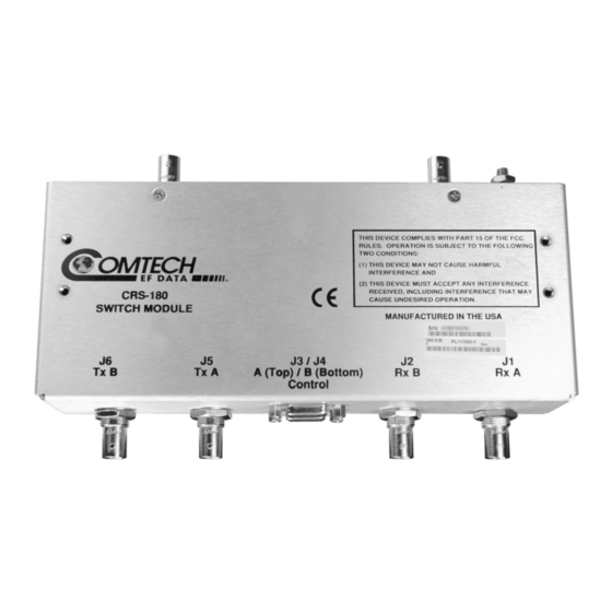
SUMMARY OF SPECIFICATIONS MN/CRS180.IOM CRS-180 IF 1:1 Redundancy Switch Revision 0 4.1.3 BNC C ODEM ONNECTORS There are four 50Ω BNC female connectors located on the modem side of the IF Switch Module. Refer to Table 4for details. Table 4. Modem Side BNC Connectors... -
Page 27: Figure 5. Antenna Side Connectors And Ground Lug
Revision 0 NTENNA ONNECTORS Two 50Ω female BNC connectors on the antenna side of the CRS-180 IF Switch Module provide the coaxial cable connections to the outdoor transmit and receive equipment (BUC and LNB). Refer to Figure 5. Type N Connector... - Page 28 SUMMARY OF SPECIFICATIONS MN/CRS180.IOM CRS-180 IF 1:1 Redundancy Switch Revision 0 Note: 4–16...
-
Page 29: Chapter 5. Summary Of Specifications
SUMMARY OF SPECIFICATIONS MN/CRS180.IOM CRS-180 IF 1:1 Redundancy Switch Revision 0 Chapter 5. SUMMARY OF SPECIFICATIONS Equipment Type IF 1:1 Redundancy Switch Manufacturer Comtech EF Data, Tempe, Arizona Modems Comtech EF Data CDM-570 Supported Operating Modes Fully Automatic under control of supporting 1:1 switch. - Page 30 SUMMARY OF SPECIFICATIONS MN/CRS180.IOM CRS-180 IF 1:1 Redundancy Switch Revision 0 Weight 1.1lbs (0.5kg) Dimensions 1.7 H x 5.7 W x 4.1 D inches (43 H x 143 W x 104 D mm [excluding connectors]) 19-inch rack mounting kit available.
- Page 31 METRIC CONVERSIONS Units of Length Unit Centimeter Inch Foot Yard Mile Meter Kilometer Millimeter 1 centimeter — 0.3937 0.03281 0.01094 6.214 x 10 0.01 — — 1 inch 2.540 — 0.08333 0.2778 1.578 x 10 0.254 — 25.4 1 foot 30.480 12.0 —...
- Page 32 2114 85281 WEST TH STREET TEMPE ARIZONA 480 • 333 • 2200 PHONE 480 • 333 • 2161...