
Related Manuals for Samson Trovis 6493


Summary of Contents for Samson Trovis 6493
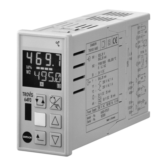
- Page 1 Automation System TROVIS 6400 Compact Controller TROVIS 6493 Mounting and Operating Instructions EB 6493-1 EN ® Firmware version 2.03 and 3.03 Electronics from SAMSON Edition February 2002...
- Page 2 Firmware versions 2.03 and 3.03 Modifications of firmware versions 2.03 and 3.03 The latest version of the TROVIS 6493 Compact Controller is equipped with an infrared inter- face. Apart from setting and operating the controller using the operator keys on the front panel, the integrated infrared interface allows you to configure, parameterize and operate the control- ler using the TROVIS-VIEW Configuration and Operator Interface.
-
Page 3: Table Of Contents
Contents Contents Notes ....... . . 5 Operation ....... 6 Display . - Page 4 Contents 3.5.5 BLOC Locking of output signal Y PID ....39 3.5.6 FUNC Function generation of output variable....39 3.5.7 Y.VA Output signal range .
-
Page 5: Notes
Notes Notes The TROVIS 6493 Compact Controller is a microprocessor-based controller with a flexible soft- ware design for the automation of industrial process plants. It is suitable for single control loops as well as for more complex control tasks. The flexible software design allows you to configure control circuits without changing the hardware. -
Page 6: Operation
Operation Operation The TROVIS 6493 Compact Controller can be operated either directly using the keys on the front panel or using the TROVIS-VIEW Configuration and Operator Interface (see section 2.7) for configuration, parameterization and operation. In the following, we will explain how to operate the controller with the keys on the front panel. -
Page 7: Keys
Operation 2.2 Keys The compact controller is operated using six keys whose function depends on the selected level. Function in operating level Function in setup level Enter key Provides access to setup level. Activates functions and parameters (yellow) to be changed (display blinks). Activates a new reference variable if Confirms new settings of functions its icon (W, W2 or WE) blinks in the... -
Page 8: Operating Level
Operation 2.3 Operating level In the operating level, Press Comments you can view different variables: Press selector key repeat- W2 and WE are only dis- W, W2, WE, Y, Xd edly until the desired vari- played when you have able appears on the dis- activated them in SETP play. -
Page 9: Setup Level
Operation 2.4 Setup level This level enables you to configure and parameterize the compact controller. You can enter the setup level from the operating level by pressing the enter key once. Here, you may adapt preset functions to your specific needs (configure) and change parameters. The functions are ar- ranged in nine main groups: (control parameters) (input functions) -
Page 10: Key Number
Operation 2.5 Key number You are prompted to enter the key number when you want to change the settings of functions and parameters. The compact controller can be operated with or without a key number. Factory default is without key number. Each time you wish to change a function or parameter in the setup level for the first time, you will be prompted to enter the key number. - Page 11 Operation Press Reading on display Comment You are in operating level. The reading on the display looks like this. KEY blinks. Note! If the reading on the display looks like this, the key number can always be changed. KEY blinks. Enter the service key number.
-
Page 12: Example For Configuration And Parameterization
Operation Press Reading on display Comment You have confirmed the new key number and returned to the selected function or parameter. In our example, we have re- turned to the Kp value. 2.6 Example for configuration and parameterization We will use the "Table of functions and parameters" provided in Appendix A for this example. The exercise consists of setting up the controller as a PID controller and adjusting the parameters accordingly. - Page 13 Operation Press Reading on display Comment Browse through the main groups (in the ta- repeatedly ble in Appendix A, you move from top to until CNTR bottom) until you get to the main group appears on the CNTR. Here, you can adjust the dynamic display.
- Page 14 Operation Press Reading on display Comment The display will look like this if you have en- tered the key number correctly. If not, you will be prompted again. The upper line blinks, meaning that you may change the settings of the function. In the table, you have moved one column further to the right and have reached "Setting options".
- Page 15 Operation Press Reading on display Comment KP blinks, i.e. you can change this parame- ter. Enter a new value for KP. In our example it is 1.5. The upper line continues to blink. You have confirmed the new value for KP. The upper line stops blinking.
-
Page 16: Trovis-View Configuration And Operator Interface
Operation 2.7 TROVIS-VIEW Configuration and Operator Interface The TROVIS 6493 Compact Controller can be configured, parameterized and operated using SAMSON's TROVIS-VIEW Configuration and Operator Interface via the infrared interface in- tegrated in the front panel. Operating TROVIS-VIEW is similar to working in Windows Explorer. Apart from configuration, parameterization and operation, TROVIS-VIEW provides additional features to record the compact controller. - Page 17 Operation TROVIS 6493 Infrared adapter Optional COM 1...COM 4 port of computer Fig. 1 · Connecting an infrared adapter EB 6493-1 EN...
-
Page 18: Functions Of The Compact Controller
Functions of the compact controller Functions of the compact controller In this section, all functions of the setup level are described. We assume that you are familiar with the operation of this controller and know how to change functions and parameters. The compact controller contains nine main groups: PAR, IN, SETP, CNTR, OUT, ALRM, AUX, TUNE and I-O. - Page 19 Functions of the compact controller Fig. 2 · Main group IN EB 6493-1 EN...
-
Page 20: In1 Input Signal Range In1
Functions of the compact controller 3.2.1 IN1 Input signal range IN1 This function enables you to define the input signal type and range for the analog input In1. The parameters' lower and upper range values must be given as absolute values. Choose between: 0-20 mA 0 to 20 mA input 4-20 mA 4 to 20 mA input... -
Page 21: Meas Measuring Range Monitoring For Analog Input 1 And 2
Functions of the compact controller Parameters to be set Lower range value as absolute value Upper range value as absolute value 3.2.3 MEAS Measuring range monitoring for analog input 1 and 2 This function enables you to define whether the measuring ranges of the analog inputs are to be monitored either for exceeding or falling below the measuring range. -
Page 22: Clas Assignment Of X And We
Functions of the compact controller Note! When values exceed or fall below the measuring range, Y1K1 only becomes effective when the compact controller is in automatic mode. The parameter Y1K1 can also be set in the main group OUT via the SAFE function as well as in the main group AUX via the RE.CO function (see sections 3.5.1 and 3.7.1). -
Page 23: Sqr Root Extraction
Functions of the compact controller Parameters to be set TS.X Time constant X filter in seconds TS.WE Time constant WE filter in seconds 3.2.7 SQR Root extraction This function enables you to root-extract the signals X as well as WE. Thus, you may easily cal- culate the flow rate from a differential pressure, for example. - Page 24 Functions of the compact controller Function generation means that a signal is re-evaluated to be further processed. This al- lows you to adapt auxiliary, reference or equivalent vari- K7.Y ables required for measuring K5.Y and control to your specific control loop. For this purpose, you must specify 7 points to characterize the relationship K1.Y...
-
Page 25: Setp Reference Variable
Functions of the compact controller Note! The course of the polygonal curve is not limited by the software. Polygonal curves with more than one maximum or minimum are possible. However, make sure that you assign only one ordinate value to one abscissa value. Otherwise, you risk to lose clear assignment of the in- put signal. - Page 26 Functions of the compact controller Fig. 4 · Main group SETP EB 6493-1 EN...
-
Page 27: Sp.va
Functions of the compact controller 3.3.1 SP.VA This function enables you to define which reference variables are active: W, W2 and/or WE. When you activate WE, follow-up control will automatically be effective, unless you use WE as input for the position transmission of a three-step output with external position feedback (F01 WE), or for feedforward control (F02 WE). -
Page 28: Sp.fu
Functions of the compact controller 3.3.2 SP.FU This function enables you to define a set point ramp and change between the different reference variables via the binary input. Set point ramp means that the reference variable changes at a constant rate. When the ref- WINT erence variable is changed, the compact controller follows... -
Page 29: Cntr Controller Structure And Functions
Functions of the compact controller You can use the binary input to change between the internal and external reference variable: Changeover of W via BI1 oFF CH.SP No changeover between internal reference variable W (W2) and external reference variable WE F01 CH.SP Changeover between active internal reference variable W (W2) and external reference variable WE via binary input BI1... - Page 30 Functions of the compact controller — — Fig. 6 · Main group CNTR EB 6493-1 EN...
-
Page 31: Sign Inversion Of Error Xd
Functions of the compact controller Parameters to be set Proportional-action coefficient Reset time Derivative-action time TVK1 Derivative-action gain Y.PRE Y rate action DZXD Dead band of error DZXD Limitation of error, lower limit DZXD Limitation of error, upper limit 3.4.2 SIGN Inversion of error Xd This function enables you to reverse the input operating direction. -
Page 32: Ch.ca Control Mode Changeover P(D)/Pi(D) Control
Functions of the compact controller 3.4.4 CH.CA Control mode changeover P(D)/PI(D) control Control mode changeover enables the compact controller to be operated under varying operat- ing conditions with different dynamic behaviors according W, XD to the control algorithm. Gen- erally, control mode change- P(D) CLI.P over is only useful when a con-... -
Page 33: M.adj Operating Point Adjustment In Manual Mode For Ypid
Functions of the compact controller 3.4.5 M.ADJ Operating point adjustment in manual mode for Y This function enables you to activate operating point adjustment in manual mode. In the factory defaults, this option is deactivated. To activate the operating point adjustment proceed as fol- lows: in manual mode, adjust the output variable using the cursor keys to the desired value. -
Page 34: Ac.va Increase, Decrease Of Actual Value
Functions of the compact controller WE' [%] WE’ = + (WE – FC.K1) FC.K2 + FC.K3 FC.K2 FC.K3 FC.K1 WE [%] WE' [%] WE’ = – (WE – FC.K1) FC.K2 + FC.K3 FC.K3 FC.K2 FC.K1 WE [%] -WE' [%] Fig. 9 · Feedforward control with positive (a) and negative (b) signs 3.4.8 AC.VA Increase, decrease of actual value This function enables you to increase or decrease the actual value. -
Page 35: Output Functions
Functions of the compact controller Note! Several functions can be assigned to the binary input! 3.5 Output functions This main group enables you to define the output functions of the compact controller. You may specify whether the compact controller operates with continuous-action or switching output. The output signal can be limited and ramps can be defined. - Page 36 Functions of the compact controller — — Fig. 9 · Main group OUT EB 6493-1 EN...
-
Page 37: Y.lim Output Signal Limitation Ypid
Functions of the compact controller 3.5.3 Y.LIM Output signal limitation Y Output signal limitation is always active. When entering parameter level, only the minimum and maximum output variable may be set. on LI.YP Output signal limitation Y activated Parameters to be set Y Minimum output variable Y Maximum output variable 3.5.4 RAMP Output ramp or limitation of rate of output changes Y... - Page 38 Functions of the compact controller The rate of output changes limited decreasing and an increasing output variable (F03 RA.YP), for an increasing output vari- able (F04 RA.YP), or for a de- creasing output variable (F05 RA.YP). In the limited direc- tion(s), the output variable changes only as fast as the pa- Input signal without limitation...
-
Page 39: Bloc Locking Of Output Signal Ypid
Functions of the compact controller 3.5.5 BLOC Locking of output signal Y This function locks the output signal upon activation of the binary input BI1. As a result, the cur- rent value of the output variable at the controller output remains unchanged as long as the bi- nary input is active. -
Page 40: Y.src Assignment Of Continuous-Action Output
Functions of the compact controller 3.5.8 Y.SRC Assignment of continuous-action output This function enables you to determine whether the continuous-action output is used as control- ler output (PID output) or assigned to the inputs X or WE, or to error. Optionally, the signals can then be transferred to a recorder. -
Page 41: C.out Configuration Of Two-Step Or Three-Step Output
Functions of the compact controller 3.5.10C.OUT Configuration of two-step or three-step output This function enables you to select a two-step or three-step output. The active two-step output is easily identified by the icon. For the three-step output, the icon indicates an active Y+ out- put, whereas the icon indicates an active Y–... - Page 42 Functions of the compact controller Two-step output The two-step output can only assume two states: on (1) or off (0). This controller output is used for applications, such as electric radiators with thermostat behavior. This version of the two-step output corresponds with a monitoring of the limit value violation by the Y The parameters dead band TZ and XSDY determine the switch-on and switch-off point of the two-step output.
- Page 43 Functions of the compact controller Three-step output with internal position feedback For the three-step output with internal position feedback, the position of a valve is determined by the transit time of the connected actuator. This transit time needs to be specified as parameter The output variable of the three-step output can assume three values: –100 %, 0 and 100 %.
- Page 44 Functions of the compact controller XSDY Y– Y– XSDY Fig. 13 · Three-step output with internal position feedback XSDY Y– Y– XSDY Fig. 14 · Three-step output with external position feedback EB 6493-1 EN...
- Page 45 Functions of the compact controller Parameters to be set XSDY Differential gap of two-step/three-step output in % Dead band of three-step output in % Two-step output with pulse-pause modulation (PPM) The two-step output with pulse-pause modulation (PPM) converts the continuous Y signal into a pulse sequence whose pulse-pause ratio varies depending on the Y value (see Fig.
- Page 46 Functions of the compact controller TYL1 = 50% KPL1 TYL1 TYL1 TYL1 Fig. 15 · Two-step output with PPM EB 6493-1 EN...
- Page 47 Functions of the compact controller Three-step output with internal position feedback and PPM The three-step output with internal position feedback and pulse-pause modulation converts the three-step signal into a pulse sequence. The characteristic of this output is illustrated in Fig. 16. The position of the control valve is deter- mined by the transit time of the connected actuator.
- Page 48 Functions of the compact controller TYL2, TYL1 TYL1 TYL1 KPL2 KPL1 TYL2 TYL2 Fig. 16 · Three-step output with internal position feedback and PPM EB 6493-1 EN...
- Page 49 Functions of the compact controller Three-step output with external position feedback and PPM This type of three-step output is similar to the three-step output with internal position feedback and pulse-pause modulation (PPM). The only difference is that the position of a connected actu- ator is fed back externally via the WE input, for example using a potentiometer.
-
Page 50: B.out Configuration Of Binary Outputs Bo1 And Bo2
Functions of the compact controller 3.5.11B.OUT Configuration of binary outputs BO1 and BO2 This function enables you to specify which operating conditions are to be indicated by the bi- nary outputs BO1 and BO2. You can view the states of the binary outputs in the I-O level with the BIN function (see section 3.9.4). -
Page 51: Alrm Alarm Functions
Functions of the compact controller 3.6 ALRM Alarm functions This main group enables you to determine the functions of the limit relays L1 and L2. The limit relays monitor variables as to whether they exceed or fall below a limit value. The limit relay can assume two switching states. -
Page 52: Lim1 Limit Relay L1
Functions of the compact controller 3.6.1 LIM1 Limit relay L1 The function of the limit relays has been described in the previous section 3.6. Note! Functions of the two-step or three-step output C.OUT (see section 3.5.10) and functions of the binary outputs B.OUT (see section 3.5.11) have priority over the settings of the functions LIM1 and LIM2. -
Page 53: Aux Additional Functions
Functions of the compact controller Choose between: Limit relay L2 oFF L2 Limit relay L2 deactivated Lo L2.X L2 activated when X is not reached Hi L2.X L2 activated when X is exceeded Lo L2.WE L2 activated when WE is not reached Hi L2.WE L2 activated when WE is exceeded Lo L2.YP... -
Page 54: St.in Resetting To Factory Defaults
Functions of the compact controller 3.7.2 ST.IN Resetting to factory defaults This function enables you to reset all settings for parameters, functions and calibrating values together or individually: FrEE INIT Resetting deactivated/completed All INIT Resetting all the functions, parameters and the key number FUnC INIT Resetting all the functions PArA INIT... -
Page 55: Freq Power Frequency
Functions of the compact controller 3.7.5 FREQ Power frequency This function enables you to set the power frequency of the system to either 50 or 60 Hz. Choose between: on 50Hz Power frequency set to 50 Hz on 60Hz Power frequency set to 60 Hz 3.7.6 DP Decimal place setting This function enables you to determine the number of decimal places for all variables directly re- lated to the analog inputs In1 and In2. - Page 56 Functions of the compact controller When start-up adaption has been successfully completed, the determined parameters become effective immediately. The compact controller is in manual mode. Now switch to automatic mode. Choose between: oFF ADP.S No adaption run ADP.S Launch start-up adaption Parameter to be set Y.JMP Value of step response in %...
- Page 57 Functions of the compact controller Press Display shows Comments You are leaving the parameter level. ADP.S (blinks) ADP.S (blinks) ADP.S Adaption is started. In sequence, status (blinks) ADP.S messages indicating the progress of the adaption are displayed in the upper sec- tion.
-
Page 58: I-O View Process Data
Functions of the compact controller Interferences too strong Increase Y.JMP and check interferences. Selected PID setting does Set P, PI or PID control in the C.PID function not allow adaption (main group CNTR). Control signal in limit Modify Y.JMP. Disturbance Restart adaption. -
Page 59: Bin Status Of Binary Input And Outputs
Functions of the compact controller 3.9.4 BIN Status of binary input and outputs This menu indicates the respective status of the binary input and outputs. Status of binary input BI1 on/oFF Status of binary output BO1 on/oFF Status of binary output BO2 on/oFF 3.9.5 ADJ Adjusting the analog inputs and output This function enables you to adjust zero and span for the analog inputs and the analog output. - Page 60 Practical examples Practical examples In this section, we will show you how to configure your TROVIS 6493 Compact Controller to im- plement fixed set point control, follow-up control and follow-up control with function genera- tion. We assume you know how to operate the controller. If not, read section 2. Note that there are two controller versions due to the different inputs In2! 4.1 Fixed set point control...
-
Page 61: Practical Examples
The control valve with positioner is controlled by a continuous output variable Y ranging from 4 to 20 mA. The controller version TROVIS 6493-02 with two mA inputs is used in this example. Proceed as follows: The controlled variable X represents the pressure p , which is measured via a two-wire transmitter and connected to the input In2. -
Page 62: Follow-Up Control
Practical examples By default, the output variable Y is set up for a continuous signal ranging from 4 to 20 mA. As a result, the output variable does not need to be modified in this example. The following table lists the required settings in short, together with the parameter definitions: Setup level Main group Function Setting... - Page 63 Practical examples 4.3 Follow-up control with function generation We will show you how to use function generation exempli- fying an outdoor tempera- ture-sensitive flow tempera- ture control loop, as illustrated in Fig. 21. The controlled variable repre- sents the flow temperature. The outdoor temperature is measured by a Pt 100 sensor and converted into a flow tem-...
-
Page 64: Follow-Up Control With Function Generation
Practical examples The following table lists the required settings: Setup level Main group Function Setting Parameter Value Comment -CO- -PA- -CO- 4-20 mA 0.0 [°C] Define measuring (default) 150.0 [°C] range for input 1 (tv) -CO- Assign controlled vari- CLAS able X (tv) to input In1 Assign external refer- ence variable WE (tA) - Page 65 Practical examples Setup level Main group Function Setting Parameter Value Comment -CO- -PA- -CO- 3.STP i.FB XSDY 0.8 [%] Define three-step C.OUT 2.0 [%] output with internal 90.0 [s] position feedback and appropriate parame- ters. Operating level Press selector key to view WE. Define WE as active Press enter key.
-
Page 66: P Controller
Start-up Start-up When all the inputs and outputs as well as the power supply are connected, the compact con- troller must be adapted to the desired control task. This means that you have to configure and parameterize the controller. Appendix C contains a checklist to fill in the adjusted settings if you wish. -
Page 67: Start-Up
Start-up Increase the KP value until the controlled system tends to oscillate. Slightly decrease the KP value until the oscillations are eliminated. Decrease the TN value until the controlled system tends to oscillate. Slightly increase the TN value until the oscillations are eliminated. 5.3 PD controller Enter KP = 0.1, TV = 1 and derivative-action gain TVK1 = 1. - Page 68 EB 6493-1 EN...
- Page 69 Installation Installation The TROVIS 6493 Compact Controller is a panel-mounting unit with front dimensions of 48 mm x 96 mm. To mount the controller, proceed as follows: 1. Make a control panel cut-out with dimensions of 45 +0.6 x 92 +0.8...
-
Page 70: Installation
Installation Depth with terminals: 158 (6.18) Compact controller Mounting bracket Control panel +0.6 +0.8 +0.023 +0.0315 Panel cut-out: 45 x 92 mm (1.77 x 3.622 inch) Fig. 22 · Installation with dimensions in mm (inch) EB 6493-1 EN... - Page 71 Electrical connections Electrical connections The compact controller has screw terminals suitable for lines up to 1.5 mm². For electrical installation, you are required to observe the VDE 0100 regulation and the regula- tions applicable in the country of usage. To avoid measurement errors or other faults, use screened cables for the signal lines of the ana- log and binary inputs running outside the switching cabinets.
-
Page 72: Electrical Connections
Electrical connections Voltage output for Binary input BI1 transmitter supply Binary output BI1 14 15 14 15 81 82 81 82 – Terminal example with internal supply – – 24 V 20 V, max. 25 mA Terminal example Note! The transmitter supply can only be with external supply used for one two-wire transmitter (at IN1 or at IN2) or for the supply of the binary input... - Page 73 Technical data Technical data Two analog inputs, optionally for controlled vari- Inputs able X or reference variable W 0(4) to 20 mA or 0(2) to 10 V or two-wire transmit- ter (see below) Analog input 1 Version 6493-01: temperature sensor or potentio- Analog input 2 (two controller versions) meter (see below) Version 6493-02: 0(4) to 20 mA or two-wire trans-...
-
Page 74: Technical Data
C = 2.2 nF and varistor U = 275 V Isolated transistor output, max. 50 V DC and 30 Binary output mA, min. 3 V DC Infrared interface Transfer protocol SAMSON protocol (SSP) Transfer rate 9600 bit/s Angle of reflection 50° Distance Max. - Page 75 Technical data EB 6493-1 EN...
- Page 76 Appendix A Appendix A Appendix A Table of functions and parameters Main Function Displayed Setting Description of function Details Parameters Parameter Parameter designation Range of values Factory group -CO- settings options -PA- selection [unit] default Control parameter (Press enter key only once to get to Kp). p.
- Page 77 Appendix A Appendix A Main Function Displayed Setting Description of function Details Parameters Parameter Parameter designation Range of values Factory group -CO- settings options -PA- selection [unit] default -CO- on X on X Filtering of input variable X on -PA- DI.FI/X TS.X Time constant of X filter 0.1…...
- Page 78 Appendix A Appendix A Main Function Displayed Setting Description of function Details Parameters Parameter Parameter designation Range of values Factory group -CO- settings options -PA- selection [unit] default oFF WE oFF WE Function generation of WE off p. 23 -PA- FUNC/WE Output signal lower range value -999…...
- Page 79 Appendix A Appendix A Main Function Displayed KEY Setting Description of function Details Parameters Parameter Parameter designation Range of values Factory group -CO- settings options -PA- selection [unit] default Reference variable SETP -CO- on W Internal reference variable W (always active) -PA- SP.VA/W Internal reference variable 1 WRAN…...
- Page 80 Appendix A Appendix A Main Function Displayed KEY Setting Description of function Details Parameters Parameter Parameter designation Range of values Factory group -CO- settings options -PA- selection [unit] default Control structure and functions -CO- PI CP.YP PI CP.YP Dynamic behavior of controller output PI p.
- Page 81 Appendix A Appendix A Main Function Displayed KEY Setting Description of function Details Parameters Parameter Parameter designation Range of values Factory group -CO- settings options -PA- selection [unit] default Output functions -CO- oFF SA.VA oFF SA.VA Initialization of constant output value Y1K1 for Y p.
- Page 82 Appendix A Appendix A Main Function Displayed KEY Setting Description of function Details Parameters Parameter Parameter designation Range of values Factory group -CO- settings options -PA- selection [unit] default -CO- on Y.PID Assignment of continuous-action output p. 40 no PA Y.SRC/Y.PID No parameters Y.SRC on Y.PID...
- Page 83 Appendix A Appendix A Main Function Displayed KEY Setting Description of function Details Parameters Parameter Parameter designation Range of values Factory group -CO- settings options -PA- selection [unit] default Alarm functions ALRM -CO- oFF L1 oFF L1 Limit relay L1 deactivated p.52 LIM1 Lo L1.X...
- Page 84 Appendix A Appendix A Main Function Displayed KEY Setting Description of function Details Parameters Parameter Parameter designation Range of values Factory group -CO- settings options -PA- selection [unit] default Additional functions -CO- F01 MODE Restart conditions after power failure p. 53 -PA- RE.CO/MODE Y1K1 Constant output value...
- Page 85 Appendix A Appendix A Main Function Displayed KEY Setting Description of function Details Parameters Parameter Parameter designation Range of values Factory group -CO- settings options -PA- selection [unit] default Start-up adaption TUNE -CO- oFF ADP.S oFF ADP.S Adaption off p. 55 -PA- ADAP/ADP.S Proportional-action coefficient 0.1…100.0 [1]...
- Page 86 Appendix B Error messages Display blinks Reason Remedy No access to EEPROM Return device to SAMSON EEPROM cannot be programmed Return device to SAMSON Default settings lost Return device to SAMSON Functions changed without user Check settings of the functions...
- Page 87 Appendix C Appendix C Checklist TROVIS 6493 Compact Controller Controller no.: Firmware no.: Date of configuration: Signature: Main Function Settings Parameters group -CO- Y.PRE MEAS Y1K1 CLAS DI.FI TS.X TS.WE EB 6493-1 EN...
- Page 88 Appendix C Main Function Settings Parameters group -CO- FUNC (cont.) K .X K. Y K .X K. Y SETP SP.VA WINT WINT WRAN WRAN SP.FU RAMP TSRW WIRA CH.SP CNTR C.PID TVK1 Y.PRE DZXD DZXD DZXD SIGN D.PID CH.CA CLI.P CLI.M EB 6493-1 EN...
- Page 89 Appendix C Main Function Settings Parameters group -CO- CNTR M.ADJ (cont.) DIRE F.FOR FC.K1 FC.K2 FC.K3 AC.VA AV.K1 SAFE Y1K1 MA.AU Y.LIM RAMP TSRA Y1RA BLOC FUNC K .X K. Y Y.VA Y.SRC CALC CA.K1 CA.K2 CA.K3 C.OUT KPL1 KPL2 TYL1 TYL2 MinTYL1...
- Page 90 Main Function Settings Parameters group -CO- B.OUT (cont.) ALRM LIM1 LI.X LI.WE LI.YP LI.XD L.HYS LIM2 LI.X LI.WE LI.YP LI.XD L.HYS RE.CO Y1K1 KEYL VIEW FREQ EB 6493-1 EN...
- Page 91 EB 6493-1 EN...
-
Page 92: Index
Index Index Continuous-action output assignment....40 mathematical adaption ... 40 Control mode changeover... . 32 Actual value Control modes . - Page 93 Index Function generation input variables ....23 Ni 100 ......20 output variable .
- Page 94 Index Reference variable ramp... . . 28 Reset time TN ..... 31 Technical data .
- Page 97 Controlled variable X Bar graph Xd in % Value of W, W2, WE, Y or Xd Enter key Limit relay L2 active Selector key Three-point output – Manual/automatic key Limit relay L1 active Cursor key (increase, next) Three-point output + Cursor key (decrease, back) Fault alarm Return key...
- Page 98 SAMSON AG · MESS- UND REGELTECHNIK Weismüllerstraße 3 · 60314 Frankfurt am Main · Germany Phone: +49 69 4009-0 · Fax: +49 69 4009-1507 EB 6493-1 EN Internet: http://www.samson.de...