Cisco 7010 Installation Manual
Firepower 7000 series; firepower 8000 series
Hide thumbs
Also See for 7010:
- Product user manual (151 pages) ,
- Help manual (132 pages) ,
- Replacement instructions manual (23 pages)
Table of Contents
Advertisement
Advertisement
Chapters
Table of Contents

Related Manuals for Cisco 7010


Summary of Contents for Cisco 7010
- Page 1 Firepower 7000 and 8000 Series Installation Guide Version 6.0 November 5, 2015 Cisco Systems, Inc. www.cisco.com Cisco has more than 200 offices worldwide. Addresses, phone numbers, and fax numbers are listed on the Cisco website at www.cisco.com/go/offices.
- Page 2 OR ITS SUPPLIERS HAVE BEEN ADVISED OF THE POSSIBILITY OF SUCH DAMAGES. Cisco and the Cisco logo are trademarks or registered trademarks of Cisco and/or its affiliates in the U.S. and other countries. To view a list of Cisco trademarks, go to this URL: www.cisco.com/go/trademarks.
-
Page 3: Table Of Contents
Introduction to the Firepower System Firepower System Appliances 7000 and 8000 Series Appliances Virtual Appliances Cisco ASA with FirePOWER Services Appliances Delivered with Version 6.0 Supported Capabilities by Firepower Management Center Model Supported Capabilities by Managed Device Model 7000 and 8000 Series Device Chassis Designations... - Page 4 Contents Routed Interfaces Hybrid Interfaces Connecting Devices to Your Network Using a Hub Using a Span Port Using a Network Tap Cabling Inline Deployments on Copper Interfaces Special Case: Connecting Firepower 8000 Series Devices Deployment Options Deploying with a Virtual Switch Deploying with a Virtual Router Deploying with Hybrid Interfaces Deploying a Gateway VPN...
- Page 5 System Status Mode Information Mode Error Alert Mode Hardware Specifications Rack and Cabinet Mounting Options Firepower 7000 Series Devices Firepower 7010, 7020, 7030, and 7050 Firepower 7110 and 7120 Firepower 7115, 7125, and AMP7150 7-13 Firepower 8000 Series Devices 7-21...
- Page 6 Contents Obtaining the Restore ISO and Update Files Beginning the Restore Process Starting the Restore Utility Using KVM or Physical Serial Port Starting the Restore Utility Using Lights-Out Management Using the Interactive Menu to Restore an Appliance Identifying the Appliance’s Management Interface Specifying ISO Image Location and Transport Method Updating System Software and Intrusion Rules During Restore 8-10...
- Page 7 Contents Using SFP Transceivers in 3D71x5 and AMP7150 Devices 3D71x5 and AMP7150 SFP Sockets and Transceivers Inserting an SFP Transceiver To insert an SFP transceiver: Removing an SFP Transceiver Inserting and Removing Firepower 8000 Series Modules Module Slots on the Firepower 8000 Series Devices Firepower 81xx Family Firepower 82xx Family and 83xx Family Included Items...
- Page 8 Contents Firepower 7000 and 8000 Series Installation Guide...
-
Page 9: Introduction To The Firepower System
C H A P T E R Introduction to the Firepower System The Cisco Firepower System combines the security of an industry-leading network intrusion protection system with the power to control access to your network based on detected applications, users, and URLs. -
Page 10: Firepower System Appliances
Appliance Types The Firepower System can run on fault-tolerant, purpose-built physical network appliances available from Cisco. There are several models of each Firepower Management Center and managed device; these models are further grouped into series and family. Firepower 7000 and 8000 Series Installation Guide... -
Page 11: 7000 And 8000 Series Appliances
ESXi hosts using the VMware vSphere Hypervisor or vCloud Director environment. Either type of Management Center (physical or virtual) can manage any type of device: physical, virtual, and Cisco ASA with FirePOWER Services. Note, however, that many Firepower System capabilities are appliance dependent. -
Page 12: Appliances Delivered With Version 6.0
ASA FirePOWER interface names. Appliances Delivered with Version 6.0 The following table lists the appliances that Cisco delivers with Version 6.0 of the Firepower System. Table 1-1 Version 6.0 Firepower System Appliances... -
Page 13: Supported Capabilities By Firepower Management Center Model
Chapter 1 Introduction to the Firepower System Firepower System Appliances Table 1-1 Version 6.0 Firepower System Appliances (continued) Models/Family Firepower Series Form Type 83xx Family: 8000 Series hardware device 8350 • 8360, 8370, 8390 • AMP8350 • AMP8360, AMP8370, AMP8390 •... - Page 14 Chapter 1 Introduction to the Firepower System Firepower System Appliances Table 1-2 Supported Capabilities by Firepower Management Center Model Management Center Feature or Capability Management Center Virtual collect discovery data (host, application, and user) reported by managed devices and build a network map for your organization view geolocation data for your network traffic manage an intrusion detection and prevention (IPS) deployment manage devices performing Security Intelligence filtering...
-
Page 15: Supported Capabilities By Managed Device Model
Chapter 1 Introduction to the Firepower System Firepower System Appliances Supported Capabilities by Managed Device Model Devices are the appliances that handle network traffic; therefore, many Firepower System capabilities are dependent on the model of your managed devices. The following table matches the major capabilities of the system with the devices that support those capabilities, assuming you have the correct licenses installed and applied from the managing Firepower Management Center. -
Page 16: 7000 And 8000 Series Device Chassis Designations
The following table lists the chassis designations for the 7000 Series models available world-wide. Table 1-4 7000 Series Chassis Models Firepower and AMP Device Model Hardware Chassis Code 7010, 7020, 7030 CHRY-1U-AC 7050 NEME-1U-AC 7110, 7120 (Copper) GERY-1U-8-C-AC 7110, 7120 (Fiber) -
Page 17: Firepower System Components
Chapter 1 Introduction to the Firepower System Firepower System Components Table 1-5 8000 Series Chassis Models (continued) Firepower and AMP Device Model Hardware Chassis Code 8350, 8360, 8370, 8390 PG35-2U-AC/DC (AC or DC power) AMP830, AMP8360, AMP8370, AMP8390 PG35-2U-AC/DC (AC or DC power) Firepower System Components The sections that follow describe some of the key capabilities of the Firepower System that contribute to your organization’s security, acceptable use policy, and traffic management strategy. - Page 18 VPN tunnels from virtual routers on managed devices to remote devices or other third-party VPN endpoints Discovery and Identity Cisco’s discovery and identity technology collects information about hosts, operating systems, applications, users, files, networks, geolocation information, and vulnerabilities, in order to provide you with a complete view of your network.
-
Page 19: Licensing The Firepower System
(for some models) a malware storage pack. Regardless of whether you store a detected file, you can submit it to the Cisco cloud for a simple known-disposition lookup using the files SHA-256 hash value. You can also submit files for dynamic analysis, which produces a threat score. - Page 20 A Malware license requires a Protection license. A VPN license allows you to build secure VPN tunnels among the virtual routers on Cisco managed devices, or from managed devices to remote devices or other third-party VPN endpoints. A VPN license requires Protection and Control licenses.
-
Page 21: Security, Internet Access, And Communication Ports
Internet resources they need to operate correctly. With the exception of Cisco ASA with FirePOWER Services, Firepower System appliances support the use of a proxy server. For more information, see the Firepower Management Center Configuration Guide. -
Page 22: Communication Ports Requirements
Management Center RSS feed dashboard widget download RSS feed data from an external Any except virtual devices and source, including Cisco. ASA FirePOWER Security Intelligence filtering download Security Intelligence feed data from Management Center an external source, including the Firepower System Intelligence Feed. - Page 23 You can change the management port (8305/tcp); see the Firepower Management Center Configuration Guide. However, Cisco strongly recommends that you keep the default setting. If you change the management port, you must change it for all appliances in your deployment that need to communicate with each other.
-
Page 24: Preconfiguring Appliances
• submitted files 7000 and 8000 Series download software updates using the device’s devices local web interface. 7000 and 8000 Series, submit files to the Cisco cloud for dynamic virtual devices, and analysis. ASA FirePOWER 514/udp syslog Outbound send alerts to a remote syslog server. -
Page 25: Deploying On A Management Network
C H A P T E R Deploying on a Management Network The Firepower System can be deployed to accommodate the needs of each unique network architecture. The Management Center provides a centralized management console and database repository for the Firepower System. -
Page 26: Understanding Management Interfaces
Chapter 2 Deploying on a Management Network Understanding Management Interfaces Understanding Management Interfaces Management interfaces provide the means of communication between the Management Center and all devices it manages. Maintaining good traffic control between the appliances is essential to the success of your deployment. -
Page 27: Deployment Options
• eth0 eth1 on) interfaces require unique static IP addresses and hostnames. Cisco recommends that you do not set up DNS entries for additional management interfaces but instead register Management Centers and devices by IP addresses only for these interfaces. -
Page 28: Deploying With Network Routes
Chapter 2 Deploying on a Management Network Deploying with Network Routes The following graphic shows the management traffic channel and the event traffic channel over two management interfaces. You can use a dedicated management interface to carry only event traffic from multiple devices. In this configuration, each device is registered to a different management interface to carry the management traffic channel, and one management interface on the Management Center carries all event traffic channels from all devices. -
Page 29: Security Considerations
You can add more management interfaces to configure separate management and event traffic channel interfaces for each device. Security Considerations To deploy your management interfaces in a secure environment, Cisco recommends that you consider the following: Always connect the management interface to a trusted internal management network that is •... - Page 30 Chapter 2 Deploying on a Management Network Special Case: Connecting 8000 Series Devices Firepower 7000 and 8000 Series Installation Guide...
-
Page 31: Deploying Firepower Managed Devices
Note devices. For additional information about deployments, consult the Best Practices Guide, available from the Cisco sales department. Sensing Deployment Considerations Your sensing deployment decisions will be based on a variety of factors. Answering these questions can help you understand the vulnerable areas of your network and clarify your intrusion detection and prevention needs: •... -
Page 32: Understanding Sensing Interfaces
Chapter 3 Deploying Firepower Managed Devices Understanding Sensing Interfaces Understanding Sensing Interfaces The sections that follow describe how different sensing interfaces affect the capabilities of the Firepower System. In addition to passive and inline interfaces, you can also have routed, switched, and hybrid interfaces. -
Page 33: Switched Interfaces
Chapter 3 Deploying Firepower Managed Devices Understanding Sensing Interfaces All Firepower devices can contain configurable bypass interfaces. 8000 Series devices can also contain NetMods with interfaces that cannot be configured for bypass. For more information on NetMods, see Firepower 8000 Series Modules, page 7-32. -
Page 34: Hybrid Interfaces
Chapter 3 Deploying Firepower Managed Devices Connecting Devices to Your Network Physical routed interfaces are physical interfaces with routing configured. Uses physical routed • interfaces to handle untagged VLAN traffic. • Logical switched interfaces are an association between a physical interface and a VLAN tag. Use logical interfaces to handle traffic with designated VLAN tags. -
Page 35: Using A Span Port
Chapter 3 Deploying Firepower Managed Devices Connecting Devices to Your Network Some devices are marketed as hubs but actually function as switches and do not broadcast each packet to every port. If you attach your managed device to a hub, but do not see all the traffic, you may need to purchase a different hub or use a switch with a Span port. -
Page 36: Special Case: Connecting Firepower 8000 Series Devices
Chapter 3 Deploying Firepower Managed Devices Connecting Devices to Your Network Figure 3-1 Crossover Bypass Connection Cabling The following table indicates where you should use crossover or straight-through cables in your hardware bypass configurations. Note that a Layer 2 port functions as a straight-through (MDI) endpoint in the deployment, and a Layer 3 port functions as a crossover (MDIX) endpoint in the deployment. -
Page 37: Deployment Options
Chapter 3 Deploying Firepower Managed Devices Deployment Options Deployment Options When you place your managed device on a network segment, you can monitor traffic using an intrusion detection system or protect your network from threats using an intrusion prevention system. You can also deploy your managed device to function as a virtual switch, virtual router, or gateway VPN. -
Page 38: Deploying With A Virtual Router
Chapter 3 Deploying Firepower Managed Devices Deployment Options Figure 3-2 Virtual Switches on a Managed Device In this example, the managed device monitors traffic from two separate networks, 172.16.1.0/20 and 192.168.1.0/24. Although both networks are monitored by the same managed device, the virtual switch passes traffic only to those computers or servers on the same network. -
Page 39: Deploying With Hybrid Interfaces
Chapter 3 Deploying Firepower Managed Devices Deployment Options When you deploy a virtual router on your managed device, you can use one appliance to connect multiple networks to each other, and to the Internet. Figure 3-3 Virtual Routers on a Managed Device In this example, the managed device contains a virtual router to allow traffic to travel between the computers on network 172.16.1.0/20 and the servers on network 192.168.1.0/24 (indicated by the blue and green lines). -
Page 40: Deploying A Gateway Vpn
The secure tunnel between the gateways protects communication between them. You configure the Firepower System to build secure VPN tunnels from the virtual routers of Cisco managed devices to remote devices or other third-party VPN endpoints using the Internet Protocol Security (IPSec) protocol suite. -
Page 41: Deploying With Policy-Based Nat
Chapter 3 Deploying Firepower Managed Devices Deployment Options Mesh deployments connect all endpoints together by means of VPN tunnels. This offers redundancy • in that when one endpoint fails, the remaining endpoints can still communicate with each other. Use a mesh deployment to connect a group of decentralized branch office locations to ensure that traffic can travel even if one or more VPN tunnels fails. - Page 42 Chapter 3 Deploying Firepower Managed Devices Deployment Options allow all traffic to enter your network, and inspect the traffic with a network discovery policy only • allow all traffic to enter your network, and inspect the traffic with intrusion and network discovery •...
- Page 43 Chapter 3 Deploying Firepower Managed Devices Deployment Options An incoming packet is first checked against any fast-path rules. If there is a match, the traffic is fast-pathed. If there is no match, Security Intelligence-based filtering determines if the packet is blacklisted.
- Page 44 Chapter 3 Deploying Firepower Managed Devices Deployment Options On the Internal Network A malicious attack can originate from a computer on your internal network. This can be a deliberate act (for example, an unknown computer appears unexpectedly on your network), or an accidental infection (for example, a work laptop infected off-site is connected to the network and spreads a virus).
- Page 45 Chapter 3 Deploying Firepower Managed Devices Deployment Options On a Remote or Mobile Network Remote networks, located off-site, often use a virtual private network (VPN) to provide access to the primary network. Mobile devices and the use of personal devices for business purposes (for example, using a “smart phone”...
-
Page 46: Using Multiple Sensing Interfaces On A Managed Device
Chapter 3 Deploying Firepower Managed Devices Using Multiple Sensing Interfaces on a Managed Device Using Multiple Sensing Interfaces on a Managed Device The managed device offers multiple sensing interfaces on its network modules. You can use multiple sensing interfaces on managed devices to: recombine the separate connections from a network tap •... - Page 47 Chapter 3 Deploying Firepower Managed Devices Using Multiple Sensing Interfaces on a Managed Device You can use the virtual switch to replace both the tap and the switch in your deployment. Note that if you replace the tap with a virtual switch, you lose the tap packet delivery guarantee. You can also create interfaces to capture data from separate networks.
-
Page 48: Complex Network Deployments
Chapter 3 Deploying Firepower Managed Devices Complex Network Deployments Complex Network Deployments Your enterprise’s network may require remote access, such as using a VPN, or have multiple entry points, such as a business partner or banking connection. Integrating with VPNs Virtual private networks, or VPNs, use IP tunneling techniques to provide the security of a local network to remote users over the Internet. -
Page 49: Detecting Intrusions On Other Points Of Entry
Chapter 3 Deploying Firepower Managed Devices Complex Network Deployments Detecting Intrusions on Other Points of Entry Many networks include more than one access point. Instead of a single border router that connects to the Internet, some enterprises use a combination of the Internet, modem banks, and direct links to business partner networks. -
Page 50: Deploying In Multi-Site Environments
Chapter 3 Deploying Firepower Managed Devices Complex Network Deployments Deploying in Multi-Site Environments Many organizations want to extend intrusion detection across a geographically disparate enterprise and then analyze all the data from one location. The Firepower System supports this by offering the Firepower Management Center, which aggregates and correlates events from managed devices deployed throughout the organization’s many locations. - Page 51 Chapter 3 Deploying Firepower Managed Devices Complex Network Deployments You can replace the firewalls and routers with the managed device deployed in each network segment. Firepower 7000 and 8000 Series Installation Guide 3-21...
-
Page 52: Integrating Multiple Management Interfaces Within A Complex Network
Chapter 3 Deploying Firepower Managed Devices Complex Network Deployments Integrating Multiple Management Interfaces within a Complex Network You can configure multiple management interfaces in any deployment to isolate traffic from devices that monitor different networks and are managed by the same Firepower Management Center. Multiple management interfaces allow you to add a management interface with a unique IP address (IPv4 or IPv6) to your Firepower Management Center, and create a route from that management interface to a network that contains the device you want to manage. -
Page 53: Integrating Managed Devices Within Complex Networks
NAT device. In this case, Cisco recommends that you position managed devices inside the network segment protected by the proxy or NAT device to ensure that hosts are correctly detected. - Page 54 Chapter 3 Deploying Firepower Managed Devices Complex Network Deployments Firepower 7000 and 8000 Series Installation Guide 3-24...
- Page 55 C H A P T E R Prepare to Installation This chapter prepares you to install the Cisco Firepower 7000 and 8000 Series appliances and contains the following sections: Installation Guidelines, page 7-1 Safety Recommendations, page 7-2 Maintain Safety with Electricity, page 7-3...
-
Page 56: Safety Recommendations
Chapter 7 Prepare to Installation Safety Recommendations Safety Recommendations Use the information in the following sections to help ensure your safety and to protect the chassis. This information may not address all potentially hazardous situations in your working environment, so be alert and exercise good judgment at all times. -
Page 57: Maintain Safety With Electricity
Chapter 7 Prepare to Installation Maintain Safety with Electricity Do not cover or block vents, or otherwise enclose the appliance. • Maintain Safety with Electricity Before working on a chassis, be sure the power cord is unplugged. Be sure to read the Regulatory and Warning Compliance Safety Information... -
Page 58: Site Environment
Chapter 7 Prepare to Installation Site Environment Site Environment When planning the site layout and equipment locations, consider the information in the next section to help avoid equipment failures and reduce the possibility of environmentally caused shutdowns. If you are currently experiencing shutdowns or unusually high error rates with your existing equipment, these considerations may help you isolate the cause of failures and prevent future problems. -
Page 59: Installing A Firepower Managed Device
(required tray and rack-mounting kit available separately for the Firepower • 7010, 7020, 7030, and 7050) Security Considerations Before you install your appliance, Cisco recommends that you consider the following: Locate your appliance in a lockable rack within a secure location that prevents access by • unauthorized personnel. -
Page 60: Identifying The Management Interfaces
Refer to the correct illustration for your appliance as you follow the installation procedure. Firepower 7000 Series The Firepower 7010, 7020, 7030, and 7050 are 1U appliances that are one-half the width of the chassis tray. The following illustration of the front of the chassis indicates the default management interface. -
Page 61: Identifying The Sensing Interfaces
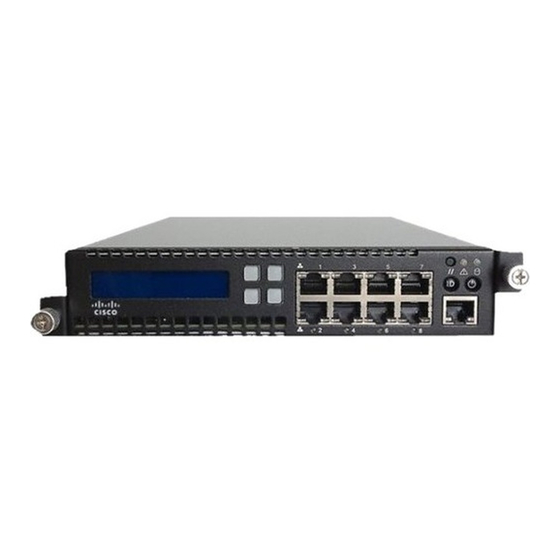
Chapter 4 Installing a Firepower Managed Device Identifying the Sensing Interfaces The Firepower 8250 is available as a 2U appliance. The Firepower 8260, 8270, and 8290 are available as 2U appliances with one, two, or three secondary 2U appliances. The following illustration of the rear of the chassis indicates the location of the default management interface for each 2U appliance. - Page 62 Identifying the Sensing Interfaces Firepower 7010, 7020, 7030, and 7050 The Firepower 7010, 7020, 7030, and 7050 are delivered with eight copper port sensing interfaces, each with configurable bypass capability. The following illustration of the front of the chassis indicates the location of the sensing interfaces.
- Page 63 Chapter 4 Installing a Firepower Managed Device Identifying the Sensing Interfaces Figure 4-3 Eight-Port 1000BASE-T Copper Interfaces You can use these connections to passively monitor up to eight separate network segments. You can also use paired interfaces in inline or inline with bypass mode to deploy the device as an intrusion prevention system on up to four networks.
- Page 64 Cisco SFP transceivers are available in 1G copper, 1G short range fiber, or 1G long range fiber, and are hot-swappable. You can use any combination of copper or fiber transceivers in your device in either passive or inline configuration.
-
Page 65: Firepower 8000 Series
Chapter 4 Installing a Firepower Managed Device Identifying the Sensing Interfaces Figure 4-8 Sample SFP Transceivers Figure 4-9 SFP Sockets Firepower 8000 Series The 8000 Series is available as a 1U device with a 10G network switch or a 2U device with either a 10G or a 40G network switch. - Page 66 Chapter 4 Installing a Firepower Managed Device Identifying the Sensing Interfaces Modules are not hot-swappable. See Inserting and Removing Firepower 8000 Series Modules, page C-1 Caution for more information. The following illustrations of the front of the chassis indicates the location of the module slots that contain the sensing interfaces.
- Page 67 Chapter 4 Installing a Firepower Managed Device Identifying the Sensing Interfaces a quad-port 1000BASE-SX fiber interface without bypass capability. See Figure 4-18Quad-Port • 1000BASE-SX Fiber Non-Bypass NetMod, page 4-12 for more information. • a quad-port 10GBASE (MMSR or SMLR) fiber interface without bypass capability. See Figure 4-19Quad-Port 10GBASE (MMSR or SMLR) Fiber Non-Bypass NetMod, page 4-12 more information.
- Page 68 Chapter 4 Installing a Firepower Managed Device Identifying the Sensing Interfaces If you want to take advantage of a device’s automatic bypass capability, you must connect the two interfaces on the left or the two interfaces on the right to a network segment. This allows traffic to flow even if the device fails or loses power.
- Page 69 Chapter 4 Installing a Firepower Managed Device Identifying the Sensing Interfaces Firepower 8270 and 8290 • Firepower and AMP 8360, 8370 and 8390 • Firepower 8250 and 8260 (must be 40G-capable) • Firepower and AMP 8350 (must be 40G-capable) • If you attempt to create a 40G interface on a device that is not 40G-capable, the 40G interface screen on Caution its managing Firepower Management Center web interface displays red.
- Page 70 Chapter 4 Installing a Firepower Managed Device Identifying the Sensing Interfaces Figure 4-18 Quad-Port 1000BASE-SX Fiber Non-Bypass NetMod The quad-port 1000BASE-SX fiber non-bypass configuration uses LC-type (Local Connector) optical transceivers. You can use these connections to passively monitor up to four separate network segments. You also can use paired interfaces in inline configuration on up to two network segments.
-
Page 71: Using Devices In A Stacked Configuration
Chapter 4 Installing a Firepower Managed Device Using Devices in a Stacked Configuration The stacking module is included in the following 8000 Series stacked configurations: Firepower 8260, 8270, and 8290 • Firepower and AMP 8360, 8370, and 8390 • The stacking module allows you to combine the resources of two devices, using one as the primary device and one as the secondary. -
Page 72: Connecting The Firepower 8140
Chapter 4 Installing a Firepower Managed Device Using Devices in a Stacked Configuration up to four Firepower 8250s • a Firepower 8260 (a 10G-capable primary device and a secondary device) • a Firepower 8270 (a 40G-capable primary device and two secondary devices) •... -
Page 73: Connecting The Firepower 82Xx Family And Firepower And Amp 83Xx Family
Chapter 4 Installing a Firepower Managed Device Using Devices in a Stacked Configuration To connect a Firepower 8140 secondary device: Use an 8000 Series stacking cable to connect the left stacking interface on the primary device to the left Step 1 stacking interface on the secondary device, then use the Firepower Management Center that manages the devices to establish the stacked device relationship in the system. - Page 74 Chapter 4 Installing a Firepower Managed Device Using Devices in a Stacked Configuration have management interfaces configured and working for all device stack members. Register all Caution must devices as single devices, stack them, and never remove or disable the management interfaces for stacked secondary devices.
- Page 75 Chapter 4 Installing a Firepower Managed Device Using Devices in a Stacked Configuration 8270 or 8370 Primary Device (40G) and Two Secondary Devices The following example shows a Firepower 8270 or a 8370 (Firepower or AMP) configuration. The Firepower 8270 includes a 40G-capable 8250 primary device and two dedicated secondary devices. The Firepower or AMP 8370 includes a 40G-capable 8350 primary device and two dedicated secondary devices.
-
Page 76: Using The 8000 Series Stacking Cable
Chapter 4 Installing a Firepower Managed Device Using Devices in a Stacked Configuration To connect a 8250 or a 8350 secondary device: Use an 8000 Series stacking cable to connect the left interface on the stacking module on the primary Step 1 device to the left interface on the stacking module on the secondary device. -
Page 77: Managing Stacked Devices
Firepower 8140 requires one cable • Devices do not need to be powered down to insert or remove the stacking cable. Use only the Cisco 8000 Series stacking cable when cabling your devices. Using unsupported cables can Caution create unforeseen errors. -
Page 78: Rack-Mounting A Firepower Device
Rack-Mounting a Firepower Device Rack-Mounting a Firepower Device You can rack-mount all Firepower devices (with purchase of a 1U mounting kit for Firepower 7010, 7020, 7030, and 7050). When you install an appliance, you must also make sure that you can access its console. - Page 79 Chapter 4 Installing a Firepower Managed Device Rack-Mounting a Firepower Device Table 4-1 Serial Connectors by Model Firepower Appliance Connectors 71xx Family DB-9 (female) 8000 Series RJ-45 After you connect the appropriate rollover cable to your device, redirect the console output as described in Redirecting Console Output, page 4-22.
-
Page 80: Redirecting Console Output
VGA. If you want to use the physical serial port or SOL to access the console, Cisco recommends you redirect console output to the serial port after you complete the initial setup. To redirect console output using the shell, you run a script from the appliance’s shell. Note that while all Firepower devices support LOM, 7000 Series devices do not support LOM and physical serial access at same time. -
Page 81: Using The Web Interface
Chapter 4 Installing a Firepower Managed Device Redirecting Console Output sudo /usr/local/sf/bin/configure_console.sh vga To access the appliance using the physical serial port: • sudo /usr/local/sf/bin/configure_console.sh serial To access the appliance using LOM via SOL: • sudo /usr/local/sf/bin/configure_console.sh sol To implement your changes, reboot the appliance by typing Step 3 sudo reboot The appliance reboots. -
Page 82: Testing An Inline Bypass Interface Installation
It is important to ensure that you properly install these devices and quantify any latency introduced by their installation. Your switch’s spanning tree discovery protocol can cause a 30-second traffic delay. Cisco recommends Note that you disable the spanning tree during the following procedure. - Page 83 Chapter 4 Installing a Firepower Managed Device Testing an Inline Bypass Interface Installation For Firepower devices that support tap mode, you can test and record ping latency results under the Step 10 following sets of conditions: • device powered off device powered on, policy with no rules applied, inline intrusion policy protection mode •...
- Page 84 Chapter 4 Installing a Firepower Managed Device Testing an Inline Bypass Interface Installation Firepower 7000 and 8000 Series Installation Guide 4-26...
-
Page 85: Setting Up Firepower Managed Devices
Understanding the Setup Process, page 5-2 outlines the setup process. • If you are not already familiar with the setup process, Cisco strongly recommends you read this section Note first. Performing Initial Setup on a Firepower Device Using the CLI, page 5-3 explains how to use an •... -
Page 86: Understanding The Setup Process
Chapter 5 Setting Up Firepower Managed Devices Understanding the Setup Process Understanding the Setup Process After you deploy and install a new Firepower device as described in earlier chapters of this guide, you must complete a setup process. Before you begin the setup, make sure that you can meet the following conditions. -
Page 87: Performing Initial Setup On A Firepower Device Using The Cli
Chapter 5 Setting Up Firepower Managed Devices Performing Initial Setup on a Firepower Device Using the CLI Your access to a Firepower device determines how you set it up. You have the following options: Regardless of how you are connected to the device, you can use the CLI to set it up; see Performing •... -
Page 88: Registering A Firepower Device To A Management Center Using The Cli
Configuration CLI Access: If you configured a Firepower device using the CLI, Cisco recommends that you use the CLI to register the device to a Firepower Management Center at the conclusion of the setup script. It is easiest to register a device to its Firepower Management Center during the initial setup process, because you are already logged into the device’s CLI. -
Page 89: Initial Setup Page: Firepower Devices
Chapter 5 Setting Up Firepower Managed Devices Initial Setup Page: Firepower Devices configure manager add DC.example.com my_reg_key However, if the device and the Firepower Management Center are separated by a NAT device, enter a unique NAT ID along with the registration key, and specify instead of the hostname, for DONTRESOLVE example:... - Page 90 CLI, and vice versa. Cisco recommends that you use a strong password that is at least eight alphanumeric characters of mixed case and includes at least one numeric character. Avoid using words that appear in a dictionary.
-
Page 91: Remote Management
6-1. Remote Management You must manage a Cisco device with a Firepower Management Center. In this two-step process, you first configure remote management on the device, then add the device to a Firepower Management Center. For your convenience, the setup page allows you to preregister the device to the Firepower Management Center that will manage it. -
Page 92: Detection Mode
Chapter 5 Setting Up Firepower Managed Devices Initial Setup Page: Firepower Devices Detection Mode The detection mode you choose for a device determines how the system initially configures the device’s interfaces, and whether those interfaces belong to an inline set or security zone. The detection mode is not a setting you can change later;... -
Page 93: Next Steps
Firepower Management Center. Next Steps After you complete the initial setup process for an appliance and verify its success, Cisco recommends that you complete various administrative tasks that make your deployment easier to manage. You should also complete any tasks you skipped during the initial setup, such as device registration and licensing. - Page 94 Administrator role and access. Users with that role have full menu and configuration access to the system, including via the shell or CLI. Cisco recommends that you limit the use of the account admin (and the Administrator role) for security and auditing reasons.
-
Page 95: Using The Lcd Panel On A Firepower Device
C H A P T E R Using the LCD Panel on a Firepower Device Firepower devices allow you to view device information or configure certain settings using an LCD panel on the front of the device instead of the system’s web interface. The LCD panel has a display and four multi-function keys, and operates in multiple modes that show different information and allow different configurations depending on the state of the device. -
Page 96: Understanding Lcd Panel Components
Chapter 6 Using the LCD Panel on a Firepower Device Understanding LCD Panel Components Understanding LCD Panel Components The LCD panel on the front of a Firepower device has a display and four multi-function keys: The display contains two lines of text (up to 17 characters each), as well as the multi-function key •... -
Page 97: Using The Lcd Multi-Function Keys
Chapter 6 Using the LCD Panel on a Firepower Device Using the LCD Multi-Function Keys Pressing a multi-function key as the LCD panel enters Idle Display mode can cause the panel to display Note an unexpected menu. Using the LCD Multi-Function Keys Four multi-function keys allow you navigate the menus and options on the LCD panel. -
Page 98: Idle Display Mode
Chapter 6 Using the LCD Panel on a Firepower Device Idle Display Mode Idle Display Mode The LCD panel enters Idle Display mode after 60 seconds of inactivity (you have not pressed any multi-function keys) with no detected errors. If the system detects an error, the panel enters Error Alert mode (see Error Alert Mode, page 6-9) until the error is resolved. - Page 99 Chapter 6 Using the LCD Panel on a Firepower Device Network Configuration Mode Press the right arrow (à) key on the top row to access Network Configuration mode. Step 2 The LCD panel displays the following: IPv4 IPv6 Press the right arrow key to select the IP address you want to configure: Step 3 For IPv4, the LCD panel might display the following: •...
-
Page 100: Allowing Network Reconfiguration Using The Lcd Panel
Chapter 6 Using the LCD Panel on a Firepower Device Network Configuration Mode For IPv4, the LCD panel displays the following: Subnet Mask: 000.000.000.000 For IPv6, the LCD panel displays the following: Prefix: 000.000.000.000 Edit the subnet mask or prefix the same way you edited the IP address, and press the check mark key to Step 8 accept the changes. -
Page 101: System Status Mode
Chapter 6 Using the LCD Panel on a Firepower Device System Status Mode The network settings are changed. System Status Mode The LCD panel’s System Status mode displays monitored system information, such as link state propagation, bypass status, and system resources. You can also change the LCD panel’s brightness and contrast in System Status mode. -
Page 102: Information Mode
Chapter 6 Using the LCD Panel on a Firepower Device Information Mode Depending on the option you chose, the LCD panel displays the information listed in Table 6-2 on page 6-7. To change the LCD panel brightness or contrast, see the next procedure. Do we need a step here talking about how to get back? To adjust the LCD panel brightness or contrast: In System Status mode, scroll through the options by pressing the down arrow (â) key until the LCD... -
Page 103: Error Alert Mode
Chapter 6 Using the LCD Panel on a Firepower Device Error Alert Mode Table 6-3 Information Mode Options (continued) Option Description Serial number Displays the device’s chassis serial number. Versions Displays the device’s system software and firmware versions. Use the multi-function keys to scroll through the following information: Product version •... - Page 104 Chapter 6 Using the LCD Panel on a Firepower Device Error Alert Mode When a hardware error alert occurs, the LCD displays the main hardware alert menu, as follows: HARDWARE ERROR! Exit You can use the multi-function keys to scroll through the list of error alerts or exit Error Alert mode. Note that the LCD display continues to flash and display an alert message until all error conditions are resolved.
- Page 105 Chapter 6 Using the LCD Panel on a Firepower Device Error Alert Mode Table 6-5 Hardware Alarm Error Messages (continued) Error Message Condition Monitored Description 7000 Series only: daemon status Alerts when the fails. gftw ftwo ftwo daemon 8000 Series only: ftwo internal link status Alerts when the link between the network module switch board and...
- Page 106 Chapter 6 Using the LCD Panel on a Firepower Device Error Alert Mode Firepower 7000 and 8000 Series Installation Guide 6-12...
-
Page 107: Hardware Specifications
• Firepower 7010, 7020, 7030, and 7050 The Firepower 7010, 7020, 7030, and 7050 devices, also called the 70xx Family, are 1U appliances, one-half the width of the rack tray and delivered with eight copper interfaces, each with configurable bypass capability. See the Regulatory Compliance and Safety Information for FirePOWER and FireSIGHT Appliances document for safety considerations for Firepower 70xx Family appliances. - Page 108 Chapter 7 Hardware Specifications Firepower 7000 Series Devices Firepower 70xx Family Front View The front of the chassis contains the LCD panel, sensing interfaces, front panel, and management interface. Figure 7-1 Firepower 70xx Family (Chassis: CHRY-1U-AC; NEME-1U-AC) Front View The following table describes the features on the front of the appliance. Table 7-1 Firepower 70xx Family System Components: Front View Feature...
- Page 109 Chapter 7 Hardware Specifications Firepower 7000 Series Devices The front panel of the chassis houses LEDs, which display the system’s operating state. The following table describes the LEDs on the front panel. Table 7-3 Firepower 70xx Family Front Panel LEDs Description Reset button Allows you to reboot the appliance without disconnecting it from the power supply.
- Page 110 Table 7-7 Firepower 70xx Family Management Interface LEDs Description Left (link) 7010/20/30 Indicates whether the link is up. If the light is on, the link is up. If the light is off, there is no link. 7050 For 10Mbps links, the link light does not illuminate. Link status is shared with the right (activity) LED.
- Page 111 Table 7-7 Firepower 70xx Family Management Interface LEDs (continued) Description Right (activity) 7010/20/30 Indicates activity on the port. If the light is blinking, there is activity. If the light is off, there is no activity. 7050 For 10Mbps links, if the light is on, there is link and activity.
-
Page 112: Firepower 7110 And 7120
Frequency range: 50/60 Hz nominal (47 Hz to 63 Hz maximum) Operating temperature 7010/20/30 32°F to 104°F (0°C to 40°C) 7050 23°F to 104°F (-5°C to 40°C) Non-operating temperature 7010/20/30 -4°F to 158°F (-20°C to 70°C) 7050 14°F to 140°F (-10°C to 60°C) Operating humidity 7010/20/30 5% to 95%, non-condensing Operation beyond these limits is not guaranteed and not recommended. - Page 113 Chapter 7 Hardware Specifications Firepower 7000 Series Devices See the following sections for more information: Firepower 7110 and 7120 Chassis Front View, page 7-7 • Firepower 7110 and 7120 Chassis Rear View, page 7-11 • Firepower 7110 and 7120 Physical and Environmental Parameters, page 7-12 •...
- Page 114 Chapter 7 Hardware Specifications Firepower 7000 Series Devices Figure 7-7 Firepower 7110 and 7120 Front Panel Table 7-11 Firepower 7110 and 7120 Front Panel Components USB 2.0 connector NIC1 activity LED Reset button Hard drive activity LED NIC2 activity LED ID button System status LED Power button and LED...
- Page 115 Chapter 7 Hardware Specifications Firepower 7000 Series Devices The following table describes the conditions under which the system status LEDs might be lit. Table 7-13 Firepower 7110 and 7120 System Status Condition Description Critical Any critical or non-recoverable threshold crossing associated with the following events: •...
- Page 116 Chapter 7 Hardware Specifications Firepower 7000 Series Devices Table 7-14 Firepower 7110 and 7120 Copper Link/Activity LEDs Status Description Both LEDs off The interface does not have link. Link amber The speed of the traffic on the interface is 10Mb or 100Mb. Link green The speed of the traffic on the interface is 1Gb.
- Page 117 Chapter 7 Hardware Specifications Firepower 7000 Series Devices Table 7-17 Firepower 7110 and 7120 Fiber Bypass LEDs (continued) Status Description Steady amber The interface pair has been placed in bypass mode and is not inspecting traffic. Blinking amber The interface pair is in bypass mode; that is, it has failed open. Firepower 7110 and 7120 Chassis Rear View The rear of the chassis contains the management interface, connection ports, grounding studs, and power supplies.
- Page 118 Chapter 7 Hardware Specifications Firepower 7000 Series Devices Table 7-19 Firepower 7110 and 7120 Management Interface LEDs Description Left (activity) Indicates activity on the port: • A blinking light indicates activity. • No light indicates there is no activity. Right (link) Indicates whether the link is up: A light indicates the link is up.
-
Page 119: Firepower 7115, 7125, And Amp7150
The Firepower 7115, 7125, and AMP7150 devices, part of the 71xx Family, are delivered with four-port copper interfaces with configurable bypass capability, and eight hot-swappable small form-factor pluggable (SFP) ports without bypass capability. To ensure compatibility, use only Cisco SFP transceivers. - Page 120 Chapter 7 Hardware Specifications Firepower 7000 Series Devices Firepower 7115, 7125, and AMP7150 Chassis Front View The front of the chassis contains the LCD panel, USB port, front panel, copper sensing interfaces, and SFP sockets. Figure 7-11 Firepower 7115, 7125, and AMP7150 (Chassis: GERY-1U-8-4C8S-AC) Front View The following table describes the features on the front of the appliance.
- Page 121 Chapter 7 Hardware Specifications Firepower 7000 Series Devices Table 7-24 Firepower 7115, 7125, and AMP7150 Front Panel LEDs Description NIC activity (1 and 2) Indicates whether there is any network activity: • A green light indicates there is network activity. •...
- Page 122 Chapter 7 Hardware Specifications Firepower 7000 Series Devices Table 7-25 Firepower 7115, 7125, and AMP7150 System Status Condition Description Critical Any critical or non-recoverable threshold crossing associated with the following events: • temperature, voltage, or fan critical threshold crossing • power subsystem failure system inability to power up due to incorrectly installed processors or processor •...
- Page 123 The interface pair is in bypass mode; that is, it has failed open. SFP Interfaces You can install up to eight hot-swappable Cisco SFP transceivers, available in 1G copper, 1G short range fiber, or 1G long range fiber. SFP transceivers do not have bypass capability and should not be used in intrusion prevention deployments.
- Page 124 Chapter 7 Hardware Specifications Firepower 7000 Series Devices Table 7-28 Firepower 7115, 7125, and AMP7150 SFP Socket Activity/Link LEDs Status Description Top (activity) For an inline interface: the light is on when the interface has activity. If dark, there is no activity. For a passive interface: the light is non-functional.
- Page 125 Chapter 7 Hardware Specifications Firepower 7000 Series Devices Table 7-30 Firepower 7115, 7125 and AMP7150 System Components: Rear View Features Description VGA port Allows you to attach a monitor, keyboard, and mouse to the device to establish a direct USB port workstation-to-appliance connection.
- Page 126 Chapter 7 Hardware Specifications Firepower 7000 Series Devices Table 7-32 Firepower 7115, 7125, and AMP7150 Power Supply LED (continued) Description Blinking green AC input is present; volts on standby, the power supply is switched off. Green The power supply is plugged in and on. Firepower 7115, 7125, and AMP7150 Physical and Environmental Parameters The following table describes the physical attributes and the environmental parameters for the appliance.
-
Page 127: Firepower 8000 Series Devices
Chapter 7 Hardware Specifications Firepower 8000 Series Devices Table 7-33 Firepower 7115, 7125, and AMP7150 Physical and Environmental Parameters (continued) Parameter Description Acoustic noise 64 dBA at full processor load, normal fan operation Meets GR-63-CORE 4.6 Acoustic Noise Operating shock Complies with Bellecore GR-63-CORE standards Airflow 140 ft... -
Page 128: Firepower 8000 Series Chassis Front View
Chapter 7 Hardware Specifications Firepower 8000 Series Devices Firepower 8390 and AMP8390, part of the 83xx Family, is an 8U configuration with four 2U • chassis. The primary chassis contains three stacking modules and up to four sensing modules. Each secondary chassis contains one stacking module. - Page 129 Chapter 7 Hardware Specifications Firepower 8000 Series Devices Figure 7-17 Firepower 82xx Family (Chassis: CHAS-2U-AC/DC) and Firepower and AMP 83xx Family (PG35-2U-AC/DC) Front View The following table describes the features on the front of the appliance. Table 7-34 Firepower 8000 Series System Components: Front View Feature Description Module slots...
- Page 130 Chapter 7 Hardware Specifications Firepower 8000 Series Devices Figure 7-19 Firepower 82xx Family and Firepower and AMP 83xx Family Front Panel Table 7-35 Firepower 8000 Series Front Panel Components NIC activity LED Reset button Reserved ID button Hard drive activity LED Power button and LED System status LED USB 2.0 connector...
- Page 131 Chapter 7 Hardware Specifications Firepower 8000 Series Devices Table 7-36 Firepower 8000 Series Front Panel LEDs (continued) Description System ID Helps identify a system installed in a high-density rack with other similar systems: A blue light indicates the ID button is pressed and a blue light is on at the rear of the •...
-
Page 132: Firepower 8000 Series Chassis Rear View
Chapter 7 Hardware Specifications Firepower 8000 Series Devices Firepower 8000 Series Chassis Rear View The Firepower 8000 Series chassis can be in the 81xx Family, 82xx Family, or 83xx Family. AMP8x50 and Firepower 81xx Family Chassis Rear View The rear view of the chassis contains connection ports, the management interface, and the power supplies. - Page 133 Chapter 7 Hardware Specifications Firepower 8000 Series Devices Figure 7-22 Firepower and AMP 83xx Family (Chassis: PG35-2U-AC/DC) Rear View The following table describes the features that appear on the rear of the appliance. Table 7-38 Firepower 8000 Series System Components: Rear View Feature Description VGA port...
- Page 134 Chapter 7 Hardware Specifications Firepower 8000 Series Devices Table 7-39 Firepower 8000 Series Management Interface LEDs Description Left (activity) Indicates activity on the port: • A blinking light indicates activity. • No light indicates there is no activity. Right (link) Indicates whether the link is up: A light indicates the link is up.
-
Page 135: Firepower 8000 Series Physical And Environmental Parameters
Chapter 7 Hardware Specifications Firepower 8000 Series Devices Firepower 8000 Series Physical and Environmental Parameters The following table describes the physical attributes and environmental parameters for AMP8x50 and 81xx Family devices. Table 7-42 AMP8x50 and 81xx Family Physical and Environmental Parameters Parameter Description Form factor... - Page 136 Chapter 7 Hardware Specifications Firepower 8000 Series Devices Table 7-42 AMP8x50 and 81xx Family Physical and Environmental Parameters (continued) Parameter Description Cooling requirements 1725 BTU/hour You must provide sufficient cooling to maintain the appliance within its required operating temperature range. Failure to do this may cause a malfunction or damage to the appliance. Acoustic noise Max normal operating noise is 87.6 dB LWAd (high temperature).
- Page 137 Chapter 7 Hardware Specifications Firepower 8000 Series Devices Table 7-43 Firepower 82xx Family and Firepower and AMP 83xx Family Physical and Environmental Parameters Parameter Description Fiber 10GBASE Quad-port fiber non-bypass interfaces with LC connectors non-bypass Cable and distance: MMSR or SMLR NetMod LR is single-mode at 5000 m (available) SR is multimode fiber (850 nm) at 550 m (standard) Fiber 1000BASE-SX...
-
Page 138: Firepower 8000 Series Modules
Chapter 7 Hardware Specifications Firepower 8000 Series Devices Table 7-43 Firepower 82xx Family and Firepower and AMP 83xx Family Physical and Environmental Parameters Parameter Description Acoustic noise Max normal operating noise is 81.6 dB LWAd (high temperature). Typical normal operating noise is 81.4 dB LWAd. Operating shock No errors with half a sine wave shock of 2G (with 11 ms duration) Airflow... - Page 139 Chapter 7 Hardware Specifications Firepower 8000 Series Devices Quad-Port 1000BASE-T Copper Configurable Bypass NetMod The quad-port 1000BASE-T copper configurable bypass NetMod contains four copper ports and link, activity, and bypass LEDs. Use the following table to understand the link and activity LEDs on copper interfaces. Table 7-44 Copper Link/Activity LEDs Status...
- Page 140 Chapter 7 Hardware Specifications Firepower 8000 Series Devices Table 7-46 Fiber Link/Activity LEDs Status Description For an inline or passive interface: • A blinking light indicates the interface has activity. • No light indicates there is no activity. Bottom For an inline interface: A light indicates the interface has activity.
- Page 141 Chapter 7 Hardware Specifications Firepower 8000 Series Devices Dual-Port 10GBASE (MMSR or SMLR) Fiber Configurable Bypass NetMod The dual-port 10GBASE (MMSR or SMLR) fiber configurable bypass NetMod contains two fiber ports and link, activity, and bypass LEDs. Use the following table to understand link and activity LEDs of the fiber interfaces. Table 7-49 Fiber Link/Activity LEDs Status...
- Page 142 Chapter 7 Hardware Specifications Firepower 8000 Series Devices Table 7-51 10GBASE MMSR and SMLR NetMod Optical Parameters (continued) Parameter 10GBASE MMSR 10GBASE SMLR Optical interface Multimode Single mode only Operating distance 840-860 nm 1270-1355 nm (850 nm typical) (1310 nm typical) 85 ft (26 m) to 108 ft (33 m) for 62.5 6 ft to 6.2 miles (2 m to 10 km) for µm/125 µm fiber (modal BW 160 to 200...
- Page 143 Chapter 7 Hardware Specifications Firepower 8000 Series Devices Firepower and AMP 8350 (must be 40G-capable) • Caution If you attempt to create a 40G interface on a device that is not 40G-capable, the 40G interface screen on its managing Firepower Management Center web interface displays red. A 40G-capable 8250 displays “8250-40G”...
- Page 144 Chapter 7 Hardware Specifications Firepower 8000 Series Devices Table 7-54 40GBASE-SR4 NetMod Optical Parameters (continued) Parameter 40GBASE-SR4 Minimum average launch power -7.8 dBm Maximum average power at receiver 2.4 dBm Receiver sensitivity -9.5 dBm Quad-Port 1000BASE-T Copper Non-Bypass NetMod The quad-port 1000BASE-T copper non-bypass NetMod contains four copper ports, and link and activity LEDs.
- Page 145 Chapter 7 Hardware Specifications Firepower 8000 Series Devices Table 7-56 Non-Bypass Fiber Link/Activity LEDs Status Description For an inline or passive interface: the light flashes when the interface (Activity) has activity. If dark, there is no activity. Bottom For an inline interface: the light is on when the interface has link. If (Link) dark, there is no link.
- Page 146 Chapter 7 Hardware Specifications Firepower 8000 Series Devices Table 7-58 Fiber Link/Activity LEDs Status Description For an inline or passive interface: the light flashes when the interface has activity. If dark, there is no activity. Bottom For an inline interface: the light is on when the interface has link. If dark, there is no link.
- Page 147 Chapter 7 Hardware Specifications Firepower 8000 Series Devices You can use the stacking module optionally in the following 8000 Series models: Firepower 8140 and 8250 • Firepower and AMP 8350 • The stacking module is included in the following 8000 Series stacked configurations: Firepower 8260, 8270, and 8290 •...
- Page 148 Chapter 7 Hardware Specifications Firepower 8000 Series Devices Firepower 7000 and 8000 Series Installation Guide 7-42...
- Page 149 Configuration and Event Backup Guidelines Before you begin the restore process, Cisco recommends that you delete or move any backup files that reside on your appliance, then back up current event and configuration data to an external location.
-
Page 150: Restoring A Firepower System Appliance To Factory Defaults
KVM that is remote-accessible, you can restore appliances without having physical access. Serial Connection/Laptop You can use a rollover serial cable (also known as a NULL modem cable or a Cisco console cable) to connect a computer to the appliance. See the hardware specifications for your appliance to locate the serial port. -
Page 151: Obtaining The Restore Iso And Update Files
ISO image from the Support Site. The ISO image you should use to restore an appliance depends on when Cisco introduced support for that appliance model. Unless the ISO image was released with a minor version to accommodate a new appliance model, ISO images are usually associated with major versions of the system software (for example, 5.2 or 5.3). -
Page 152: Beginning The Restore Process
Starting the Restore Utility Using KVM or Physical Serial Port Admin Access: For Firepower devices, Cisco provides a restore utility on an internal flash drive. Do not use a KVM console with USB mass storage to access the appliance for the initial setup because Note the appliance may attempt to use the mass storage device as a boot device. -
Page 153: Starting The Restore Utility Using Lights-Out Management
Chapter 8 Restoring a Firepower System Appliance to Factory Defaults Beginning the Restore Process If the system is performing a database check, you may see the following message: • The system is not operational yet. Checking and repairing database are in progress. This may take a long time to finish. -
Page 154: Using The Interactive Menu To Restore An Appliance
Chapter 8 Restoring a Firepower System Appliance to Factory Defaults Using the Interactive Menu to Restore an Appliance For IPMItool, type: • sudo ipmitool -I lanplus -H IP_address -U username sol activate For ipmiutil, type: • sudo ipmiutil sol -a -V4 -J3 -N IP_address -U username -P password Where is the IP address of the management interface on the appliance, is user name... - Page 155 Downloading the ISO and Update Files and Mounting the Image, page 8-11. However, Cisco recommends you double-check the settings in the restore configuration before proceeding. Firepower 7000 and 8000 Series Installation Guide...
-
Page 156: Identifying The Appliance's Management Interface
Chapter 8 Restoring a Firepower System Appliance to Factory Defaults Using the Interactive Menu to Restore an Appliance To use a previously saved configuration, start with menu option Saving and Loading Restore Configurations, page 8-13. After you load the configuration, skip to menu option Downloading the ISO and Update Files and Mounting the Image, page 8-11. -
Page 157: Specifying Iso Image Location And Transport Method
Table 8-2 on page 8-9. If your information was correct, the appliance connects to the server and displays a list of the Cisco ISO images in the location you specified. Firepower 7000 and 8000 Series Installation Guide... -
Page 158: Updating System Software And Intrusion Rules During Restore
The restore utility can only use one system software update and one rule update. However, system updates are cumulative back to the last major version; rule updates are also cumulative. Cisco recommends that you obtain the latest updates available for your appliance; see... -
Page 159: Downloading The Iso And Update Files And Mounting The Image
Chapter 8 Restoring a Firepower System Appliance to Factory Defaults Using the Interactive Menu to Restore an Appliance Downloading the ISO and Update Files and Mounting the Image Access: Admin The final step before you invoke the restore process is to download the necessary files and mount the ISO image. - Page 160 Chapter 8 Restoring a Firepower System Appliance to Factory Defaults Using the Interactive Menu to Restore an Appliance For a keyboard and monitor connection, quickly press one of the arrow keys to prevent the appliance • from booting the currently installed version of the system. •...
-
Page 161: Saving And Loading Restore Configurations
Chapter 8 Restoring a Firepower System Appliance to Factory Defaults Using the Interactive Menu to Restore an Appliance The final stage of the restore process begins. When it completes, if prompted, confirm that you want to reboot the appliance. Make sure you allow sufficient time for the restore process to complete. On appliances with internal flash Caution drives, the utility first updates the flash drive, which is then used to perform other restore tasks. -
Page 162: Next Steps
Chapter 8 Restoring a Firepower System Appliance to Factory Defaults Next Steps When prompted, enter a name for the configuration. Step 3 What to Do Next To use the configuration you just saved to restore the appliance, continue with Downloading the ISO •... -
Page 163: Setting Up Lights-Out Management
Chapter 8 Restoring a Firepower System Appliance to Factory Defaults Setting Up Lights-Out Management Setting Up Lights-Out Management If you need to restore a Firepower device to factory defaults and do not have physical access to the appliance, you can use Lights-Out Management (LOM) to perform the restore process. Note that you can use Lights-Out Management on the default ( ) management interface only. -
Page 164: Enabling Lom And Lom Users
IP address assigned to it by the DHCP server. Because of this, Cisco recommends you configure the Firepower 7050 BMC with a static IP address. Alternately, you can disconnect the network cable and reconnect it, or remove and restore power to the device to force renegotiation of the link. -
Page 165: Installing An Ipmi Utility
Chapter 8 Restoring a Firepower System Appliance to Factory Defaults Setting Up Lights-Out Management To enable LOM on Firepower 8000 Series devices, you must enable remote access using the • Physical Serial Port before you can specify the LOM IP address, netmask, and default gateway (or use DHCP to have these values automatically assigned). - Page 166 Chapter 8 Restoring a Firepower System Appliance to Factory Defaults Setting Up Lights-Out Management Firepower 7000 and 8000 Series Installation Guide 8-18...
-
Page 167: Power Requirements For Firepower Devices
National Electric Code applies. Note that each is available only as an AC appliance. Cisco recommends that you save the packing materials in case a return is necessary. For more information, see the following sections:... -
Page 168: Installation
Appendix A Power Requirements for Firepower Devices Firepower 70xx Family Appliances Installation, page A-2 for circuit installation, voltage, current, frequency range, and power cord • information. • Grounding/Earthing Requirements, page A-2 for bonding locations, recommended terminals, and ground wire requirements. Installation This appliance must be installed in accordance with the requirements of Article 250 of NFPA 70, National Electric Code (NEC) Handbook, and local electrical codes. -
Page 169: Firepower 71Xx Family Appliances
National Electric Code applies. Note that each is available only as an AC appliance. Cisco recommends that you save the packing materials in case a return is necessary. For more information, see the following sections:... -
Page 170: Installation
Appendix A Power Requirements for Firepower Devices Firepower 71xx Family Appliances Installation The Firepower System must be installed in accordance with the requirements of Article 250 of NFPA 70, National Electric Code (NEC) Handbook, and local electrical codes. Separate circuits are required to create redundant power sources. Use an uninterruptible or battery-backed power source to prevent power status issues or power loss due to input line power glitches. -
Page 171: Grounding/Earthing Requirements
These appliances are suitable for installation by qualified personnel in network telecommunication facilities and locations where the National Electric Code applies. Cisco recommends that you save the packing materials in case a return is necessary. For more information, see the following sections:... -
Page 172: Ac Installation
Appendix A Power Requirements for Firepower Devices Firepower 81xx Family Appliances AC Installation, page A-6 for circuit installation, voltage, current, and frequency range, and • power cord information. • DC Installation, page A-7 for circuit installation, voltage, current, ground references, terminals, breaker requirements, and minimum wire size. -
Page 173: Dc Installation
Appendix A Power Requirements for Firepower Devices Firepower 81xx Family Appliances Frequency Range The frequency range of the AC power supply is 47 Hz to 63 Hz. Frequencies outside this range may cause the appliance to not operate or to operate incorrectly. Power Cords The power connections on the power supplies are IEC C14 connectors and they will accept IEC C13 connectors. -
Page 174: Grounding/Earthing Requirements
Appendix A Power Requirements for Firepower Devices Firepower 81xx Family Appliances -40VDC to -72VDC maximum • Use of voltages outside this range may cause damage to the appliance. DC Current 11A maximum, per supply Ground Reference The DC power supplies are fully isolated from the ground reference. Recommended Terminals Power is connected to the DC supplies through screw terminals. -
Page 175: Firepower 82Xx Family Appliances
These appliances are suitable for installation by qualified personnel in network telecommunication facilities and locations where the National Electric Code applies. Cisco recommends that you save the packing materials in case a return is necessary. For more information, see the following sections:... -
Page 176: Ac Installation
Appendix A Power Requirements for Firepower Devices Firepower 82xx Family Appliances DC Installation, page A-11 for circuit installation, voltage, current, ground references, • terminals, breaker requirements, and minimum wire size. • Grounding/Earthing Requirements, page A-12 for bonding locations, recommended terminals, ground wire requirements, and DC supplies. -
Page 177: Dc Installation
Appendix A Power Requirements for Firepower Devices Firepower 82xx Family Appliances Frequency Range The frequency range of the AC power supply is 47 Hz to 63 Hz. Frequencies outside this range may cause the appliance to not operate or to operate incorrectly. Power Cords The power connections on the power supplies are IEC C14 connectors and they will accept IEC C13 connectors. -
Page 178: Grounding/Earthing Requirements
Appendix A Power Requirements for Firepower Devices Firepower 82xx Family Appliances -40VDC to -72VDC maximum • Use of voltages outside this range may cause damage to the appliance. DC Current 18A maximum, per supply Ground Reference The DC power supplies are fully isolated from the ground reference. Recommended Terminals Power is connected to the DC supplies through screw terminals. -
Page 179: Firepower And Amp 83Xx Family Appliances
These appliances are suitable for installation by qualified personnel in network telecommunication facilities and locations where the National Electric Code applies. Cisco recommends that you save the packing materials in case a return is necessary. For more information, see the following sections:... -
Page 180: Ac Installation
Appendix A Power Requirements for Firepower Devices Firepower and AMP 83xx Family Appliances AC Installation, page A-14 for circuit installation, voltage, current, and frequency range, and • power cord information. • DC Installation, page A-15 for circuit installation, voltage, current, ground references, terminals, breaker requirements, and minimum wire size. - Page 181 Appendix A Power Requirements for Firepower Devices Firepower and AMP 83xx Family Appliances Frequency Range The frequency range of the AC power supply is 47 Hz to 63 Hz. Frequencies outside this range may cause the appliance to not operate or to operate incorrectly. Power Cords The power connections on the power supplies are IEC C14 connectors and they will accept IEC C13 connectors.
- Page 182 Appendix A Power Requirements for Firepower Devices Firepower and AMP 83xx Family Appliances -40VDC to -72VDC maximum • Use of voltages outside this range may cause damage to the appliance. DC Current 25A maximum, per supply Ground Reference The DC power supplies are fully isolated from the ground reference. Recommended Terminals Power is connected to the DC supplies through screw terminals.
- Page 183 Appendix A Power Requirements for Firepower Devices Firepower and AMP 83xx Family Appliances Bonding Locations Ground bonding locations are provided on the rear of the chassis. M4 studs are provided. Outside-toothed lock washers are provided for attaching ring terminals. A standard ground symbol is available by each stud.
- Page 184 Appendix A Power Requirements for Firepower Devices Firepower and AMP 83xx Family Appliances Firepower 7000 and 8000 Series Installation Guide A-18...
-
Page 185: Using Sfp Transceivers In 3D71X5 And Amp7150 Devices
A P P E N D I X Using SFP Transceivers in 3D71x5 and AMP7150 Devices 3D71x5 and AMP7150 SFP Sockets and Transceivers The 3D71x5 and AMP7150 appliances contain eight small form-factor pluggable (SFP) sockets and can house up to eight SFP transceivers. Figure B-1 3D71x5 and AMP7150 Front View 3D71x5 and AMP7150 SFP Sockets... -
Page 186: Inserting An Sfp Transceiver
SFP-F-1-LR: long range fiber transceiver • Use only Cisco SFP transceivers in the 3D71x5 and AMP7150. Non-Cisco SFP transceivers can jam in the socket and can cause permanent damage to the transceiver, the chassis, or both. You can insert or remove transceivers while the device remains functioning. Refresh the user interface on the Management Center to see the change in configuration. -
Page 187: Removing An Sfp Transceiver
Appendix B Using SFP Transceivers in 3D71x5 and AMP7150 Devices Removing an SFP Transceiver Gently push the bale toward the transceiver to close the bale and engage the locking mechanism, securing Step 2 the transceiver in place. Step 3 Follow the procedure in Installing a Firepower Managed Device, page 4-1 to configure the port on the transceiver. - Page 188 Appendix B Using SFP Transceivers in 3D71x5 and AMP7150 Devices Removing an SFP Transceiver Firepower 7000 and 8000 Series Installation Guide...
-
Page 189: Inserting And Removing Firepower 8000 Series Modules
A P P E N D I X Inserting and Removing Firepower 8000 Series Modules Firepower 8000 Series devices allow for modular flexibility in your deployment. Use the steps in this section to: • insert a new module remove or replace a preinstalled module •... -
Page 190: Firepower 82Xx Family And 83Xx Family
Appendix C Inserting and Removing Firepower 8000 Series Modules Included Items Stacking Configuration Considerations Configure the modules as follows for stacked devices: Install NetMods on the primary device only. • Install one stacking module on the primary device and one stacking module on the secondary device. •... -
Page 191: Identifying The Module Parts
Use this dual-slot NetMod only on the 40G-capacity Firepower 8250 or Firepower or AMP 8350. If you need to upgrade your device, see the Cisco 8000 Series Device 40G Capacity Upgrade Guide. quad-port 1000BASE-T copper non-bypass NetMod. For more information, see Quad-Port •... -
Page 192: Before You Begin
Appendix C Inserting and Removing Firepower 8000 Series Modules Before You Begin Figure C-4 Sample Module or Slot Cover (open) Figure C-5 Sample Module Lever (closed with screw in hole) Before You Begin Prepare to insert or remove your module using the following guidelines: Identify all appliance and module parts. -
Page 193: Removing A Module Or Slot Cover
Appendix C Inserting and Removing Firepower 8000 Series Modules Removing a Module or Slot Cover You cannot hot-swap modules. You must power down and unplug both power cords from the appliance Caution before inserting or removing modules. Removing a Module or Slot Cover Use proper electrostatic discharge (ESD) practices such as wearing wrist straps and using an ESD work surface when handling the modules. -
Page 194: Inserting A Module Or Slot Cover
Appendix C Inserting and Removing Firepower 8000 Series Modules Inserting a Module or Slot Cover Inserting a Module or Slot Cover Before You Begin Remove the existing module or slot cover to prepare the slot for a new module. See Removing a •... - Page 195 Appendix C Inserting and Removing Firepower 8000 Series Modules Inserting a Module or Slot Cover Correct module alignment Incorrect module alignment Step 4 Push the lever toward the module so that the latch engages and pulls the module into the slot. Do not use excessive force.
- Page 196 Appendix C Inserting and Removing Firepower 8000 Series Modules Inserting a Module or Slot Cover Insert and tighten the reserved T8 Torx screw into the lever. Step 6 Firepower 7000 and 8000 Series Installation Guide...
-
Page 197: Scrubbing The Hard Drive
A P P E N D I X Scrubbing the Hard Drive You can securely scrub the hard drive on Management Centers and Firepower devices to ensure that its contents can no longer be accessed. For example, if you need to return a defective appliance that contains sensitive data, you can use this feature to overwrite the data. - Page 198 Appendix D Scrubbing the Hard Drive Scrubbing the Contents of the Hard Drive Firepower 7000 and 8000 Series Installation Guide...
-
Page 199: Preconfiguring Firepower Managed Devices
A P P E N D I X Preconfiguring Firepower Managed Devices You can preconfigure your Firepower devices at a staging location (a central location to preconfigure or stage multiple appliances) to be deployed at a target location (any location other than the staging location). -
Page 200: Optional Preconfiguration Information
IP address assigned to it by the DHCP server. Because of this, Cisco recommends you configure the Firepower 7050 BMC with a static IP address. Alternately, you can disconnect the network cable and reconnect it, or remove and restore power to the device to force renegotiation of the link. -
Page 201: Installing The System
Appendix E Preconfiguring Firepower Managed Devices Installing the System Installing the System Use the installation procedures described in Installing a Firepower Managed Device, page 4-1 Setting Up Firepower Managed Devices, page 5-1. When preconfiguring the system, keep the following in mind: •... -
Page 202: Preparing The Appliance For Shipment
Appendix E Preconfiguring Firepower Managed Devices Preparing the Appliance for Shipment What to Do Next On the Management Center, register the device using the registration information from your remote • management configuration. See the Firepower Management Center Installation Guide for more information. -
Page 203: Deleting A License From A Management Center
Use the following procedure if you need to delete a license for any reason. Keep in mind that, because Cisco generates licenses based on each Management Center’s unique license key, you cannot delete a license from one Management Center and reuse it on a different Management Center. For more information, see See Licensing the Firepower System in the Firepower Management Center Configuration Guide. -
Page 204: Troubleshooting The Appliance Preconfiguration
Appendix E Preconfiguring Firepower Managed Devices Troubleshooting the Appliance Preconfiguration Troubleshooting the Appliance Preconfiguration If your appliance is correctly preconfigured for target deployment, you can install and deploy the appliance without further configuration. If you have difficulty logging into the appliance, the preconfiguration may have an error. Try the following troubleshooting procedures: •...