
Related Manuals for IBM 2145UPS-1U


Summary of Contents for IBM 2145UPS-1U
- Page 1 IBM System Storage SAN Volume Controller Hardware Installation Guide V ersion 4.2. 1 GC27-2132-01...
- Page 3 IBM System Storage SAN Volume Controller Hardware Installation Guide V ersion 4.2. 1 GC27-2132-01...
- Page 4 Before using this information and the product it supports, read the information in Notices and Safety and Environmental Notices. This edition applies to the IBM System Storage SAN Volume Controller, release 4.2.1, and to all subsequent releases and modifications until otherwise indicated in new editions. This edition replaces GC27-2132-00.
-
Page 5: Table Of Contents
. xii port numbers and worldwide port names . . 16 Related Web sites . . xv How to order IBM publications . . xvi Chapter 3. Redundant ac power switch 19 How to send your comments . . xvi Preparing your redundant ac power environment . - Page 6 . . 78 Installing the hardware master console . . 139 SAN Volume Controller 2145-8F2 fibre-channel port numbers and worldwide port names . . 79 IBM System Storage SAN Volume Controller: Hardware Installation Guide...
- Page 7 Appendix C. Using the front panel of Federal Communications Commission (FCC) statement . . 157 the SAN Volume Controller ..141 Industry Canada compliance statement . . 158 Boot progress indicator . . 141 Avis de conformité à la réglementation Boot failed .
- Page 8 IBM System Storage SAN Volume Controller: Hardware Installation Guide...
-
Page 9: Figures
70. Front panel display when push buttons are 35. Connectors at the back of the SAN Volume pressed . . 96 Controller 2145-8G4 . . 59 71. Node number . . 97 72. Ethernet mode . 97 © Copyright IBM Corp. 2003, 2007... -
Page 10: Ups-1U (Rear View)
88. Installing the 2145 UPS into a rack . . 127 105. Create cluster? menu sequence . . 147 89. Installing the 2145 UPS power cable . . 128 106. Select language? menu sequence . . 150 viii IBM System Storage SAN Volume Controller: Hardware Installation Guide... -
Page 11: About This Guide
Who should use this guide? The intended audience for this guide is the IBM service representative. This guide should be read by the IBM service representative who is responsible for the initial installation of the SAN Volume Controller hardware, including the master console hardware option, the redundant ac power switch, and the uninterruptible power supply. -
Page 12: Volume Controller Hardware Installation Guide
– Installation of the cable retention brackets for the SAN Volume Controller 2145-8G4, SAN Volume Controller 2145-8F4 and the 2145 UPS-1U – European and Taiwan contact information – Front panel indicators: charging and recovering IBM System Storage SAN Volume Controller: Hardware Installation Guide... -
Page 13: Volume Controller Hardware Installation Guide
SAN Volume Controller 2145-8F4, or the SAN Volume Controller 2145-8G4, the specific SAN Volume Controller is designated. v The IBM System Storage SAN Volume Controller Installation Guide is now titled IBM System Storage SAN Volume Controller: Hardware Installation Guide. -
Page 14: San Volume Controller Library And Related Publications
The tables in this section list and describe the following publications: v The publications that make up the library for the IBM System Storage SAN Volume Controller v Other IBM publications that relate to the SAN Volume Controller... - Page 15 The following table lists and describes other IBM publications that contain additional information that is related to the SAN Volume Controller. You can download IBM eServer xSeries, IBM xSeries, and IBM System x publications from the following Web site: http://www-304.ibm.com/jct01004c/systems/support/...
- Page 16 IBM System x3250 (Types 4364 This guide describes how to MIGR-5069761 and 4365) Installation Guide install the IBM System x3250, which is the hardware delivered for some versions of the hardware master console. IBM System Storage SAN Volume Controller: Hardware Installation Guide...
-
Page 17: Related Web Sites
Title Description Order number IBM System x3250 (Types 4364 This guide describes how to MIGR-66373 and 4365) User’s Guide use the IBM System x3250, which is the hardware delivered for some versions of the hardware master console. IBM System x3250 (Types 4364... -
Page 18: How To Order Ibm Publications
(UPS). The Danger and Caution notices for the SAN Volume Controller and any related UPSs can be found in the IBM Systems Safety Notices. Please review the topics concerning the safety notices to ensure that you are in compliance. -
Page 19: Inspecting The San Volume Controller For Unsafe Conditions
Before you start the safety inspection, make sure the power is off, and the power cord is disconnected. Each machine has required safety items installed to protect users and IBM service personnel from injury. This guide addresses only those items. - Page 20 Volume Controller. Perform the following steps to conduct the internal machine check: 1. Check for any non-IBM changes that might have been made to the machine. If any are present, obtain the “Non-IBM Alteration Attachment Survey,” form number R009, from the IBM branch office. Complete the form and return it to the branch office.
-
Page 21: Checking The Grounding Of A San Volume Controller, The Ups, And The Redundant Ac Power Switch
SAN Volume Controller while it is undergoing a grounding test. 1. Ensure that the SAN Volume Controller node is powered off. See “MAP 5350: Powering off a SAN Volume Controller node” in the IBM System Storage SAN Volume Controller: Service Guide. -
Page 22: Inspecting The Ups For Unsafe Conditions
Use caution when working in a potential safety hazard that is not covered in the safety checks. If unsafe conditions are present, determine how serious the hazards are and whether you can continue before you correct the problem. IBM System Storage SAN Volume Controller: Hardware Installation Guide... -
Page 23: Emergency Power-Off Shutdown
Using the following inspection checklist as a guide, inspect the UPS for unsafe conditions. If necessary, see any suitable safety publications. 1. If any equipment has been damaged during the shipment, keep the shipping cartons and packing materials. 2. Perform the following steps to file a claim for the shipping damage: a. - Page 24 Product certified in San Jose, CA Licensed Machine Code - Property of IBM ©Copyright IBM Corp. 1981, 2002 All rights reserved. US Government Users Restricted Rights. Use, duplication or disclosure restricted by GSA ADP Schedule Contract with IBM Corp.
- Page 25 v Class 1 laser label 2. Before you continue, ensure that you understand each of these labels. Checking the labels on the redundant ac power switch Before you install, use, or service the redundant ac power switch, you must ensure that you understand the safety labels.
- Page 26 No user access label v Input ratings label v Output port warning label xxiv IBM System Storage SAN Volume Controller: Hardware Installation Guide...
- Page 27 Checking the labels on the outside of the UPS Before you install, use, or service the uninterruptible power supply (UPS), you must ensure that you understand the safety labels. Checking the 2145 UPS-1U labels Before you continue, ensure that you locate and understand each of the following 2145 uninterruptible power supply-1U (2145 UPS-1U) labels: v Weight caution label PN 92F6939...
- Page 28 People’s Republic of China Electronic Information Products (EIP) mark - 20 years v Taiwan agency label v IT compatible label xxvi IBM System Storage SAN Volume Controller: Hardware Installation Guide...
- Page 29 COMPATIBLE v Do not discard the UPS or the UPS batteries in the trash label Note: The UPS can contain sealed, lead-acid batteries, which must be recycled. Checking the 2145 UPS labels Ensure that you locate and understand each of the following 2145 uninterruptible power supply (2145 UPS) labels: v Agency label v Rear panel configuration label...
- Page 30 – If you have a 2145 UPS unit that is already installed, you might not have this label affixed to the outside of the UPS due to changing labeling requirements. v Three-person lift label v Weight caution label xxviii IBM System Storage SAN Volume Controller: Hardware Installation Guide...
- Page 31 v IT compatible label COMPATIBLE v Power ratings and no user access label Rating :120V, 30A Checking the labels on the battery of the UPS Before you install, use, or service the battery of the uninterruptible power supply (UPS), you must ensure that you understand the safety labels. Checking the battery label of the 2145 UPS-1U Locate the following labels for the battery of the 2145 uninterruptible power supply-1U (2145 UPS-1U).
- Page 32 People’s Republic of China Electronic Information Products (EIP) mark - 5 years v Do not discard the UPS or the UPS batteries in the trash label Note: The UPS can contain sealed, lead-acid batteries, which must be recycled. v Recycling label IBM System Storage SAN Volume Controller: Hardware Installation Guide...
- Page 33 Checking the battery labels of the 2145 UPS Ensure that you can locate and understand the battery labels for the 2145 uninterruptible power supply (2145 UPS). v Two-man lift label v Do not discard the UPS or the UPS batteries in the trash label Note: The UPS can contain sealed, lead-acid batteries, which must be recycled.
-
Page 34: Environmental Notices And Statements
The following comments apply to the IBM servers that have been designated as conforming to NEBS (Network Equipment-Building System) GR-1089-CORE: The equipment is suitable for installation in the following: v Network telecommunications facilities xxxii IBM System Storage SAN Volume Controller: Hardware Installation Guide... - Page 35 (TI) que reciclen responsablemente sus equipos cuando éstos ya no les sean útiles. IBM dispone de una serie de programas y servicios de devolución de productos en varios países, a fin de ayudar a los propietarios de equipos a reciclar sus productos de TI.
- Page 36 Web site: http://www.ibm.com/ibm/environment/products/batteryrecycle.shtml In the United States, IBM has established a return process for reuse, recycling, or proper disposal of used IBM sealed lead acid, nickel cadmium, nickel metal hydride, and other battery packs from IBM Equipment. For information on proper disposal of these batteries, contact IBM at 1-800-426-4333.
- Page 37 Please recycle batteries For the European Union: Note: This mark applies only to countries within the European Union (EU). Batteries or packaging for batteries are labeled in accordance with European Directive 2006/66/EC concerning batteries and accumulators and waste batteries and accumulators. The Directive determines the framework for the return and recycling of used batteries and accumulators as applicable throughout the European Union.
-
Page 38: Handling Static-Sensitive Devices
Do not place the device onto the cover of the SAN Volume Controller or onto a metal table. v Take additional care when you handle devices during cold weather because heating reduces indoor humidity and increases static electricity. xxxvi IBM System Storage SAN Volume Controller: Hardware Installation Guide... -
Page 39: Chapter 1. Getting Started With The San Volume Controller
Master console Chapter 5, “Master console,” on page 31 Installing the SAN Volume Controller hardware components There are several steps that you must perform to prepare and then install the SAN Volume Controller hardware. © Copyright IBM Corp. 2003, 2007... - Page 40 2145-4F2,” on page 101 After you verify that the installation of the SAN Volume Controller hardware is complete, continue with the IBM System Storage SAN Volume Controller: Software Installation and Configuration Guide to, if necessary, create a new SAN Volume Controller cluster and to add the nodes into a SAN Volume Controller cluster.
-
Page 41: Chapter 2. San Volume Controller Overview
Each node must reside in only one I/O group and provide access to the VDisks in that I/O group. There are four models of SAN Volume Controller nodes: v SAN Volume Controller 2145-8G4 © Copyright IBM Corp. 2003, 2007... -
Page 42: San Fabric Overview
MDisk group. Note: Some operating systems cannot tolerate other operating systems in the same host zone, although you might have more than one host type in the SAN IBM System Storage SAN Volume Controller: Hardware Installation Guide... -
Page 43: San Volume Controller Operating Environment
One 4-port 4 Gbps fibre-channel adapter (four fibre-channel ports) v 8 GB cache memory v Two dual-core processors Supported hosts See the following Web site for a list of the supported operating systems: http://www.ibm.com/servers/storage/software/virtualization/svc Chapter 2. SAN Volume Controller overview... -
Page 44: San Volume Controller 2145-8G4 Controls And Indicators
Navigation buttons Serial number label Operator information panel (see the operator information panel topic) Select button Node identification label Error LED Cache LED System activity is indicated through the green, cache LED. IBM System Storage SAN Volume Controller: Hardware Installation Guide... -
Page 45: Front Panel Display
Table 1 describes the system activity indicators. Table 1. Cache LED settings Cache LED status Result The system has not yet started processing. The system is functionally active, has joined a working cluster, and is processing data. Flashing The node is dumping cache and state data to the local disk in anticipation of a system reboot (from a pending power-off action or other controlled restart sequence). -
Page 46: Product Serial Number
After pressing the release latch on the information panel, you can slide the light path diagnostics panel out to view the lit LEDs. The LEDs indicate the type of error that has occurred. See “MAP 5800: Light path” in the IBM System Storage SAN Volume Controller: Service Guide for more detail. - Page 47 To turn off the power, press and release the power control button. For more information about how to power off the SAN Volume Controller node, see “MAP 5350: Powering off a SAN Volume Controller node” in the IBM System Storage SAN Volume Controller: Service Guide.
-
Page 48: Select Button
SAN Volume Controller 2145-8G4 rear panel indicators The following figure shows the rear panel indicators on the SAN Volume Controller 2145-8G4 back panel assembly. Fibre-channel LEDs Ethernet activity LED Ethernet link LED IBM System Storage SAN Volume Controller: Hardware Installation Guide... -
Page 49: Fibre-Channel Leds On The San Volume Controller 2145-8G4
Power, location, and system error LEDs Ac and dc LEDs Fibre-channel LEDs on the SAN Volume Controller 2145-8G4 The fibre-channel LEDs on the SAN Volume Controller 2145-8G4 indicate the status of the fibre-channel ports. Figure 3 shows the fibre-channel LEDs on the SAN Volume Controller 2145-8G4. Figure 3. -
Page 50: Ac And Dc Leds
Figure 4 shows the location of the ac and dc LEDs. Figure 4. SAN Volume Controller 2145-8G4 ac and dc LEDs SAN Volume Controller 2145-8G4 connectors The external connectors for the SAN Volume Controller 2145-8G4 can be easily located. IBM System Storage SAN Volume Controller: Hardware Installation Guide... - Page 51 PCI slot 1 Fibre-channel port 1 Fibre-channel port 2 Fibre-channel port 3 Fibre-channel port 4 PCI slot 2 Power supply Serial connection Ethernet port 1 The following figure shows the type of connector that is located on the power supply assembly. The connector enables you to connect the SAN Volume Controller 2145-8G4 to the power source from the uninterruptible power supply.
-
Page 52: Preparing Your San Volume Controller 2145-8G4 Environment
(UPS) type, and whether the redundant ac power feature is used. Components Power requirements SAN Volume Controller 2145-8G4 + 2145 470 W UPS-1U For each redundant ac power switch, add 20 W to the power requirements. IBM System Storage SAN Volume Controller: Hardware Installation Guide... - Page 53 Circuit breaker requirements The 2145 UPS-1U has an integrated circuit breaker and does not require additional protection. Environment requirements without redundant ac power Maximum wet Relative bulb Environment Temperature Altitude humidity temperature Operating in 10°C to 35°C 0 to 914 m 8% to 80% 23°C (74°F) lower altitudes...
-
Page 54: Fibre-Channel Port Numbers And Worldwide Port Names
SAN Volume Controller 2145-8G4 fibre-channel port numbers and worldwide port names The SAN Volume Controller 2145-8G4 fibre-channel ports are identified by their physical port number and by a worldwide port name (WWPN). IBM System Storage SAN Volume Controller: Hardware Installation Guide... -
Page 55: The Physical Port Numbers For The San Volume Controller 2145-8G4
Figure 6 provides a view of the rear of the SAN Volume Controller 2145-8G4. Figure 6. The physical port numbers for the SAN Volume Controller 2145-8G4 Chapter 2. SAN Volume Controller overview... - Page 56 IBM System Storage SAN Volume Controller: Hardware Installation Guide...
-
Page 57: Chapter 3. Redundant Ac Power Switch
Ensure that your physical site meets the installation requirements for the redundant ac power switch. The redundant ac power switch requires two independent power sources that are provided through two rack-mounted power distribution units (PDUs). The PDUs must have IEC320-C13 outlets. © Copyright IBM Corp. 2003, 2007... -
Page 58: Cabling Of Redundant Ac Power Switches (Example)
Controller cluster with the redundant ac power switch feature. The four-node cluster consists of two I/O groups: v I/O group 0 contains nodes A and B v I/O group 1 contains nodes C and D IBM System Storage SAN Volume Controller: Hardware Installation Guide... -
Page 59: A Four-Node San Volume Controller Cluster
Figure 7. A four-node SAN Volume Controller cluster with the redundant ac power switch feature I/O group 0 SAN Volume Controller node A 2145 UPS-1U A SAN Volume Controller node B 2145 UPS-1U B I/O group 1 SAN Volume Controller node C 2145 UPS-1U C SAN Volume Controller node D 2145 UPS-1U D... - Page 60 Note: While this topic provides an example of the cable connections, it does not indicate a preferred physical location for the components. IBM System Storage SAN Volume Controller: Hardware Installation Guide...
-
Page 61: Chapter 4. Using The 2145 Ups-1U
UPS units, these cables are wrapped together and supplied as a single field replaceable unit. The signal cable enables the SAN Volume Controller node to read status and identification information from the UPS. © Copyright IBM Corp. 2003, 2007... -
Page 62: 2145 Ups-1U Operation
All controls for the 2145 uninterruptible power supply-1U (2145 UPS-1U) are located on the front panel assembly. LOAD 2 LOAD 1 Figure 8. The 2145 UPS-1U front panel assembly Power-on indicator On/off button Test and alarm reset button Overload indicator IBM System Storage SAN Volume Controller: Hardware Installation Guide... -
Page 63: Power-On Indicator
On-battery indicator Service indicator Load segment 1 indicator Load segment 2 indicator Power-on indicator The power-on indicator is displayed when the 2145 uninterruptible power supply-1U (2145 UPS-1U) is functioning. When the power-on indicator is a steady green, the 2145 UPS-1U is active. On/off button The on/off button turns the power on or turns the power off to the 2145 uninterruptible power supply-1U (2145 UPS-1U). -
Page 64: Service Indicator
The dip switches are used to configure the input and output voltage ranges. Because this function is performed by the SAN Volume Controller software, both switches must be left in the Off position. IBM System Storage SAN Volume Controller: Hardware Installation Guide... -
Page 65: Ports Not Used By The 2145 Ups-1U
2145 UPS-1U ports not used The 2145 UPS-1U is equipped with ports that are not used by the SAN Volume Controller and have not been tested. Use of these ports, in conjunction with the SAN Volume Controller or any other application that may be used with the SAN Volume Controller, is not supported. -
Page 66: Power Cables For The 2145 Ups-1U
Dominican Republic, Ecuador, El Salvador, Guatemala, Guyana, Haiti, Honduras, Jamaica, Japan, Korea (South), Liberia, Mexico, Netherlands Antilles, Nicaragua, Panama, Peru, Philippines, Saudi Arabia, Suriname, Taiwan, Trinidad (West Indies), United States of America, Venezuela IBM System Storage SAN Volume Controller: Hardware Installation Guide... -
Page 67: Preparing Your Ups Environment
Country or region Length Connection type Part number (attached plug designed for 200 - 240 V ac input) Afghanistan, Algeria, Andorra, 2.8 m (9 ft) CEE 7-VII 39M5123 Angola, Austria, Belgium, Benin, Bulgaria, Burkina Faso, Burundi, Cameroon, Central African Republic, Chad, Czech Republic, Egypt, Finland, France, French Guiana, Germany, Greece, Guinea, Hungary, Iceland, Indonesia, Iran,... -
Page 68: 2145 Ups-1U Environment
Note: The 2145 UPS-1U package, which includes support rails, weighs 18.8 kg (41.4 lb). Heat output Heat output during normal Heat output during battery Model operation operation 2145 UPS-1U 40 W ( 135 Btu per hour) 150 W ( 510 Btu per hour) IBM System Storage SAN Volume Controller: Hardware Installation Guide... -
Page 69: Chapter 5. Master Console
A platform on which the subsystem configuration tools can be run v A platform for remote service, which allows the desktop to be shared with remote IBM service personnel if assistance is required to resolve complex problems v Access to the following components: –... -
Page 70: Preparing Your Master Console Hardware Option Environment
Maximum: 8% to 80% (-104°F to 140°F) 2133 m (6998.0 ft) Server heat output Approximate heat output in British thermal units (Btu) per hour: v Minimum configuration: 87 watts (297 Btu) IBM System Storage SAN Volume Controller: Hardware Installation Guide... - Page 71 v Maximum configuration: 150 watts (512 Btu) Monitor console kit dimensions and weight Height Width Depth Maximum Weight 40 mm 480 mm 530 mm 17.0 kg (1.6 in.) (18.9 in.) (20.9 in.) (37.0 lb) Chapter 5. Master console...
- Page 72 IBM System Storage SAN Volume Controller: Hardware Installation Guide...
-
Page 73: Chapter 6. Installing The San Volume Controller 2145-8G4 Hardware
1. Ensure that you have everything you need for installation, including the customer-completed planning tables and charts that are provided at http://www.ibm.com/storage/support/2145. The IBM System Storage SAN Volume Controller: Planning Guide provides guidelines for completing the planning tables and charts. These tables include the location of hardware, cable connection, and configuration data information that you need to complete the installation procedures. -
Page 74: Parts Provided For San Volume Controller
4. If you are installing the master console, be sure to read all of the safety checks that are detailed in the IBM System Storage Master Console for SAN File System and SAN Volume Controller: Installation and User’s Guide. Refer to the IBM System Storage SAN Volume Controller: Planning Guide, which provides the configuration data table, and to http://www.ibm.com/storage/support/2145 where you can... -
Page 75: Installing The Redundant Ac Power Switch
download the hardware location chart and the cable connection table for the customer to complete prior to installation. Installing the redundant ac power switch Use the redundant ac power switch to make the SAN Volume Controller cluster more resilient to power failure. DANGER Multiple power cords. -
Page 76: Labeling The Cables
2. Connect the backup input power cable to the redundant ac power switch. 3. Secure both the redundant ac power switch input cables using the clips of the redundant ac power switch. See Figure 12 on page 39. IBM System Storage SAN Volume Controller: Hardware Installation Guide... -
Page 77: Installing The Redundant Ac Power Switch In The Rack
Figure 12. Power cable clips Installing the redundant ac power switch in the rack You must install the redundant ac power switch in the rear of the rack before you connect the redundant ac power switch to the site power. Perform the following steps to install the redundant ac power switch in the rack: 1. -
Page 78: Connecting The Redundant Ac Power Switch To The Site Power
If they are, recheck all of the connections and decide if the redundant ac power switch assembly, which includes the input power cables, is defective. IBM System Storage SAN Volume Controller: Hardware Installation Guide... -
Page 79: Installing The 2145 Ups-1U
Perform the following steps to test the redundant ac power switch: 1. Confirm that there is power at redundant ac power switch output socket 2. 2. Confirm that there is power at redundant ac power switch output socket 1. 3. Remove power from the main power cable to the redundant ac power switch and confirm that there is power at the redundant ac power switch output 1. -
Page 80: Installing The Support Rails For A 2145 Ups-1U
, attach the rail to the rear of the rack. The customer’s rack might be different than the one shown here, and if so, might require different clip nuts or fasteners. IBM System Storage SAN Volume Controller: Hardware Installation Guide... -
Page 81: Installing The 2145 Ups-1U In The Rack
Use the reference numbers in parentheses at the end of each notice to find the matching translated notice. For the translation of the danger, caution, attention notices, and the translation of the safety labels, see the IBM Systems Safety Notices. - Page 82 Note: The 2145 UPS-1U weighs 16 kg. If you feel unsure about lifting the UPS to its location in the rack, seek assistance or remove the battery to reduce its weight. 2. At the front of the 2145 UPS-1U, install the two mounting screws IBM System Storage SAN Volume Controller: Hardware Installation Guide...
-
Page 83: Removing The 2145 Ups-1U Front Panel
3. If you have not already connected the internal battery connector, remove the 2145 UPS-1U front panel. Figure 19. Removing the 2145 UPS-1U front panel 4. Remove the protective label from the internal battery connector. Figure 20. The 2145 UPS-1U internal battery connector with protective tape 5. -
Page 84: The 2145 Ups-1U Internal Battery Connector
Controller nodes until data can be saved to the local hard disk drive. Only SAN Volume Controller nodes can be plugged into the 2145 UPS-1U or the SAN Volume Controller cluster malfunctions. IBM System Storage SAN Volume Controller: Hardware Installation Guide... -
Page 85: Installing The 2145 Ups-1U Cable Retention Bracket
8. Press and hold the on/off button for approximately five seconds. The front panel indicators cycle through a startup sequence while the 2145 UPS-1U conducts a self-test. LOAD 2 LOAD 1 Figure 23. The 2145 UPS-1U front panel assembly When the self-test is complete, the power-on indicator and the load indicators ( ) illuminate to indicate that power is being supplied by... -
Page 86: Ups-1U Power Cable Retention Bracket
4. Position the bracket with the power cable protruding through the rightmost slot in the bracket. 5. Secure the bracket in place with one screw on each side, as shown in Figure 25. Figure 25. 2145 UPS-1U power cable retention bracket IBM System Storage SAN Volume Controller: Hardware Installation Guide... -
Page 87: Installing The San Volume Controller 2145-8G4
Installing the SAN Volume Controller 2145-8G4 There are several steps that you must perform to install the SAN Volume Controller 2145-8G4 node. Installing the SAN Volume Controller 2145-8G4 consists of the following tasks: 1. Installing the support rails in the rack cabinet. 2. -
Page 88: San Volume Controller 2145-8G4 Support Rails
Figure 27. Inserting the right slide rail into the rear rack mounting flange 4. Extend the right slide rail and insert it into the front rack mounting flange, as shown in Figure 28 on page 51, with the rail pins protruding through IBM System Storage SAN Volume Controller: Hardware Installation Guide... -
Page 89: Extending The Right Slide Rail
the flange. Insert the left slide rail in the same way. Figure 28. Extending the right slide rail 5. Attach one latch strike to the front of the right rail , as shown in Figure 29, using the captive screw . -
Page 90: Installing The San Volume Controller 2145-8G4 In A Rack
Note: If two people are available, one person can stand on either side of the node to lift it into the rack. IBM System Storage SAN Volume Controller: Hardware Installation Guide... -
Page 91: Connecting The San Volume Controller 2145-8G4 To The 2145 Ups-1U
4. Pull the node out of the rack so the slides are fully extended. 5. Press the front slide release latches on both sides of the node and move the node into the rack cabinet and back out to verify that the node moves freely. 6. -
Page 92: Connecting The San Volume Controller 2145-8G4 Power Cable To The 2145 Ups-1U
Before you begin this task, see the user’s cable connection table, which is provided at http://www.ibm.com/storage/support/2145. Use this table to identify the 2145 UPS-1U to which this SAN Volume Controller 2145-8G4 is to be connected. -
Page 93: Installing The San Volume Controller 2145-8G4 Cable Retention Bracket
DANGER You have already switched on the 2145 UPS-1U. The output sockets of the 2145 UPS-1U are live. 3. Plug the signal cable into the serial connector located on the SAN Volume Controller 2145-8G4. 4. Place the other end of the signal cable into the communication port on the 2145 UPS-1U. -
Page 94: Installing The Cable Retention Bracket - Option A
1. With the node powered off and the power cable removed, unscrew and remove the two screws on the right side of the rear plate that covers the power supply fan unit, as shown in Figure 32 on page 57. IBM System Storage SAN Volume Controller: Hardware Installation Guide... -
Page 95: The San Volume Controller 2145-8G4 Before
Figure 32. The SAN Volume Controller 2145-8G4 before you attach the cable retention bracket 2. Insert the power cable. 3. Position the cable retention bracket so that the power cable runs through the slot in the bracket, as shown in Figure 33. Align the screw holes in the bracket with the holes that are in the rear plate where you removed the two screws. -
Page 96: Installing The Cable Retention Bracket - Option B
Attention: You must use only Ethernet port 1 on the SAN Volume Controller. The software is configured only for Ethernet port 1. 2. Connect the other end of the Ethernet cable to the proper connector on the Ethernet hub or switch. IBM System Storage SAN Volume Controller: Hardware Installation Guide... -
Page 97: Verifying The San Volume Controller 2145-8G4 Installation
1. Press the SAN Volume Controller power switch. Verify that the green power light is on. If the light is not on, see “MAP 5000: Start” in the IBM System Storage SAN Volume Controller: Service Guide to repair the problem. -
Page 98: Front Panel Display When Push Buttons Are
7. Press and release the up or down button until the Ethernet option is shown on the front panel display. The second line of the front-panel display in Figure 38 on page 61 shows the message Inactive. This message indicates IBM System Storage SAN Volume Controller: Hardware Installation Guide... -
Page 99: Installing The Hardware Master Console
9. Check whether the second line of the front-panel display shows the message Active. If Active is not shown on the second line, go to “MAP 5600: Fibre channel” in the IBM System Storage SAN Volume Controller: Service Guide to repair the fault. - Page 100 2145. The IBM System Storage SAN Volume Controller: Planning Guide provides guidelines for completing these tables and charts. If you experience a problem with your master console, use the 2145 machine type and the serial number of the SAN Volume Controller node that was installed with the master console to open a hardware problem.
- Page 101 Note: It is important that you do this step; otherwise, the user is not presented later with the choice to accept or decline Windows registration conditions. 6. Connect the master console to the Ethernet port that is designated in the Cable connection table.
- Page 102 IBM System Storage SAN Volume Controller: Hardware Installation Guide...
-
Page 103: Appendix A. San Volume Controller 2145-8F4 And San Volume Controller 2145-8F2
Components Power requirements SAN Volume Controller 2145-8F4 + 2145 520 W UPS-1U SAN Volume Controller 2145-8F2 + 2145 520 W UPS-1U SAN Volume Controller 2145-4F2 + 2145 420 W UPS-1U © Copyright IBM Corp. 2003, 2007... - Page 104 Preparing your environment The following three tables list the physical dimensions and weight of the node, the additional space requirements around a node, and the maximum heat dissipated IBM System Storage SAN Volume Controller: Hardware Installation Guide...
-
Page 105: San Volume Controller 2145-8F4 And San Volume Controller 2145-8F2 Controls And Indicators
by a node that you must consider before you install your SAN Volume Controller 2145-8F2 or SAN Volume Controller 2145-8F4: Dimensions and weight Height Width Depth Maximum weight 43 mm 440 mm 686 mm 12.7 kg (1.69 in.) (17.32 in.) (27 in.) (28 lb) Additional space requirements... -
Page 106: Cache Led
Navigation buttons You can use the navigation buttons to move through menus. There are four navigational buttons that you can use to move throughout a menu: up, down, right and left. IBM System Storage SAN Volume Controller: Hardware Installation Guide... -
Page 107: Product Serial Number
Each button corresponds to the direction that you can move in a menu. For example, to move right in a menu, press the navigation button that is located on the right side. If you want to move down in a menu, press the navigation button that is located on the bottom. - Page 108 After pressing the release latch on the information panel, you can slide the light path diagnostics panel out to view the lit LEDs. The LEDs indicate the type of error that has occurred. See “MAP 5800: Light path” in the IBM System Storage SAN Volume Controller: Service Guide for more detail.
-
Page 109: Select Button
Note: The 2145 uninterruptible power supply-1U (2145 UPS-1U) does not power off when the SAN Volume Controller is shut down from the power control button. Power LED The green power LED indicates the power status of the SAN Volume Controller. The properties of the green power LED are as follows: One or more of the following are true: v No power is present at the power supply input... -
Page 110: San Volume Controller 2145-8F4 And San Volume Controller 2145-8F2 Rear Panel Indicators
The following figure shows the rear panel indicators on the SAN Volume Controller 2145-8F2 back panel assembly. Figure 41. SAN Volume Controller 2145-8F2 rear panel Fibre-channel LEDs Ethernet link LED Power, location, and system error LEDs Ac and dc LEDs IBM System Storage SAN Volume Controller: Hardware Installation Guide... -
Page 111: Fibre-Channel Leds
Fibre-channel LEDs The fibre-channel LEDs indicate the status of the fibre-channel ports. The SAN Volume Controller 2145-8G4 and SAN Volume Controller 2145-8F4 use two fibre-channel LEDs per fibre-channel port, arranged one above the other. The LEDs are arranged in the same order as the ports. Table 3 describes the status of the link LEDs. - Page 112 The ac LED and dc LED are located on the rear of the SAN Volume Controller 2145-8F4 and the SAN Volume Controller 2145-8F2. Figure 43 on page 75 shows the location of the ac and dc LEDs. IBM System Storage SAN Volume Controller: Hardware Installation Guide...
-
Page 113: Controller 2145-8F4 And The San Volume Controller 2145-8F2
Figure 43. SAN Volume Controller 2145-8F4 and SAN Volume Controller 2145-8F2 ac and dc LEDs Physical characteristics of the SAN Volume Controller 2145-8F4 and the SAN Volume Controller 2145-8F2 The following topics provide detailed information about the physical characteristics of the SAN Volume Controller 2145-8G4 . SAN Volume Controller 2145-8F4 connectors The external connectors for the SAN Volume Controller 2145-8F4 can be easily located. -
Page 114: Service Ports Of The San Volume Controller
2145-8F4, or any other application that might be run on this hardware, is not supported. See Figure 45 on page 77 and Figure 45 on page 77 for those ports that are not used. IBM System Storage SAN Volume Controller: Hardware Installation Guide... -
Page 115: San Volume Controller 2145-8F2 Connectors
Figure 45. Ports not used by the SAN Volume Controller 2145-8F4 System management port Ethernet port 2 Mouse port Keyboard port USB ports Monitor port Figure 46. Ports not used on the front panel of the SAN Volume Controller 2145-8F4 USB port SAN Volume Controller 2145-8F2 connectors The external connectors for the SAN Volume Controller 2145-8F2 can be easily... -
Page 116: Fibre-Channel Port Numbers And Worldwide Port Names
SAN Volume Controller 2145-8F4 fibre-channel port numbers and worldwide port names The SAN Volume Controller 2145-8F4 fibre-channel ports are identified by their physical port number and by a worldwide port name (WWPN). IBM System Storage SAN Volume Controller: Hardware Installation Guide... -
Page 117: San Volume Controller 2145-8F2 Fibre-Channel Port Numbers And Worldwide Port Names
Figure 47 provides a view of the rear of the SAN Volume Controller 2145-8F4. Figure 47. The physical port numbers for the SAN Volume Controller 2145-8F4 SAN Volume Controller 2145-8F2 fibre-channel port numbers and worldwide port names The SAN Volume Controller 2145-8F2 fibre-channel ports are identified by their physical port number and by a worldwide port name (WWPN). -
Page 118: Installing The 2145 Ups-1U
Figure 49. Installing the support rails for a 2145 UPS-1U into the rack 4. Loosen the assembly wing nuts ( in Figure 50 on page 81) on both rail assemblies and adjust the rail size to the depth of your rack. IBM System Storage SAN Volume Controller: Hardware Installation Guide... -
Page 119: Adjusting The Rail Depth On The 2145 Ups-1U
Rear Front Figure 50. Adjusting the rail depth on the 2145 UPS-1U Assembly wing nuts Hold-down bracket Wing nut 5. Position the rear, hold-down bracket ( in Figure 50) towards the end of the rail assemblies and tighten the wing nut ( in Figure 50). -
Page 120: Securing The Front Rail On The 2145 Ups-1U
Use the reference numbers in parentheses at the end of each notice to find the matching translated notice. For the translation of the danger, caution, attention notices, and the translation of the safety labels, see the IBM Systems Safety Notices. -
Page 121: Removing The 2145 Ups-1U Front Panel
Perform the following steps to install the 2145 UPS-1U in the rack: Note: You might have already completed steps 3 through 6 on page 84 if you used the Read Me First pamphlet, which is included with the 2145 UPS-1U. 1. -
Page 122: The 2145 Ups-1U Internal Battery Connector With Protective Tape
The 2145 UPS-1U is in standby mode, so all indicators are off. It is recommended that each 2145 UPS-1U for an I/O group is connected to a different power source. IBM System Storage SAN Volume Controller: Hardware Installation Guide... -
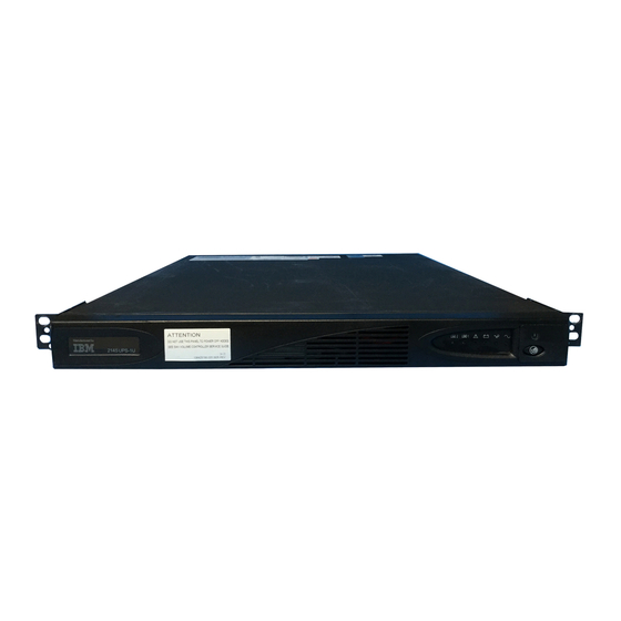
Page 123: The 2145 Ups-1U Front Panel Assembly
Figure 56. 2145 UPS-1U (rear view) Mains power connector Communication port Load segment 2 receptacle Attention: Ensure that you comply with the following requirements: v The voltage supplied to the 2145 UPS-1U must be 200 – 240 V single phase. v The frequency supplied must be 50 or 60 Hz. -
Page 124: Ups-1U Power Cable Retention Bracket
4. Position the bracket with the power cable protruding through the rightmost slot in the bracket. 5. Secure the bracket in place with one screw on each side, as shown in Figure 59 on page 87. IBM System Storage SAN Volume Controller: Hardware Installation Guide... -
Page 125: Installing The San Volume Controller 2145-8F4 Or The San Volume Controller 2145-8F2
Figure 59. 2145 UPS-1U power cable retention bracket Installing the SAN Volume Controller 2145-8F4 or the SAN Volume Controller 2145-8F2 There are several steps that you must perform to install the SAN Volume Controller 2145-8G4 node. Installing the SAN Volume Controller 2145-8F4 or the SAN Volume Controller 2145-8F2 consists of the following tasks: 1. -
Page 126: Retracting The Latch Lock Carrier
(Figure 61). The latch-lock carrier assembly slides against the spring tension. Figure 61. Opening the front latch-lock carrier assembly Latch-lever Latch-lock IBM System Storage SAN Volume Controller: Hardware Installation Guide... -
Page 127: Opening The Back Latch-Lock Carrier Assembly
4. Continue to slide the latch-lock carrier for approximately 13 mm (0.5 in). The latch-lever engages a hole in the back bracket assembly and holds the latch-lock carrier in the retracted position. 5. Push the back rail bracket (Figure 62) toward the front of the rail until it stops. -
Page 128: Installing The Front End Of The Rail
Important: Ensure that the locating pins are fully extended through the front rail bracket. IBM System Storage SAN Volume Controller: Hardware Installation Guide... -
Page 129: Closing The Latch-Lock Carrier Assembly
Figure 64. Closing the latch-lock carrier assembly Latch-lever Latch-lock 9. Push the back rail bracket toward the rear of the rack and align the locating pins with the rack-mounting flange. 10. Push the latch lock away from the rail to release the carrier. The latch-lock carrier slides toward the rear of the rack, and the locating pins project through the holes that are in the rear flange and in the rear rail bracket. -
Page 130: Connecting The San Volume Controller 2145-8F4
Before you begin this task, see the user’s cable connection table, which is provided in the IBM System Storage SAN Volume Controller: Planning Guide and is also available at http://www.ibm.com/storage/support/2145. Use this table to identify the 2145 UPS-1U to which this SAN Volume Controller 2145-8F4 or SAN Volume Controller 2145-8F2 is to be connected. -
Page 131: Connecting The San Volume Controller 2145-8F2 Power Cable To The 2145 Ups-1U
ATTENTION CONNECT ONLY IBM SAN VOLUME CONTROLLERS TO THESE OUTLETS. SEE SAN VOLUME CONTROLLER INSTALLATION GUIDE. Figure 65. Connecting the SAN Volume Controller 2145-8F2 power cable to the 2145 UPS-1U Fibre-channel ports Power connector Serial connector Ethernet ports Main power connector... -
Page 132: Connecting The San Volume Controller 2145-8F4 Or The San Volume Controller 2145-8F2 To The San And To The Ethernet Network
Figure 68 on page 95 or Figure 69 on page 95. Attention: You must use only Ethernet port 1 on the SAN Volume Controller. The software is configured only for Ethernet port 1. IBM System Storage SAN Volume Controller: Hardware Installation Guide... -
Page 133: Verifying The San Volume Controller 2145-8F4 Or The San Volume Controller 2145-8F2 Installation
2. Connect the other end of the Ethernet cable to the proper connector on the Ethernet hub or switch. Figure 68. Connectors at the back of the SAN Volume Controller 2145-8F4 Fibre-channel port 1 Fibre-channel port 2 Fibre-channel port 3 Fibre-channel port 4 Ethernet port 1 Figure 69. -
Page 134: Front Panel Display When Push Buttons Are
1. Press the SAN Volume Controller power switch. Verify that the green power light is on. If the light is not on, see “MAP 5000: Start” in the IBM System Storage SAN Volume Controller: Service Guide to repair the problem. -
Page 135: Node Number
9. Check whether the second line of the front-panel display shows the message Active. If Active is not shown on the second line, go to “MAP 5600: Fibre channel” in the IBM System Storage SAN Volume Controller: Service Guide to repair the fault. -
Page 136: Installing The Hardware Master Console
Cluster: and the progress bar no longer displays. The installation of the SAN Volume Controller hardware is now complete. No software installation is required. Continue with the instructions in the IBM System Storage SAN Volume Controller: Software Installation and Configuration Guide to, if necessary, create a new SAN Volume Controller cluster and to add the nodes into a SAN Volume Controller cluster. - Page 137 If there are any devices directly above and below the master console server unit, it might be very difficult to reach in and connect the cables to the back of the server after it is placed in the rack. If that is the only slot available, connect the keyboard, mouse, monitor, and Ethernet cables at the back of the master console server before installing it in the rack.
- Page 138 IBM System Storage SAN Volume Controller: Hardware Installation Guide...
-
Page 139: Appendix B. San Volume Controller 2145-4F2
Environment requirements without redundant ac power Maximum wet Relative bulb Environment Temperature Altitude humidity temperature Operating in 10°C to 35°C 0 to 914 m 8% to 80% 23°C (74°F) lower altitudes (50°F to 95°F) (0 to 2998 ft) noncondensing © Copyright IBM Corp. 2003, 2007... - Page 140 (27 in.) (28 lb) Additional space requirements Additional space Location requirements Reason Left and right sides 50 mm Cooling air flow (2 in.) Back Minimum: Cable exit 100 mm (4 in.) IBM System Storage SAN Volume Controller: Hardware Installation Guide...
-
Page 141: San Volume Controller 2145-4F2 Controls And Indicators
To turn off the power, press and release the power button. For a preferred method of powering off, see the “Powering off a SAN Volume Controller node” topic in the IBM System Storage SAN Volume Controller: Service Guide. Note: When the SAN Volume Controller is operational and the power control button is pressed, the SAN Volume Controller indicates on its front panel that it is powering off and writes its control data to its internal disk. -
Page 142: Power Led
Note: The select button is used in tandem with the navigation buttons. Select button You can use the select button to select an item from a menu. IBM System Storage SAN Volume Controller: Hardware Installation Guide... -
Page 143: Front Panel Display
The select button and navigation buttons help you to navigate and select menu and boot options, and start a service panel test. The select button is located on the front panel of the SAN Volume Controller, near the navigation buttons. Front panel display The front panel display shows service, configuration, and navigation information. -
Page 144: System Board Power Led
This LED is illuminated when a good Ethernet connection exists between the SAN Volume Controller 2145-4F2 and the Ethernet network. Ethernet port 2 is not used on the SAN Volume Controller. IBM System Storage SAN Volume Controller: Hardware Installation Guide... -
Page 145: San Volume Controller 2145-4F2 Connectors
SAN Volume Controller 2145-4F2 connectors The external connectors for the SAN Volume Controller can be located easily. Context Figure 73 provides the locations of the external connectors. Figure 73. SAN Volume Controller 2145-4F2 connector locations Power connector fibre-channel port 3 fibre-channel port 4 Ethernet port 2 (not used on the SAN Volume Controller 2145-4F2) Ethernet port 1... -
Page 146: 2145 Ups Configuration
UPSs in the same I/O group, you must connect these nodes to different 2145 UPSs. This configuration ensures that cache and cluster state information is protected in the event of a failure of either the UPS or the mainline power source. IBM System Storage SAN Volume Controller: Hardware Installation Guide... -
Page 147: 2145 Ups Environment
2145 UPS environment Ensure that your physical site meets the installation requirements of the 2145 uninterruptible power supply (2145 UPS). UPS specifications Attention: Ensure that you comply with the following requirements for the 2145 UPS units: v If the UPS is cascaded from another UPS, the source UPS must have at least three times the capacity per phase and the total harmonic distortion must be less than 5%. -
Page 148: Off Button
To turn off the power, press and hold the off button until the long beep stops (approximately five seconds). The mode indicator starts to flash and the 2145 UPS remains in standby mode until you disconnect the 2145 UPS from the main power outlet. IBM System Storage SAN Volume Controller: Hardware Installation Guide... -
Page 149: Hardware For The 2145 Ups
Load-level indicators The load-level indicators show the percentage of the 2145 uninterruptible power supply (2145 UPS) capacity that the SAN Volume Controller 2145-4F2 is using. When all the indicators are lit, the power requirements of the SAN Volume Controller 2145-4F2 have exceeded the capacity of the 2145 UPS. Site wiring fault indicator The site wiring fault indicator on the 2145 uninterruptible power supply (2145 UPS) shows that either a ground wire connection does not exist or the live and... - Page 150 Signal cable connectors Main power connector Output connectors Circuit breakers Hardware locations for the 2145 UPS Battery assembly Frame assembly Electronics assembly Front panel assembly 2145 UPS connector Neutral Ground Live IBM System Storage SAN Volume Controller: Hardware Installation Guide...
-
Page 151: Power Cables For The 2145 Ups
Power cables for the 2145 UPS You must follow the power requirements of your country or region to choose the appropriate power cable for the 2145 uninterruptible power supply (2145 UPS). The following table lists the power cable requirements for your country or region: Country or region Length Connection type... -
Page 152: Installing The San Volume Controller 2145-4F2 Hardware
(2145 UPS-1U). Complete the following prerequisites before installing the support rails: 1. Use the user’s hardware location chart to determine where in the rack that the 2145 UPS-1U is to be installed. IBM System Storage SAN Volume Controller: Hardware Installation Guide... - Page 153 2. At the back of the rack, observe the Electronic Industries Alliance (EIA) positions and determine where you are going to install the 2145 UPS-1U. Because of its weight, position the 2145 UPS-1U where it is easy to handle in one of the lower positions in the rack.
- Page 154 9. Install a clip nut in the top hole of the rail 10. Repeat step 7 on page 81 through step 9 on page 82 for the other rail. 11. Tighten the assembly wing nuts on both rail assemblies. IBM System Storage SAN Volume Controller: Hardware Installation Guide...
- Page 155 Use the reference numbers in parentheses at the end of each notice to find the matching translated notice. For the translation of the danger, caution, attention notices, and the translation of the safety labels, see the IBM Systems Safety Notices.
- Page 156 3. If you have not already connected the internal battery connector, remove the 2145 UPS-1U front panel. Figure 78. Removing the 2145 UPS-1U front panel 4. Remove the protective label from the internal battery connector. IBM System Storage SAN Volume Controller: Hardware Installation Guide...
- Page 157 Figure 79. The 2145 UPS-1U internal battery connector with protective tape 5. Connect the internal battery connector. Each end of the keyed connector has two wires: one red (+) and one black (−). Join the black wires and the red wires together.
- Page 158 Take no action for this alarm condition unless it persists for more than five minutes after a SAN Volume Controller has been connected to this 2145 UPS-1U and powered on. IBM System Storage SAN Volume Controller: Hardware Installation Guide...
-
Page 159: Installing The 2145 Ups
Use the user’s hardware location chart, which you downloaded from http://www.ibm.com/storage/support/2145, to determine where in the rack that you want to install the 2145 UPS. v Discard the two handles and their associated nuts that are shipped with the support rails. - Page 160 IBM System Storage SAN Volume Controller: Hardware Installation Guide...
- Page 161 Use the reference numbers in parentheses at the end of each notice to find the matching translated notice. For the translation of the danger, caution, attention notices, and the translation of the safety labels, see the IBM Systems Safety Notices.
- Page 162 Figure 85. Sliding the 2145 UPS to the end of the carton. c. Remove the two bolts and additional nut on the left side of the bracket, as shown in Figure 86 on page 125. Next, remove the battery retaining bracket IBM System Storage SAN Volume Controller: Hardware Installation Guide...
- Page 163 Figure 86. Fastening the battery retaining bracket Bolts Battery retaining bracket d. Grip the tab on the front of the battery and pull the battery forward until it can be accessed by two service representatives. e. With the assistance of another service representative, lift the battery assembly clear of the 2145 UPS and place to one side.
- Page 164 2145 UPS onto the support rails and then slide it into the rack. 6. Install the front flathead screws ( in Figure 88 on page 127). IBM System Storage SAN Volume Controller: Hardware Installation Guide...
- Page 165 Figure 88. Installing the 2145 UPS into a rack Front flathead screws 7. With the assistance of another service representative, reinstall the following parts: a. Battery assembly b. Battery retaining bracket c. Electronics assembly Attention: A grounding screw feature is provided on the back of the 2145 UPS so that you can attach a ground bonding wire, if it is required by local wiring codes.
- Page 166 When a SAN Volume Controller 2145-4F2 is connected to the 2145 UPS, the SAN Volume Controller 2145-4F2 IBM System Storage SAN Volume Controller: Hardware Installation Guide...
-
Page 167: Installing The San Volume Controller 2145-4F2
automatically adjusts the voltage range setting. Take no action for this alarm condition unless it persists for more than five minutes after a SAN Volume Controller 2145-4F2 has been connected to this 2145 UPS and powered on. 11. Repeat all of these steps to install additional 2145 UPSs. Installing the SAN Volume Controller 2145-4F2 There are several steps that you must perform to install the SAN Volume Controller 2145-4F2 node. - Page 168 (Figure 93) toward the front of the rail until it stops. The rail is now at its shortest adjustment. Figure 93. Opening the back latch-lock carrier assembly Back rail bracket Latch-lock IBM System Storage SAN Volume Controller: Hardware Installation Guide...
- Page 169 Latch-lever 6. Place the front end of the left rail in the rack cabinet. Align the top of the front bracket (Figure 94) with the required EIA marking that is on the rack. Figure 94. Installing the front end of the rail Front bracket Rack-mounting flange Locating pins...
- Page 170 Perform the following steps to install the SAN Volume Controller 2145-4F2 node in the rack: 1. Stand at the front of the rack and place the back of the node onto the support rails, as low in the rack as possible. IBM System Storage SAN Volume Controller: Hardware Installation Guide...
-
Page 171: Connecting The San Volume Controller 2145-4F2 To The 2145 Ups-1U
Before you begin this task, see the user’s cable connection table, which is described in the IBM System Storage SAN Volume Controller: Planning Guide and is available at http://www.ibm.com/storage/support/2145. Use this table to identify the 2145 UPS-1U to which this node is to be connected. -
Page 172: Connecting The San Volume Controller 2145-4F2 To The 2145 Ups
Each SAN Volume Controller 2145-4F2 of a pair must be connected to a different 2145 UPS. Each 2145 UPS can support up to two SAN Volume Controller 2145-4F2s. IBM System Storage SAN Volume Controller: Hardware Installation Guide... - Page 173 2145 UPSs. Before you begin this task, refer to the user’s cable connection table, which you downloaded from http://www.ibm.com/storage/support/2145, to identify the 2145 UPS that you want this SAN Volume Controller 2145-4F2 to connect to.
-
Page 174: Connecting The San Volume Controller 2145-4F2 To The San And To The Ethernet Network
4. Connect the other ends of the fibre-channel cables to the proper connectors of the fibre-channel switches. Complete steps 1 through 4 for each node that you need to connect to the SAN and to the Ethernet network. IBM System Storage SAN Volume Controller: Hardware Installation Guide... -
Page 175: Verifying The San Volume Controller 2145-4F2 Installation
1. Press the SAN Volume Controller power switch. Verify that the green power light is on. If the light is not on, see “MAP 5000: Start” in the IBM System Storage SAN Volume Controller: Service Guide to repair the problem. - Page 176 9. Check whether the second line of the front-panel display shows the message Active. If Active is not shown on the second line, go to “MAP 5600: Fibre channel” in the IBM System Storage SAN Volume Controller: Service Guide to repair the fault.
-
Page 177: Installing The Hardware Master Console
Cluster: and the progress bar no longer displays. The installation of the SAN Volume Controller hardware is now complete. No software installation is required. Continue with the instructions in the IBM System Storage SAN Volume Controller: Software Installation and Configuration Guide to, if necessary, create a new SAN Volume Controller cluster and to add the nodes into a SAN Volume Controller cluster. - Page 178 Note: It is important that you do this step; otherwise, the user is not presented later with the choice to accept or decline Windows registration conditions. 6. Connect the master console to the Ethernet port that is designated in the Cable connection table. IBM System Storage SAN Volume Controller: Hardware Installation Guide...
-
Page 179: Appendix C. Using The Front Panel Of The San Volume Controller
F a i l e d 1 8 0 See the topic that contains the boot codes in the IBM System Storage SAN Volume Controller: Service Guide where you can find a description of the failure and the appropriate steps that you must perform to correct the failure. -
Page 180: Error Codes
When the progress bar reaches zero, the node powers off. Note: When input power is restored to the uninterruptible power supply, the SAN Volume Controller turns on without the front panel power button being pressed. IBM System Storage SAN Volume Controller: Hardware Installation Guide... -
Page 181: Powering Off
P o w e r F a i l u r e Powering off The progress bar on the display shows the progress of the power-off operation. The Powering-off display shows that the power button has been pressed and the node is powering off. -
Page 182: Shutting Down
Note: Messages might not display fully on the screen. You might see a right angle bracket (>) on the right-hand side of the display screen. If you see a right angle bracket, press the Right arrow button to scroll through the display. IBM System Storage SAN Volume Controller: Hardware Installation Guide... -
Page 183: Cluster Options
This action displays the rest of the text. Press the Left arrow button to scroll back. When there is no more text to display, you can move to the next item in the menu by pressing the Right arrow button. There are five main options available: v Cluster v Node... -
Page 184: Node Options
Service Access Figure 104. Recover Cluster? menu sequence You do not need to use this field during installation. For more information about the Recover cluster? field, see the IBM System Storage SAN Volume Controller: Service Guide. Node options The node option displays the identification number or name of the SAN Volume Controller. - Page 185 v The SAN Volume Controller is not operational. A hardware fault is preventing the SAN Volume Controller from being part of a cluster. Create cluster? Clusters can be created from the Create Cluster menu. The Create cluster? field allows you to create a new SAN Volume Controller cluster.
- Page 186 If you change the gateway address, ensure that you type the correct address. Otherwise, you cannot access the cluster from the Web interface or from a command line. Perform the following steps to change the gateway address: IBM System Storage SAN Volume Controller: Hardware Installation Guide...
- Page 187 1. Press the select button. The first gateway address number field is highlighted. 2. Press the up button if you want to increase the value that is displayed; press the down button if you want to decrease that value. If you want to quickly increase the highlighted value, hold the up button.
-
Page 188: Ethernet Option
The Select language? option allows you to change the language that is displayed on the menu. Figure 106 shows the Select language? option sequence. Select Language? Select English Portugu s (Brazil) ê Fran ais ç Deutsch Figure 106. Select language? menu sequence IBM System Storage SAN Volume Controller: Hardware Installation Guide... - Page 189 Press the right button to display the language that you want. When the required language is displayed, press the select button. Note: Line 1 of the menu displays an option. For some options, additional data is displayed on line 2. If, the front panel is set to Japanese, Korean, or Chinese, the menu shows only line 1.
- Page 190 IBM System Storage SAN Volume Controller: Hardware Installation Guide...
-
Page 191: Accessibility
Web site: http://www.ibm.com/storage/support/2145 Related reference “SAN Volume Controller library and related publications” on page xii A list of other publications that are related to this product are provided to you for your reference. © Copyright IBM Corp. 2003, 2007... - Page 192 IBM System Storage SAN Volume Controller: Hardware Installation Guide...
-
Page 193: Notices
Web sites. The materials at those Web sites are not part of the materials for this IBM product and use of those Web sites is at your own risk. - Page 194 IBM may use or distribute any of the information you supply in any way it believes appropriate without incurring any obligation to you. Licensees of this program who wish to have information about it for the purpose of enabling: (i) the exchange of information between independently created...
-
Page 195: Trademarks
BladeCenter v Enterprise Storage Server v FlashCopy v IBM v IBM eServer v IBM TotalStorage v IBM System Storage v System p5 v System z9 v System Storage v TotalStorage v xSeries Intel and Pentium are trademarks of Intel Corporation in the United States, other countries, or both. -
Page 196: Industry Canada Compliance Statement
IBM cannot accept responsibility for any failure to satisfy the protection requirements resulting from a nonrecommended modification of the product, including the fitting of non-IBM option cards. This product has been tested and found to comply with the limits for Class A Information Technology Equipment according to European Standard EN 55022. -
Page 197: Germany Compliance Statement
Klasse A ein. Um dieses sicherzustellen, sind die Geräte wie in den Handbüchern beschrieben zu installieren und zu betreiben. Des Weiteren dürfen auch nur von der IBM empfohlene Kabel angeschlossen werden. IBM übernimmt keine Verantwortung für die Einhaltung der Schutzanforderungen, wenn das Produkt ohne Zustimmung der IBM verändert bzw. -
Page 198: Japanese Voluntary Control Council For Interference (Vcci) Statement
Verantwortlich für die Konformitätserklärung des EMVG ist die IBM Deutschland GmbH, 70548 Stuttgart. Generelle Informationen: Das Gerät erfüllt die Schutzanforderungen nach EN 55024 und EN 55022 Klasse Japanese Voluntary Control Council for Interference (VCCI) statement People’s Republic of China Class A Electronic Emission... -
Page 199: Taiwan Class A Compliance Statement
Fax: 0049 (0)711 785 1283 e-mail: mailto:tjahn@de.ibm.com Taiwan Contact Information This topic contains the product service contact information for Taiwan. IBM Taiwan Product Service Contact Information: IBM Taiwan Corporation 3F, No 7, Song Ren Rd., Taipei Taiwan Tel: 0800-016-888 Notices... - Page 200 IBM System Storage SAN Volume Controller: Hardware Installation Guide...
-
Page 201: Glossary
Glossary This glossary includes terms for the IBM System Storage SAN Volume Controller. This glossary includes selected terms and definitions from A Dictionary of Storage Networking Terminology (http://www.snia.org/education/dictionary), copyrighted 2001 by the Storage Networking Industry Association, 2570 West El Camino Real, Suite 304, Mountain View, California 94040-1313. Definitions derived from this book have the symbol (S) after the definition. - Page 202 Write cache holds data written by a client until it can be safely stored on more permanent storage media such as disk or tape. Call Home A communication service that links a machine to a service provider. The IBM System Storage SAN Volume Controller: Hardware Installation Guide...
- Page 203 IBM or to another service provider when service is required. With access to the machine, service personnel can perform service tasks, such as viewing error and problem logs or initiating trace and dump retrievals.
- Page 204 Pertaining to a valid configuration that has suffered a failure but continues to be supported and legal. Typically, a repair action can be performed on a degraded configuration to restore it to a valid configuration. IBM System Storage SAN Volume Controller: Hardware Installation Guide...
- Page 205 In the CIM Agent, the storage server that processes and hosts client application requests. IBM definition: A piece of equipment that is used with the computer and does not generally interact directly with the system, but is controlled by a controller.
- Page 206 A fabric can consist of more than one switch. When multiple fibre-channel switches are interconnected, they are described as cascading. See also cascading. IBM System Storage SAN Volume Controller: Hardware Installation Guide...
- Page 207 (FRU) An assembly that is replaced in its entirety when any one of its components fails. An IBM service representative performs the replacement. In some cases, a field replaceable unit might contain other field replaceable units.
- Page 208 Hubs maintain the logical loop topology of the network of which they are a part, while creating a “hub and spoke” physical star layout. Unlike IBM System Storage SAN Volume Controller: Hardware Installation Guide...
- Page 209 switches, hubs do not aggregate bandwidth. Hubs typically support the addition or removal of nodes from the bus while it is operating. (S) Contrast with switch. See identifier. identifier (ID) A sequence of bits or characters that identifies a user, program device, or system to another user, program device, or system.
- Page 210 Internet. For example, 9.67.97.103 is an IP address. See interswitch link. ISL hop Considering all pairs of node ports (N-ports) in a fabric and measuring distance only in terms of interswitch links (ISLs) in the fabric, the number IBM System Storage SAN Volume Controller: Hardware Installation Guide...
- Page 211 ISLs traversed is the number of ISL hops on the shortest route between the pair of nodes that are farthest apart in the fabric. JBOD (just a bunch of disks) IBM definition: See non-RAID. HP definition: A group of single-device logical units not configured into any other container type.
- Page 212 See FlashCopy mapping. master console A single point from which to manage the IBM System Storage SAN Volume Controller. The master console can be purchased as software that is installed and configured on a server or as a hardware platform with the operating system and master console software preinstalled.
- Page 213 namespace The scope within which a Common Information Model (CIM) schema applies. node One SAN Volume Controller. Each node provides virtualization, cache, and Copy Services to the storage area network (SAN). node name A name identifier associated with a node. (SNIA) node port (N_port) A port that connects a node to a fabric or to another node.
- Page 214 See also symmetrical network. partition IBM definition: A logical division of storage on a fixed disk. HP definition: A logical division of a container represented to the host as a logical unit.
- Page 215 RAID See redundant array of independent disks. RAID 0 IBM definition: RAID 0 allows a number of disk drives to be combined and presented as one large disk. RAID 0 does not provide any data redundancy. If one drive fails, all data is lost.
- Page 216 SNIA dictionary definition: A form of storage array in which two or more identical copies of data are maintained on separate media. (S) IBM definition: A form of storage array in which two or more identical copies of data are maintained on separate media. Also known as mirrorset.
- Page 217 relationship In Metro or Global Mirror, the association between a master virtual disk (VDisk) and an auxiliary VDisk. These VDisks also have the attributes of a primary or secondary VDisk. See also auxiliary virtual disk, master virtual disk, primary virtual disk, and secondary virtual disk. reliability The ability of a system to continue to return data even if a component fails.
- Page 218 A configuration command that is used to stop the activity for all copy relationships in a consistency group. stopped The status of a pair of virtual disks (VDisks) that have a copy relationship that the user has temporarily broken because of a problem. IBM System Storage SAN Volume Controller: Hardware Installation Guide...
- Page 219 (MDisks) that are in the MDisk group. Extents are allocated on the MDisks in the order specified. stripeset See RAID 0. subsystem device driver (SDD) An IBM pseudo device driver designed to support the multipath configuration environments in IBM products. superuser authority The level of access required to add users. suspended The status of a pair of virtual disks (VDisks) that have a copy relationship that has been temporarily broken because of a problem.
- Page 220 It does not deal with questions of physical location of components or interconnecting cables. (S) IBM TotalStorage Enterprise Storage Server (ESS) An IBM product that provides an intelligent disk-storage subsystem across an enterprise. trigger To initiate or reinitiate copying between a pair of virtual disks (VDisks) that have a copy relationship.
- Page 221 valid configuration A configuration that is supported. VDisk See virtual disk. virtual disk (VDisk) In SAN Volume Controller, a device that host systems attached to the storage area network (SAN) recognize as a Small Computer System Interface (SCSI) disk. virtualization In the storage industry, a concept in which a pool of storage is created that contains several disk subsystems.
- Page 222 In fibre-channel environments, the grouping of multiple ports to form a virtual, private, storage network. Ports that are members of a zone can communicate with each other, but are isolated from ports in other zones. IBM System Storage SAN Volume Controller: Hardware Installation Guide...
-
Page 223: Index
SAN Volume Controller 2145-8G4 12 shortcut keys 153 console application programming interface 6 master 31 SAN Volume Controller danger notices master console 5 2145 UPS-1U 54, 133 user interface 6 definition of xvii redundant ac power switch 37 © Copyright IBM Corp. 2003, 2007... - Page 224 10, 71, 105 SAN Volume Controller 2145-8F2 Union IEC (International Electrotechnical ac and dc LEDs 74 electronic emission notice 158 Commission) electronic emission not used 73 EMC Directive conformance notice 160 statement 158 IBM System Storage SAN Volume Controller: Hardware Installation Guide...
- Page 225 146 ac and dc 12, 74 SAN Volume Controller status 146 Ethernet 2145-8G4 35, 49 non-IBM Alteration form xviii activity 11 master console 61, 98, 139 not used link 11, 73 redundant ac power switch 2145 UPS-1U ports 26...
- Page 226 SAN Volume Controller ac voltage 14 weight and dimensions 101 2145-4F2 107 electrical 14 SAN Volume Controller 2145-8F2 SAN Volume Controller power 14 air temperature 65 2145-8F4 75 power cables 28, 113 IBM System Storage SAN Volume Controller: Hardware Installation Guide...
- Page 227 SAN Volume Controller 2145-8F2 SAN Volume Controller 2145-8G4 (continued) air temperature 14 Taiwan connecting cable retention bracket 55 contact information 161 ethernet 94 connecting electronic emission notice 161 to a SAN 94 ethernet 58 test and alarm-reset button 25 to the 2145 UPS-1U 92 to a SAN 58 text emphasis xi connectors 77...
- Page 228 IBM System Storage SAN Volume Controller: Hardware Installation Guide...
- Page 229 IBM business partner, or your authorized remarketer. When you send comments to IBM, you grant IBM a nonexclusive right to use or distribute your comments in any way it believes appropriate without incurring any obligation to you. IBM or any other organizations will only use the personal information that you supply to contact you about the issues that you state on this form.
- Page 230 Readers’ Comments — We’d Like to Hear from You Cut or Fold Along Line GC27-2132-01 Fold and Tape Please do not staple Fold and Tape _ _ _ _ _ _ _ _ _ _ _ _ _ _ _ _ _ _ _ _ _ _ _ _ _ _ _ _ _ _ _ _ _ _ _ _ _ _ _ _ _ _ _ _ _ _ _ _ _ _ _ _ _ _ _ _ _ _ _ _ _ _ _ _ _ _ _ _ _ _ _ _ _ _ _ _ _ _ _ _ _ _ _ _ _ _ _ _ _ NO POSTAGE NECESSARY IF MAILED IN THE...
- Page 232 Part Number: 31P1046 Printed in USA GC27-2132-01...