Chapters
Table of Contents
Troubleshooting

Related Manuals for Agilent Technologies E3647A


Summary of Contents for Agilent Technologies E3647A
- Page 1 User’s Guide Part Number: E3646-90001 May 2011. For Warranty information, refer to the back of the manual. © Copyright Agilent Technologies, Inc. 2000 – 2011 All Rights Reserved. Agilent E364xA Dual Output DC Power Supplies Agilent Technologies...
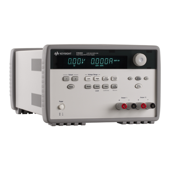
- Page 3 The Agilent Technologies E3646A/E3647A (30 watt) and E3648A/E3649A (50 watt) are high performance dual-output dual range programmable DC power supplies with GPIB and RS-232 interfaces. The combination of bench-top and system features in these power supplies provides versatile solutions for your design and test requirements.
-
Page 4: The Front Panel At A Glance
The Front Panel at a Glance 1 Output1 selection Key 9 Knob 2 Output2 selection Key 10 Output On / Off Key 3 Low voltage range selection Key 11 I/O Configuration Menu / Secure Key 4 High voltage range selection Key 12 View Menu / Calibrate Key 5 Overvoltage protection Key 13 State Storage Menu / Local Key... - Page 5 Front-Panel Menu/Key Reference This section gives an overview of the front-panel keys/menus. The menus are designed to automatically guide you through all parameters required to configure a particular function or operation. 1 Output1 selection key Select the output1 voltage and current to be controlled and monitored on the display.
- Page 6 Front-Panel Voltage and Current Limit Settings You can set the voltage and current limit values from the front panel using the following method. Use the voltage/current adjust selection key, the resolution selection keys, and the control knob to change the voltage and current limit values. High 1 Select the desired output and voltage range using the output selection keys and voltage range selection keys after turning on the power supply.
-
Page 7: Display Annunciators
The power supply is in constant current mode. TRACK The output1 and output2 are in track mode. To review the display annunciators, hold down key as you turn on Display Limit the power supply. *For E3646A/48A models. **For E3647A/49A models. - Page 8 The Rear Panel at a Glance 1 AC inlet 5 Output 2 Rear output terminals 2 Power-line fuse-holder assembly 6 GPIB (IEEE-488) interface connector 3 Power-line module 7 RS-232 interface connector 4 Output 1 Rear output terminals Use the front-panel key to: Config •...
- Page 9 1-800-829-4444 in the United States, or contact your nearest Agilent Technologies Sales Office. If your power supply fails within one year of purchase, Agilent will repair or replace it free of charge. Call 1-800-258-5165 ("Express Exchange") in the United States, or contact your nearest Agilent Technologies Sales Office.
-
Page 10: Declaration Of Conformity
January 1, 2004 Date Bill Darcy/ Regulations Manager For further information, please contact your local Agilent Technologies sales office, agent or distributor, or Agilent Technologies Deutschland GmbH, Herrenberger Stra β e 130, D71034 Böblingen, Germany Revision: B.00.00 Issue Date: Created on 11/24/2003 3:07... -
Page 11: Table Of Contents
Contents Chapter 1 Quick Start Preliminary Checkout- - - - - - - - - - - - - - - - - - - - - - - - - - - - - - - - 17 Output Checkout - - - - - - - - - - - - - - - - - - - - - - - - - - - - - - - - - - - 18 Voltage Output Checkout- - - - - - - - - - - - - - - - - - - - - - - - - - - 18 Current Output Checkout - - - - - - - - - - - - - - - - - - - - - - - - - - - 19 If the Power Supply Does Not Turn On - - - - - - - - - - - - - - - - - - - - 20... - Page 12 Contents Programming Overvoltage Protection - - - - - - - - - - - - - - - - - - - - - 52 Setting the OVP Level and Enable the OVP Circuit - - - - - - - - - 52 Checking OVP Operation - - - - - - - - - - - - - - - - - - - - - - - - - - 53 Clearing the Overvoltage Condition - - - - - - - - - - - - - - - - - - - 53 Disabling the Output - - - - - - - - - - - - - - - - - - - - - - - - - - - - - - - - 56...
- Page 13 Contents The SCPI Status Registers- - - - - - - - - - - - - - - - - - - - - - - - - - - - - 98 What is an Event Register?- - - - - - - - - - - - - - - - - - - - - - - - - - 98 What is an Enable Register? - - - - - - - - - - - - - - - - - - - - - - - - - 98 What is a Multiple Logical Output? - - - - - - - - - - - - - - - - - - - - 98 SCPI Status System- - - - - - - - - - - - - - - - - - - - - - - - - - - - - - 100...
- Page 14 Contents Parallel Connections - - - - - - - - - - - - - - - - - - - - - - - - - - - - - 153 Remote Programming - - - - - - - - - - - - - - - - - - - - - - - - - - - - - - 154 Chapter 8 Specifications Performance Specifications- - - - - - - - - - - - - - - - - - - - - - - - - - - 159 Supplemental Characteristics - - - - - - - - - - - - - - - - - - - - - - - - - 161...
- Page 15 Calibration Reference- - - - - - - - - - - - - - - - - - - - - - - - - - - - - - - 192 Agilent Technologies Calibration Services - - - - - - - - - - - - - - 192...
- Page 16 Contents...
- Page 17 Quick Start...
-
Page 18: Quick Start
Quick Start One of the first things you will want to do with your power supply is to become acquainted with the front panel. The exercises in this chapter prepare the power supply for use and help you get familiar with some of its front-panel operations. This chapter is intended for both the experienced and the inexperienced user because it calls attention to certain checks that should be made prior to operation. -
Page 19: Chapter 1 Quick Start Preliminary Checkout
The following steps help you verify that the power supply is ready for use. 1 Check the list of supplied items. Verify that you have received the following items with your power supply. If anything is missing, contact your nearest Agilent Technologies Sales Office. One power cord for your location. This User’s Guide. -
Page 20: Output Checkout
Chapter 1 Quick Start Output Checkout Output Checkout The following procedures check to ensure that the power supply develops its rated outputs and properly responds to operation from the front panel. For complete performance and verification tests, refer to the Service Information. Note: If an error has been detected during the output checkout procedures, the ERROR annunciator will turn on. -
Page 21: Current Output Checkout
Chapter 1 Quick Start Output Checkout Current Output Checkout The following steps check basic current functions with a short across the power supply’s output. Power 1 Turn on the power supply. Make sure that the output is disabled. The annunciator is on 2 Connect a short across (+) and (-) output terminals with an insulated test lead. -
Page 22: If The Power Supply Does Not Turn On
Use the following steps to help solve problems you might encounter when turning on the instrument. If you need more help, refer to chapter 5 for instructions on returning the instrument to Agilent Technologies for service. 1 Verify that there is ac power to the power supply. -
Page 23: Line Voltage Conversion
Chapter 1 Quick Start Line Voltage Conversion Line Voltage Conversion W a r n i n g Shock Hazard Operating personnel must not remove power supply covers. Component replacement and internal adjustments must be made only by qualified service personnel. Line voltage conversion is accomplished by adjusting two components: the line voltage selection switch and the power-line fuse on the rear panel. - Page 24 Chapter 1 Quick Start Line Voltage Conversion 2 Remove the fuse-holder from the 1 Remove the power cord. Remove assembly. the fuse-holder assembly with a flat- blade screwdriver from the rear panel. 4 Replace the fuse-holder assembly in 3 Replace with the correct fuse. rear panel.
-
Page 25: To Rack Mount The Instrument
You can mount the power supply in a standard 19-inch rack cabinet using one of three optional kits available. Instructions and mounting hardware are included with each rack-mounting kit. Any Agilent Technologies System II instrument of the same size can be rack-mounted beside the Agilent E3646A, E3647A, E3648A, or E3649A. - Page 26 Chapter 1 Quick Start To Rack Mount the Instrument To rack mount two instruments of the same depth side-by-side, order lock-link kit 5061-9694 and flange kit 5063-9214. To install two instruments in a sliding support shelf, order support shelf 5063-9256, and slide kit 1494-0015.
-
Page 27: Chapter 2 General Information
General Information... - Page 28 General Information This manual describes the operation of the Agilent Technologies Model E3646A, E3647A, E3648A, and E3649A DC power supplies. This chapter contains a general description of your power supply. This chapter also provides instructions for installation of your power supply and the output connections.
-
Page 29: Safety Considerations
Chapter 2 General Information Safety Considerations Safety Considerations This power supply is a Safety Class I instrument, which means that it has a protective earth terminal. That terminal must be connected to earth ground through a power source with a 3-wire ground receptacle. Before installation or operation, check the power supply and review this manual for safety markings and instructions. -
Page 30: Options And Accessories
Extra English manual set (local language manual files are included on the CD-ROM, Agilent part number 5964-8251) Accessories The accessories listed below may be ordered from your local Agilent Technologies Sales Office either with the power supply or separately. Agilent No. -
Page 31: Description
Chapter 2 General Information Description Description This power supply features a combination of programming capabilities and linear power supply performance that makes it ideal for power systems applications. The power supply may be programmed locally from the front panel or remotely over the GPIB and RS-232 interfaces. - Page 32 Chapter 2 General Information Description When operated over the remote interface, the power supply can be both a listener and a talker. Using an external controller, you can instruct the power supply to set the output and to send the status data back over the GPIB or RS-232.
-
Page 33: Installation
Keep the original packing materials in case the power supply has to be returned to Agilent Technologies in the future. If you return the power supply for service, attach a tag identifying the owner and model number. Also include a brief description of the problem. -
Page 34: Output Connections
Chapter 2 General Information Output Connections Output Connections W a r n i n g Before attempting to connect wires to the rear output terminals, make sure to turn off the power supply first to avoid damage to the circuits being connected. Front panel binding posts are available to connect load wires for bench operation and are paralleled with the rear panel (+) and (-) connections. -
Page 35: Voltage Drops
Chapter 2 General Information Output Connections Voltage Drops The load wires must also be large enough to avoid excessive voltage drops due to the impedance of the wires. In general, if the wires are heavy enough to carry the maximum short circuit current without overheating, excessive voltage drops will not be a problem. -
Page 36: Remote Voltage Sensing Connections
Chapter 2 General Information Output Connections Reverse Current Loading An active load connected to the power supply may actually deliver a reverse current to the supply during a portion of its operating cycle. An external source can not be allowed to pump current into the supply without risking loss of regulation and possible damage. - Page 37 Chapter 2 General Information Output Connections Stability Using remote sensing under certain combinations of load lead lengths and large load capacitances may cause your application to form a filter, which becomes part of the voltage feedback loop. The extra phase shift created by this filter can degrade the power supply’s stability, resulting in poor transient response or loop instability.
-
Page 38: Multiple Loads
Chapter 2 General Information Output Connections Multiple Loads When connecting multiple loads to the power supply, each load should be connected to the output terminals using separate connecting wires. This minimizes mutual coupling effects between loads and takes full advantage of the low output impedance of the power supply. -
Page 39: Chapter 3 Front-Panel Operation And Features
Front-Panel Operation and Features... - Page 40 Front-Panel Operation and Features So far you have learned how to install your power supply and do quick start. During the quick start, you were briefly introduced to operating from the front panel as you learned how to check basic voltage and current functions. This chapter describes in detail the use of the front-panel keys and shows how they are used to accomplish power supply operation.
-
Page 41: Front-Panel Operation Overview
Chapter 3 Front-Panel Operation and Features Front-Panel Operation Overview Front-Panel Operation Overview The following section describes an overview of the front-panel keys before operating your power supply. • The power supply is shipped from the factory configured in the front-panel operation mode. -
Page 42: Constant Voltage Operation
Chapter 3 Front-Panel Operation and Features Constant Voltage Operation Constant Voltage Operation To set up the power supply for constant voltage (CV) operation, proceed as follows. • Front-panel operation: 1 Connect a load to the output terminals. With power-off, connect a load to the (+) and (-) output terminals. Power 2 Turn on the power supply. - Page 43 Chapter 3 Front-Panel Operation and Features Constant Voltage Operation 5 Adjust the knob for the desired output voltage. Check that the annunciator still flashes. Set the knob for voltage control. Change Limit the flashing digit using the resolution selection keys and adjust the knob for the desired output voltage.
-
Page 44: Constant Current Operation
Chapter 3 Front-Panel Operation and Features Constant Current Operation Constant Current Operation To set up the power supply for constant current (CC) operation, proceed as follows. • Front-panel operation: 1 Connect a load to the output terminals. With power-off, connect a load to the (+) and (-) output terminals. Power 2 Turn on the power supply. - Page 45 Chapter 3 Front-Panel Operation and Features Constant Current Operation 5 Adjust the knob for the desired output current. Check that the annunciator still flashes. Set the knob for current control. Change Limit the flashing digit using the resolution selection keys and adjust the knob to the desired output current.
-
Page 46: Tracking Operation
Chapter 3 Front-Panel Operation and Features Tracking Operation Tracking Operation This power supply provides tracking outputs. In the track mode, two voltages of the output1 and the output2 supplies track each other within the voltage programming accuracy as described on page 163 in chapter 8 for convenience in varying the symmetrical voltages needed by operational amplifiers and other circuits using balanced two outputs. -
Page 47: View Menu Operation
Chapter 3 Front-Panel Operation and Features View Menu Operation View Menu Operation From the View menu, you can read the Errors, Firmware Revision, and Calibration String. In addition, you can change the front-panel display mode to V-V display, I-I display, or V-I display as desired. With this V-V or I-I display mode setting, you can see voltages or currents on the output1 and the output2, simultaneously. -
Page 48: Viewing The Errors
Chapter 3 Front-Panel Operation and Features View Menu Operation Viewing the Errors View 1 Press key twice to view the errors. View 1: err -103 Total number of the errors detected will be displayed shortly before the above message is displayed. The above number ‘‘1’’ stands for the first error in queue and the ‘‘-103’’ is error code. -
Page 49: Viewing The Calibration String
Chapter 3 Front-Panel Operation and Features View Menu Operation Viewing the Calibration String View 1 Enter the View menu and select CAL STRING. cal string View 2 Scroll through the text of the message. cal12-24-99 NO STRING is displayed if no calibration message is stored. Press to increase >... -
Page 50: Configuring The Remote Interface
3 Save the change and exit the menu. SAVED N o t e Your computer's GPIB interface card has its own address. Be sure to avoid using the computer's address for any instrument on the interface bus. Agilent Technologies GPIB interface cards generally use address ‘‘21’’. -
Page 51: Rs-232 Configuration
Chapter 3 Front-Panel Operation and Features Configuring the Remote Interface RS-232 Configuration Config 1 Turn on the remote configuration mode. GPIB / 488 Notice that if you changed the remote interface selection to RS-232 before, “RS-232” message is displayed. 2 Choose the RS-232 interface. RS-232 You can choose the RS-232 interface by turning the knob. -
Page 52: Storing And Recalling Operating States
Chapter 3 Front-Panel Operation and Features Storing and Recalling Operating States Storing and Recalling Operating States You can store up to five different operating state in non-volatile storage locations. When shipped from the factory, storage locations ‘‘1’’ through ‘‘5’’ are empty. You can name a location from the front panel or over the remote interface but you can only recall a named state from the front panel. - Page 53 Chapter 3 Front-Panel Operation and Features Storing and Recalling Operating States Store 4 Save the operating state DONE Recalling a Stored State N o t e Before proceeding with the steps listed below, ensure that the outputs are disabled throughout the Recall procedure (the annunciator turns off and the annunciator turns on).
- Page 54 Chapter 3 Front-Panel Operation and Features Storing and Recalling Operating States Store an operating state to a specified location *SAV {1|2|3|4|5} Recall a previously stored state from a specified *RCL {1|2|3|4|5} location ‘‘MEM:STATE:NAME 1, ‘P15V_TEST’’’ Name the storage location 1 as ‘‘P15V_TEST’’.
-
Page 55: Programming Overvoltage Protection
Chapter 3 Front-Panel Operation and Features Programming Overvoltage Protection Programming Overvoltage Protection Overvoltage protection guards the load against output voltages reaching values greater than the programmed protection level. It is accomplished by shorting the output via an internal SCR when the trip level is set to equal or greater than 3 volts, or by programming the output to 1 volt when the trip level is set to less than 3 volts. -
Page 56: Checking Ovp Operation
Chapter 3 Front-Panel Operation and Features Programming Overvoltage Protection Checking OVP Operation To check OVP operation, raise the output voltage to near the trip point. Then very gradually increase the output by turning the knob until the OVP circuit trips. This will cause the power supply output to drop to near zero, the annunciator OVP1... - Page 57 Chapter 3 Front-Panel Operation and Features Programming Overvoltage Protection Over Voltage 4 Clear the overvoltage condition and exit this menu. done The annunciator for OVP operation will not flash any more. The output will return to meter mode. By Adjusting OVP trip level Over Voltage 1 Raise the OVP trip level higher than the level tripped.
- Page 58 Chapter 3 Front-Panel Operation and Features Programming Overvoltage Protection N o t e The power supply’s OVP circuit contains a crowbar SCR, which effectively shorts the output of the power supply whenever the overvoltage condition occurs. If external voltage source such as a battery is connected across the output, and the overvoltage condition inadvertently occurs, the SCR will continuously sink a large current from the source;...
-
Page 59: Disabling The Output
Chapter 3 Front-Panel Operation and Features Disabling the Output Disabling the Output The output of the power supply can be disabled or enabled from the front panel. • When the power supply is in the “Off” state, the annunciator turns on and the output is disabled. -
Page 60: System-Related Operations
Chapter 3 Front-Panel Operation and Features System-Related Operations System-Related Operations This section gives information on system-related topics such as storing power supply states, reading errors, running a self-test, displaying messages on the front panel, and reading firmware revisions. State Storage The power supply has five storage locations in non-volatile memory to store power supply states. -
Page 61: Self-Test
Chapter 3 Front-Panel Operation and Features System-Related Operations • Remote Interface Operation: Use the following commands to store and recall power supply state. *SAV {1|2|3|4|5} *RCL {1|2|3|4|5} To assign a name to a stored state to be recalled from the front panel, send the following command. -
Page 62: Firmware Revision Query
Remote interface operation: *IDN? The above command returns a string in the form: ‘‘Agilent Technologies,E3646A,0,X.X-Y.Y-Z.Z’’ (E3646A) Be sure to dimension a string variable with at least 40 characters. SCPI Language Version This power supply complies with the rules and regulations of the present version of SCPI (Standard Commands for Programmable Instruments). -
Page 63: Gpib Interface Reference
Chapter 3 Front-Panel Operation and Features GPIB Interface Reference GPIB Interface Reference The GPIB connector on the rear panel connects your power supply to the computer and other GPIB devices. Chapter 2 lists the cables that are available from Agilent Technologies. -
Page 64: Rs-232 Configuration Overview
Chapter 3 Front-Panel Operation and Features RS-232 Interface Reference RS-232 Interface Reference The power supply can be connected to the RS-232 interface using the 9-pin (DB-9) serial connector on the rear panel. The power supply is configured as a DTE (Data Terminal Equipment) device. -
Page 65: Connection To A Computer Or Terminal
Chapter 3 Front-Panel Operation and Features RS-232 Interface Reference Connection to a Computer or Terminal To connect the power supply to a computer or terminal, you must have the proper interface cable. Most computers and terminals are DTE (Data Terminal Equipment) devices. -
Page 66: Rs-232 Troubleshooting
Chapter 3 Front-Panel Operation and Features RS-232 Interface Reference DB-25 Serial Connection If your computer or terminal has a 25-pin serial port with a male connector, use the null-modem cable and 25-pin adapter included with the Agilent 34398A Cable Kit. The cable and adapter pin diagram are shown below. 5182-4794 5181-6641 Cable... -
Page 67: Calibration Overview
If you forget your security code, you can disable the security feature by adding a jumper inside the power supply, and then entering a new code. See the Service Information for more information. Table 3-1. Factory setting security codes Model Security Code Model Security Code E3646A 003646 E3647A 003647 E3648A 003648 E3649A 003649... -
Page 68: To Unsecure For Calibration
Chapter 3 Front-Panel Operation and Features Calibration Overview To Unsecure for Calibration You can unsecure the power supply either from the front panel or over the remote interface. The power supply is secured when shipped from the factory. See the table 3-1 for the factory setting secure code for your power supply. -
Page 69: To Secure Against Calibration
Chapter 3 Front-Panel Operation and Features Calibration Overview To Secure Against Calibration You can secure the power supply against calibration either from the front panel or over the remote interface. The power supply is secured when shipped from the factory. Be sure to read the security code rules on page 67 before attempting to secure the power supply. -
Page 70: Calibration Count
Chapter 3 Front-Panel Operation and Features Calibration Overview To Change the Security Code To change the security code, you must first unsecure the power supply, and then enter a new code. Be sure to read the security code rules on page 67 before attempting to secure the power supply. •... -
Page 71: Calibration Message
Chapter 3 Front-Panel Operation and Features Calibration Overview Calibration Message The power supply allows you to store one message in calibration memory in the mainframe. For example, you can store such information as the date when the last calibration was performed, the date when the next calibration is due, the power supply’s serial number, or even the name and phone number of the person to contact for a new calibration. - Page 72 Chapter 3 Front-Panel Operation and Features Calibration Overview...
-
Page 73: Chapter 4 Remote Interface Reference
Remote Interface Reference... - Page 74 Remote Interface Reference • SCPI Command Summary‚ starting on page 75 • Simplified Programming Overview‚ starting on page 81 SCPI • Using the APPLy Command‚ on page 84 • Output Setting and Operation Commands‚ starting on page 85 • Triggering‚ starting on page 91 •...
-
Page 75: Scpi Command Summary
Chapter 4 Remote Interface Reference SCPI Command Summary SCPI Command Summary This section summarizes the SCPI (Standard Commands for Programmable Instruments) commands available to program the power supply over the remote interface. Refer to the later sections in this chapter for more complete details on each command. - Page 76 {<numeric value>|DEFault} VOLTage[:LEVel][:IMMediate]:STEP[:INCRement]? [DEFault] VOLTage[:LEVel]:TRIGgered[:AMPLitude] {<voltage>|MIN|MAX} VOLTage[:LEVel]:TRIGgered[:AMPLitude]? [MIN|MAX] VOLTage:PROTection[:LEVel] {<voltage>|MIN|MAX} VOLTage:PROTection[:LEVel]? [MIN|MAX] VOLTage:PROTection:STATe {0|1|OFF|ON} VOLTage:PROTection:STATe? VOLTage:PROTection:TRIPped? VOLTage:PROTection:CLEar VOLTage:RANGe {P8V*|P20V*|P35V**|P60V**|LOW|HIGH} VOLTage:RANGe? INSTrument[:SELect]{OUTPut1|OUTPut2|OUT1|OUT2} [:SELect]? :NSELect {1|2} :NSELect? :COUPle [:TRIGger] {ON|OFF} [:TRIGger]? MEASure [:SCALar] :CURRent[:DC]? [:VOLTage][:DC]? OUTPut:TRACk[:STATe]{ON|OFF} :TRACk[:STATe]? *For E3646A/48 Models **For E3647A/49A Models...
- Page 77 Chapter 4 Remote Interface Reference SCPI Command Summary Triggering Commands see page 91 for more information INITiate[:IMMediate] TRIGger[:SEQuence] :DELay {<seconds>|MIN|MAX} :DELay?[MIN|MAX] :SOURce {BUS|IMM} :SOURce? *TRG System-Related Commands see page 94 for more information DISPlay[:WINDow] [:STATe] {OFF|ON} [:STATe]? :MODE{VV|VI|II} :MODE? :TEXT[:DATA] <quoted string> :TEXT[:DATA]? :TEXT:CLEar SYSTem...
- Page 78 Chapter 4 Remote Interface Reference SCPI Command Summary Calibration Commands see page 98 for more information CALibration :COUNt? :CURRent[:DATA] <numeric value> :CURRent:LEVel {MIN|MID|MAX} :SECure:CODE <new code> :SECure:STATe {OFF|ON},<quoted code> :SECure:STATe? :STRing <quoted string> :STRing? :VOLTage[:DATA] <numeric value> :VOLTage:LEVel {MIN|MID|MAX} :VOLTage:PROTection Interface Configuration Commands see page 101 for more information SYSTem...
- Page 79 Chapter 4 Remote Interface Reference SCPI Command Summary Status Reporting Commands see page 112 for more information STATus:QUEStionable [:EVENt]? :ENABle <enable value> :ENABle? :INSTrument [:EVENt]? :ENABle <enable value> :ENABle? :ISUMmary<n> [:EVENt]? :CONDition? :ENABle <enable value> :ENABle? SYSTem:ERRor? *CLS *ESE <enable value> *ESE? *ESR? *OPC...
- Page 80 Chapter 4 Remote Interface Reference SCPI Command Summary IEEE-488.2 Common Commands see page 124 for more information *CLS *ESR? *ESE <enable value> *ESE? *IDN? *OPC *OPC? *PSC {0|1} *PSC? *RST *SAV {1|2|3|4|5} *RCL {1|2|3|4|5} *STB? *SRE <enable value> *SRE? *TRG *TST? *WAI...
-
Page 81: Simplified Programming Overview
Chapter 4 Remote Interface Reference Simplified Programming Overview Simplified Programming Overview This section gives an overview of the basic techniques used to program the power supply over the remote interface. This section is only an overview and does not give all of the details you will need to write your own application programs. -
Page 82: Reading A Query Response
Chapter 4 Remote Interface Reference Simplified Programming Overview Reading a Query Response Only the query commands (commands that end with “ ? ”) will instruct the power supply to send a response message. Queries return either output values or internal instrument settings. -
Page 83: Power Supply Programming Ranges
MINimum, MAXimum, DEFault and reset values of your power supply. Refer to this table to identify programming values when programming the power supply. able 4-1. Agilent E3646A/47A/48A/49A Programming Ranges E3646A E3647A E3648A E3649A 0 - 8V/ 0 - 20V/ 0 - 35V/... -
Page 84: Using The Apply Command
Chapter 4 Remote Interface Reference Using the APPLy Command Using the APPLy Command The APPLy command provides the most straightforward method to program the power supply over the remote interface. You can select the output voltage and current in one command. APPLy {<voltage>| DEF | MIN | MAX}[,{<current>| DEF | MIN | MAX}] This command is combination of VOLTage and CURRent commands. -
Page 85: Output Setting And Operation Commands
To set the step size to the minimum resolution, set the step size to ‘‘DEFault’’. The minimum resolution of the step size is approximately 0.052 mA (E3646A), 0.014 mA (E3647A), 0.095 mA (E3648A), and 0.027 mA (E3649A), respectively. The CURR:STEP? DEF returns the minimum resolution of your instrument. The immediate current level increases or decreases by the value of the step size. - Page 86 Chapter 4 Remote Interface Reference Output Setting and Operation Commands CURRent:STEP? [DEFault] Return the value of the step size currently specified. The returned parameter is a numeric value. ‘‘DEFault’’ gives the minimum resolution of the step size in unit of amps.
- Page 87 Chapter 4 Remote Interface Reference Output Setting and Operation Commands INSTrument:NSELect? Return the currently selected output by the INSTrument[SELect]or INSTrument[SELect] command. The returned parameter is ‘‘1’’ for output1, ‘‘2’’ for output2. INSTrument:COUPle[:TRIGger] {ON | OFF} Enable or disable a coupling between two logical outputs of the power supply. The couple command consists of an optional subsystem node followed by a signal parameter.
- Page 88 Chapter 4 Remote Interface Reference Output Setting and Operation Commands MEASure[:VOLTage]? Query the voltage measured at the sense terminals of the power supply. OUTPut:TRACk[:STATe] {ON | OFF} Enable or disable the power supply to operate in the track mode. See “Tracking Operation”...
- Page 89 To set the step size to the minimum resolution, set the step size to ‘‘DEFault’’. The minimum resolution of the step size is approximately 0.35 mV (E3646A), 1.14 mV (E3647A), 0.38 mV (E3648A), and 1.14 mV (E3649A), respectively. The immediate voltage level increases or decreases by the value of the step size. For example, the output voltage will increase or decrease 10 mV if the step size is 0.01.
- Page 90 Chapter 4 Remote Interface Reference Output Setting and Operation Commands VOLTage:PROTection {<voltage>|MINimum|MAXimum} Set the voltage level at which the overvoltage protection (OVP) circuit will trip. If the peak output voltage exceeds the OVP level, then the power supply output is shorted by an internal SCR.
-
Page 91: Triggering
Chapter 4 Remote Interface Reference Triggering Triggering The power supply’s triggering system allows a change in voltage and current when receiving a trigger, to select a trigger source, and to insert a trigger. Triggering the power supply is a multi-step process. •... - Page 92 Chapter 4 Remote Interface Reference Triggering • To ensure synchronization when the bus source is selected, send the *WAI (wait) command. When the *WAI command is executed, the power supply waits for all pending operations to complete before executing any additional commands. For example, the following command string guarantees that the first trigger is accepted and is executed before the second trigger is recognized.
-
Page 93: Triggering Commands
Chapter 4 Remote Interface Reference Triggering Triggering Commands INITiate Cause the trigger system to initiate. This command completes one full trigger cycle when the trigger source is an immediate and initiates the trigger subsystem when the trigger source is bus. TRIGger:DELay {<seconds>| MINimum | MAXimum} Set the time delay between the detection of an event on the specified trigger source and the start of any corresponding trigger action on the power supply output. -
Page 94: System-Related Commands
Chapter 4 Remote Interface Reference System-Related Commands System-Related Commands DISPlay {OFF | ON} Turn the front-panel display off or on. When the display is turned off, outputs are not sent to the display and all annunciators are disabled except the annunciator. - Page 95 The command returns a string with the following format (be sure to dimension a string variable with at least 40 characters): (E3646A model) Agilent Technologies,E3646A,0,X.X-Y.Y-Z.Z *TST? Perform a complete self-test of the power supply. Returns ‘‘0’’ if the self-test passes or ‘‘1’’...
- Page 96 Reset the power supply to its power-on state. The table below shows the state of the power supply after a RESET from the Recall menu or *RST command from the remote interface. Command E3646A E3647A E3648A E3649A state state state...
-
Page 97: State Storage Commands
Chapter 4 Remote Interface Reference State Storage Commands State Storage Commands The power supply has five storage locations in non-volatile memory to store power supply states. The locations are numbered 1 through 5. You can also assign a name to each of the locations (1 through 5) for use from the front panel. *SAV { 1 | 2 | 3 | 4 | 5 } Store (Save) the present state of the power supply to the specified location. -
Page 98: Calibration Commands
Chapter 4 Remote Interface Reference Calibration Commands Calibration Commands See ‘‘Calibration Overview’’, starting on page 67 for an overview of the calibration features of the power supply. An example program for calibration is listed on page 100. For more detailed discussion on the calibration procedures, see the Service Information. - Page 99 Chapter 4 Remote Interface Reference Calibration Commands CALibration:SECure:STATe {OFF | ON},<quoted code> Unsecure or secure the power supply with a security for calibration. CALibration:SECure:STATe? Query the secured state for calibration of the power supply. The returned parameter is ‘‘0’’ (OFF) or ‘‘1’’ (ON). CALibration:STRing <quoted string>...
- Page 100 Chapter 4 Remote Interface Reference Calibration Commands Calibration Example 1 Select the output to be calibrated and enable the output of the power supply by sending the commands: ‘‘ ’’ INST:SEL {OUT1|OUT2} ‘‘ ’’ OUTP ON 2 Disable the voltage protection function. ‘‘...
-
Page 101: Interface Configuration Commands
Chapter 4 Remote Interface Reference Interface Configuration Commands Interface Configuration Commands See also "Configuring the Remote Interface" in chapter 3 starting on page 50. SYSTem:INTerface {GPIB | RS232} Select the remote interface. Only one interface can be enabled at a time. The GPIB interface is selected when the power supply is shipped from the factory. -
Page 102: The Scpi Status Registers
Chapter 4 Remote Interface Reference The SCPI Status Registers The SCPI Status Registers All SCPI instruments implement status registers in the same way. The status system records various instrument conditions in three register groups: the Status Byte register, the Standard Event register, and the Questionable Status register groups. The status byte register records high-level summary information reported in the other register groups. - Page 103 Chapter 4 Remote Interface Reference The SCPI Status Registers Using such a status register configuration allows a status event to be cross-referenced by output and type of event. The INSTrument register indicates which output(s) have generated an event. The ISUMmary register is a pseudo-questionable status register for a particular logical output.
-
Page 104: Scpi Status System
Chapter 4 Remote Interface Reference The SCPI Status Registers SCPI Status System QUEStionable Status Event Register Enable Registers Not Used Output Buffer Not Used Not Used Not Used Temperature Not Used Not Used "OR" Not Used Not Used Not Used Status Byte Not Used Summary Register... -
Page 105: The Questionable Status Register
Chapter 4 Remote Interface Reference The SCPI Status Registers The Questionable Status Register The Questionable Status register provides information about unexpected operation of the power supply. Bit 4 reports a fault with the fan, and bit 13 summarizes questionable outputs for any of the two supplies. For example, if one of the two supplies is in constant voltage mode and due to an overload looses regulation, bit 13 is set (latched). - Page 106 Chapter 4 Remote Interface Reference The SCPI Status Registers The Questionable Instrument Summary Register There are two Questionable Instrument Summary registers, one for each supply output. These registers provide information about voltage and current regulation. Bit 0 is set when the voltage becomes unregulated, and bit 1 is set if the current becomes unregulated.
-
Page 107: The Standard Event Register
Chapter 4 Remote Interface Reference The SCPI Status Registers The Standard Event Register The Standard Event register reports the following types of instrument events: power- on detected, command syntax errors, command execution errors, self-test or calibration errors, query errors, or when an *OPC command is executed. Any or all of these conditions can be reported in the standard event summary bit (ESB, bit 5) of Status Byte register through the enable register. -
Page 108: The Status Byte Register
Chapter 4 Remote Interface Reference The SCPI Status Registers The Standard Event register is cleared when: • You execute the *CLS (clear status) command. • You query the event register using the *ESR? (Event Status register) command. For example, 28 (4 + 8 + 16) is returned when you have queried the status of the Standard Event register, QYE, DDE, and EXE conditions have occurred. -
Page 109: Using Service Request (Srq) And Serial Poll
Chapter 4 Remote Interface Reference The SCPI Status Registers The Status Byte Summary register is cleared when: • You execute the *CLS (clear status) command. • Querying the Standard Event register (*ESR? command) will clear only bit 5 in the Status Byte summary register. For example, 24 (8 + 16) is returned when you have queried the status of the Status Byte register, QUES and MAV conditions have occurred. -
Page 110: Using *Stb? To Read The Status Byte
Chapter 4 Remote Interface Reference The SCPI Status Registers Using *STB? to Read the Status Byte The *STB? (Status Byte query) command is similar to a serial poll but it is processed like any other instrument command. The *STB? command returns the same result as a serial poll but the “request service”... -
Page 111: To Determine When A Command Sequence Is Completed
Chapter 4 Remote Interface Reference The SCPI Status Registers To Determine When a Command Sequence is Completed Send a device clear message to clear the power supply’s output buffer (e.g., CLEAR 705 Clear the event registers with the (clear status) command. *CLS Enable the “operation complete”... -
Page 112: Status Reporting Commands
Chapter 4 Remote Interface Reference Status Reporting Commands Status Reporting Commands See diagram ‘‘SCPI Status System’’, on page 104 in this chapter for detailed information of the status register structure of the power supply. SYSTem:ERRor? Query the power supply’s error queue. A record of up to 20 errors is stored in the power supply’s error queue. - Page 113 Chapter 4 Remote Interface Reference Status Reporting Commands STATus:QUEStionable:INSTrument:ISUMmary<n>[:EVENt]? Return the value of the Questionable Instrument Isummary Event register for a specific output of the two-output power supply. The particular output must be specified by a numeric value. n is 1 or 2. ‘‘1’’ selects output1, and ‘‘2’’ selects output2. The event register is a read-only register which holds (latches) all events.
- Page 114 Chapter 4 Remote Interface Reference Status Reporting Commands *ESR? Query the Standard Event register. The power supply returns a decimal value which corresponds to the binary-weighted sum of all bits in the register. *OPC Set the ‘‘Operation Complete’’ bit (bit 0) of the Standard Event register after the command is executed.
-
Page 115: An Introduction To The Scpi Language
Chapter 4 Remote Interface Reference An Introduction to the SCPI Language An Introduction to the SCPI Language SCPI (Standard Commands for Programmable Instruments) is an ASCII-based instrument command language designed for test and measurement instruments. Refer to ‘‘Simplified Programming Overview’’, starting on page 81 for an introduction to the basic techniques used to program the power supply over the remote interface. -
Page 116: Command Format Used In This Manual
Chapter 4 Remote Interface Reference An Introduction to the SCPI Language Command Format Used in This Manual The format used to show commands in this manual is shown below: CURRent {<current>|MINimum|MAXimum|UP|DOWN} The command syntax shows most commands (and some parameters) as a mixture of upper- and lower-case letters. -
Page 117: Command Separators
Chapter 4 Remote Interface Reference An Introduction to the SCPI Language Command Separators A colon ( : ) is used to separate a command keyword from a lower-level keyword as shown below: ‘‘SOURce:CURRent:TRIGgered’’ A semicolon ( ; ) is used to separate two commands within the same subsystem, and can also minimize typing. -
Page 118: Querying Parameter Settings
Chapter 4 Remote Interface Reference An Introduction to the SCPI Language Querying Parameter Settings You can query the value of most parameters by adding a question mark (?) to the command. For example, the following command sets the output current to 5 amps: ‘‘CURR 5’’... -
Page 119: Scpi Parameter Types
Chapter 4 Remote Interface Reference An Introduction to the SCPI Language SCPI Parameter Types The SCPI language defines several different data formats to be used in program messages and response messages. Numeric Parameters Commands that require numeric parameters will accept all commonly used decimal representations of numbers including optional signs, decimal points, and scientific notation. -
Page 120: Halting An Output In Progress
Chapter 4 Remote Interface Reference Halting an Output in Progress Halting an Output in Progress You can send a device clear at any time to stop an output in progress over the GPIB interface. The status registers, the error queue, and all configuration states are left unchanged when a device clear message is received. -
Page 121: Scpi Conformance Information
Chapter 4 Remote Interface Reference SCPI Conformance Information SCPI Conformance Information The power supply conforms to the ‘1996.0’ version of the SCPI standard. Many of the commands required by the standard are accepted by the power supply but are not described in this manual for simplicity or clarity. - Page 122 :VOLTage[:LEVel][:IMMediate]:STEP[:INCRement]? {DEFault} :VOLTage[:LEVel]:TRIGgered[:AMPLitude] {<voltage>|MIN|MAX} :VOLTage[:LEVel]:TRIGgered[:AMPLitude]?[MIN|MAX] :VOLTage:PROTection[:LEVel] {<voltage>|MIN|MAX} :VOLTage:PROTection[:LEVel]? {MIN|MAX} :VOLTage:PROTection:STATe {0|1|OFF|ON} :VOLTage:PROTection:STATe? :VOLTage:PROTection:TRIPped? :VOLTage:PROTection:CLEar :VOLTage:RANGe {P8V|P20V|LOW|HIGH} (E3646A/48A models) :VOLTage:RANGe {P35V|P60V|LOW|HIGH} (E3647A/49A models) :VOLTage:RANGe? STATus :QUEStionable[:EVENt]? :QUEStionable:ENABle <enable value> :QUEStionable:ENABle? :QUEStionable:INSTrument[:EVENt]? :QUEStionable:INSTrument:ENABle <enable value> :QUEStionable:INSTrument:ENABle? :QUEStionable:INSTrument:ISUMmary<n>[:EVENt]? :QUEStionable:INSTrument:ISUMmary<n>:CONDition? :QUEStionable:INSTrument:ISUMmary<n>:ENABle <enable value> :QUEStionable:INSTrument:ISUMmary<n>:ENABle?
- Page 123 Chapter 4 Remote Interface Reference SCPI Conformance Information Device Specific Commands The following commands are device-specific to your power supply. They are not included in the ‘1997.0’ version of the SCPI standard. However, these commands are designed with the SCPI standard in mind and they follow all of the command syntax rules defined by the standard.
-
Page 124: Ieee-488 Conformance Information
Chapter 4 Remote Interface Reference IEEE-488 Conformance Information IEEE-488 Conformance Information Dedicated Hardware Lines IEEE-488 Common Commands Attention *CLS Interface Clear *ESE < > enable value Remote Enable *ESE? Service Request Enable *ESR? *IDN? *OPC Addressed Commands *OPC? *PSC {0|1} Device Clear *PSC? End or Identify... - Page 125 Error Messages...
-
Page 126: Error Messages
Error Messages Errors are retrieved in first-in-first-out (FIFO) order. The first error returned is the first error that was stored. Errors are cleared as you read them. When you have read all errors from the queue, the annunciator turns off and the errors are cleared. ERROR The power supply beeps once each time an error is generated. -
Page 127: Chapter 5 Error Messages Execution Errors
Chapter 5 Error Messages Execution Errors Execution Errors -101 Invalid character An invalid character was found in the command string. You may have inserted a character such as #, $, or % in the command keyword or within a parameter. Example: OUTP:STAT #ON -102 Syntax error... - Page 128 Chapter 5 Error Messages Execution Errors -112 Program mnemonic too long A command header was received which contained more than the maximum 12 characters allowed. -113 Undefined header A command was received that is not valid for this power supply. You may have misspelled the command or it may not be a valid command.
- Page 129 Chapter 5 Error Messages Execution Errors -141 Invalid character data Either the character data element contained an invalid character or the particular element received was not valid for the header. -144 Character data too long The character data element contained too many characters. -148 Character data not allowed A discrete parameter was received but a character string or a numeric parameter was...
- Page 130 Chapter 5 Error Messages Execution Errors -221 Settings conflict Indicates that a legal program data element was parsed but could not be executed due to the current device state. -222 Data out of range A numeric parameter value is outside the valid range for the command. Example: TRIG:DEL -3 -223 Too much data...
- Page 131 Chapter 5 Error Messages Execution Errors -420 Query UNTERMINATED The power supply was addressed to talk (i.e., to send data over the interface) but a command has not been received which sends data to the output buffer. For example, you may have executed an APPLy command (which does not generate data) and then attempted an ENTER statement to read data from the remote interface.
- Page 132 Chapter 5 Error Messages Execution Errors Outputs coupled by track system This error occurs when coupling the outputs if the track mode is already enabled. Tracking mode should be disabled first when coupling the outputs. Outputs coupled by trigger subsystem This error occurs when enabling the track mode if the outputs are already coupled.
-
Page 133: Self-Test Errors
Chapter 5 Error Messages Self-Test Errors Self-Test Errors The following errors indicate failures that may occur during a self-test. Refer to the Service Information for more information. Front panel does not respond RAM read/write failed A/D sync stuck A/D slope convergence failed Cannot calibrate rundown gain Rundown gain out of range Rundown too noisy... -
Page 134: Calibration Errors
Chapter 5 Error Messages Calibration Errors Calibration Errors The following errors indicate failures that may occur during a calibration. Refer to the Service Information for more information. Cal security disabled by jumper The calibration security feature has been disabled with a jumper inside the power supply. - Page 135 Chapter 5 Error Messages Calibration Errors Bad readback cal data The specified readback calibration values (CAL:VOLT or CAL:CURR) are out of range. Note that the new calibration constants are not stored in the non-volatile memory. Bad OVP cal data The overvoltage protection calibration constant is out of range. Note that the new calibration constants are not stored in the non-volatile memory.
- Page 136 Chapter 5 Error Messages Calibration Errors...
-
Page 137: Chapter 6 Application Programs
Application Programs... - Page 138 Application Programs This chapter contains two application programs that utilize the remote interface. These examples will help you develop programs for your own application. Chapter 4 “Remote Interface Reference” starting on page 73 lists the syntax for the SCPI (Standard Commands for Programmable Instruments) commands available to program the power supply.
-
Page 139: Example Program For C And C
I/O. This example programming shows you how to use the SCPI commands for the instrument with the VISA functionality and does include error trapping. For more information on non-formatted I/O and error trapping, refer to the Agilent Technologies VISA User’s Guide. - Page 140 Chapter 6 Application Programs Example Program for C and C++ OpenPort(); /* Query the power supply id, read response and print it */ sprintf(Buffer,"*IDN?"); SendSCPI(Buffer); printf("Instrument identification string:\n %s\n\n",Buffer); SendSCPI("*RST"); /* Set power-on condition SendSCPI("Current 2"); /* Set current limit to 2A SendSCPI("Output on");...
- Page 141 Chapter 6 Application Programs Example Program for C and C++ if(bGPIB){ /* For use with GPIB 7 address, use "GPIB::7::INSTR" address format */ strcpy(VISA_address,"GPIB::"); strcat(VISA_address,GPIB_Address); strcat(VISA_address,"::INSTR"); else{ /* For use with COM2 port, use "ASRL2::INSTR" address format strcpy(VISA_address,"ASRL"); strcat(VISA_address,COM_Address); strcat(VISA_address,"::INSTR"); /* Open communication session with the power supply */ ErrorStatus = viOpenDefaultRM(&defaultRM);...
- Page 142 Chapter 6 Application Programs Example Program for C and C++ void CheckError(char* pMessage) if (ErrorStatus < VI_SUCCESS){ printf("\n %s",pMessage); ClosePort(); exit(0); void delay(clock_t wait) clock_t goal; goal = wait + clock(); while( goal > clock() ) ; End of Program...
-
Page 143: Example Program For Excel 97
Chapter 6 Application Programs Example Program for Excel 97 Example Program for Excel 97 This section contains the example program written using Excel Macros (Visual Basic ® for Applications) to control your power supply. With Excel you can take the value of a cell in a spread sheet, send it to the power supply, and then record the response on the worksheet. - Page 144 Chapter 6 Application Programs Example Program for Excel 97 To write an Excel macro you must first open a module in Excel. Go to the View menu, choose Toolbars, and then select Control Toolbox. The Control Toolbox dialog box appears. Select the Command button in the dialog box. Click cell A1 and drag across the cell B3.
- Page 145 Chapter 6 Application Programs Example Program for Excel 97 Diode Macro '""""""""""""""""""""""""""""""""""""""""""""""""""""""""""""""""""""""" ' This is the subroutine first executed. Modify this routine to suit ' your needs. To change the GPIB address, go to the module OpenPort, and ' change the variable GPIB_Address = "5” to the required GPIB address. ' To change the RS-232 port, go to the moudle OpenPort, and change the ' variable COM_Address = "1”...
- Page 146 Chapter 6 Application Programs Example Program for Excel 97 '********************************************************************************* ' This routine send a SCPI command string to the GPIB port or RS-232 port. ' If the command contains a question mark, the response is read, and returned '********************************************************************************** Private Function SendSCPI(command As String) As string Dim commandString As String...
- Page 147 ' visa.bas under c:\vxipnp\win31\include directory on your PC. This routine uses the ' VTL Library to send commands to an instrument. A description of these and additional ' VTL commands are contained in the Agilent Technologies Visa Transition Library book ' Agilent Part Number E2094-90002.
- Page 148 Chapter 6 Application Programs Example Program for Excel 97...
-
Page 149: Chapter 7 Tutorial
Tutorial... - Page 150 Tutorial This chapter describes basic operation of linear power supply and operation of this power supply. You will also find information to help you better understand output characteristics of this power supply as well as an ideal power supply. This chapter is divided into the following sections: •...
-
Page 151: Overview Of This Power Supply Operation
Chapter 7 Tutorial Overview of this Power Supply Operation Overview of this Power Supply Operation The basic design model for power supplies consists of placing a control element in series with the rectifier and load device. Figure 7-1 shows a simplified schematic of a series regulated supply with the phase-controlled pre-regulator described as a power switch and the series element depicted as a variable resistor. - Page 152 Chapter 7 Tutorial Overview of this Power Supply Operation In terms of performance, a linear regulated supply has a very precise regulating properties and responds quickly to variations of the line and load. Hence, its line and load regulation and transient recovery time are superior to supplies using other regulation techniques.
-
Page 153: Output Characteristics
Chapter 7 Tutorial Output Characteristics Output Characteristics An ideal constant-voltage power supply would have a zero output impedance at all frequencies. Thus, as shown in Figure 7-3, the voltage would remain perfectly constant in spite of any changes in output current demanded by the load. Figure 7-3. - Page 154 Chapter 7 Tutorial Output Characteristics Figure 7-5 shows the operating modes of the output of this power supply. The operating point of one supply will be either above or below the line R . This line represents a load where the output voltage and the output current are equal to the voltage and current setting.
-
Page 155: Unregulated State
Chapter 7 Tutorial Output Characteristics Unregulated State If the power supply should go into a mode of operation that is neither CV or CC, the power supply is unregulated. In this mode the output is not predictable. The unregulated condition may be the result of the ac line voltage below the specifications. The unregulated condition may occur momentarily. - Page 156 MODE NOISE <1.5 uArms *E3646A/48A models **E3647A/49A models Figure 7-6. Simplified Diagram of Common Mode and Normal Mode Sources of Noise When the load changes very rapidly, as when a relay contact is closed, the inductance in the hook up wire and in the power supply output will cause a spike to appear at the load.
-
Page 157: Extending The Voltage And Current Range
Chapter 7 Tutorial Extending the Voltage and Current Range Extending the Voltage and Current Range The power supply may be able to provide voltages and currents greater than its rated maximum outputs if the power-line voltage is at or above its nominal value. Operation can be extended up to 3% over the rated output without damage to the power supply, but performance can not be guaranteed to meet specifications in this region. -
Page 158: Remote Programming
Chapter 7 Tutorial Remote Programming Remote Programming During remote programming a constant-voltage regulated power supply is called upon to change its output voltage rapidly. The most important factor limiting the speed of output voltage change is the output capacitor and load resistor. Figure 7-7. - Page 159 Chapter 7 Tutorial Remote Programming If no load resistor is attached to the power supply output terminal, then the output voltage will rise linearly at a rate of C when programmed upward, and TR = C , the shortest possible up-programming time. Figure 7-8.
- Page 160 Chapter 7 Tutorial Remote Programming...
-
Page 161: Chapter 8 Specifications
Specifications... -
Page 162: Specifications
Specifications The performance specifications are listed in the following pages. Specifications are warranted in the temperature range of 0 to 40°C with a resistive load. Supplemental characteristics, which are not warranted but are descriptions of performance determined either by design or testing. The Service Information contains procedures for verifying the performance specifications. -
Page 163: Performance Specifications
Chapter 8 Specifications Performance Specifications Performance Specifications Table 8-1 Performance Specifications Parameter E3646A E3647A E3648A E3649A Output Ratings Low Range 0 to +8 V/ 0 to +35 V/ 0 to +8 V/ 0 to +35 V/ (@ 0 °C - 40 °C) 0 to 3 A 0 to 0.8 A... - Page 164 Chapter 8 Specifications Performance Specifications Parameter E3646A E3647A E3648A E3649A Readback Resolution Voltage <2 mV Current <1 mA Front Panel Resolution Voltage 10 mV Current 1 mA Transient Response Time Less than 50 μsec for output to recover to within 15 mV following a change in output...
-
Page 165: Supplemental Characteristics
Chapter 8 Specifications Supplemental Characteristics Supplemental Characteristics Table 8-2. Supplemental Characteristics Parameter E3646A E3647A E3648A E3649A Output 0 to +8.24 V/ 0 to +36.05 V/ 0 to +8.24 V/ 0 to +36.05 V/ Programming Range 0 to 3.09 A 0 to 0.824 A 0 to 5.15 A... - Page 166 115 Vac ± 10%, 47 to 63 Hz opt 0E3 230 Vac ± 10%, 47 to 63 Hz opt 0E9 100 Vac ± 10%, 47 to 63 Hz Maximum Input Power E3646A E3647A E3648A E3649A 210 VA 210 VA 400 VA 330 VA...
- Page 167 Designed for indoor use in an installation category II, pollution degree 2 environment. Designed to operate at a maximum relative humidity of 95% and at altitudes of up to 2000 meters. Weight E3646A E3647A E3648A E3649A 8.2 Kg 8.0 Kg 9.2 Kg...
- Page 168 Chapter 8 Specifications Supplemental Characteristics Figure 8-2. Dimensions for Rack mounting...
- Page 169 Appendix Service Information...
-
Page 170: Service Information
This chapter has three main sections for: • Returning a failed power supply to Agilent Technologies for service or repair • Operating Checklist‚ on page 171 • Types of Service Available‚ on page 172 •... -
Page 171: Appendix Service Information
Appendix Service Information Operating Checklist Operating Checklist Before returning your power supply to Agilent Technologies for service or repair check the following items: Is the Power Supply Inoperative? Verify that the ac power cord is connected to the power supply. -
Page 172: Types Of Service Available
Types of Service Available Types of Service Available If your power supply fails within one year of original purchase, Agilent Technologies will repair or replace it free of charge. If your unit fails after your one year warranty expires, Agilent Technologies will repair or replace it as a very competitive price. -
Page 173: Repacking For Shipment
If the original shipping container is not available, place your unit in a container which will ensure at least 4 inches of compressible packaging material around all sides for the power supply. Use static-free packaging materials to avoid additional damage to your unit. Agilent Technologies recommends that you always insure shipments. -
Page 174: Electrostatic Discharge (Esd) Precautions
Surface mount components should only be removed using soldering irons or disordering stations expressly designed for surface mount components. Use of conventional solder removal equipment will almost always result in permanent damage to the printed circuit board and will void your Agilent Technologies factory warranty. To Replace the Power-Line Fuse The power-line fuse is located within the power supply’s fuse-holder assembly on the... -
Page 175: Troubleshooting Hints
Appendix Service Information Troubleshooting Hints Troubleshooting Hints This section provides a brief check list of common failures. Before troubleshooting or repairing the power supply, make sure that the failure is in the power supply rather than any external connections. Also make sure that the power supply is accurately calibrated. -
Page 176: Self-Test Procedures
Appendix Service Information Self-Test Procedures Self-Test Procedures Power-On Self-Test Each time the power supply is powered on, a set of self-tests are performed. These tests check that the minimum set of logic and measurement hardware are functioning properly. Failures during the power-on self-test utilize error codes 601 through 604 and 624 through 632. - Page 177 Appendix Service Information Self-Test Procedures Rundown gain out of range This test checks the nominal gain between the integrating ADC and the U17 on-chip ADC. The nominal gain is checked to ±10% tolerance. Rundown too noisy This test checks the gain repeatability between the integrating ADC and the U17 on-chip ADC.
-
Page 178: General Disassembly
Appendix Service Information General Disassembly General Disassembly... -
Page 179: Recommended Test Equipment
Vishay Co. Model: LVR-5- Measure current rms ripple & Resistor (Shunt) - R 43 or equivalent noise To find the accurate resistance, it is recommended to use a current monitoring resistor after calibration. E3646A model, E3647A model, E3648A model, E3649A model. -
Page 180: Test Considerations
Appendix Service Information Test Considerations Test Considerations To ensure proper power supply operation, verify that you have selected the correct power-line voltage prior to attempting any test procedure in this chapter. See page 23 for line voltage conversion. Ensure that all connections of terminals (both front panel and rear panel) are removed while the power supply internal self-test is being performed. -
Page 181: Measurement Techniques
Appendix Service Information Measurement Techniques Measurement Techniques Setup for Most Tests Most tests are performed at the front terminals as shown in Figure A-1. Measure the dc voltage directly at the (+) and (-) terminals on the front panel. DVM, Scope, or Figure A-1 Performance Verification Test Setup Current-Monitoring Resistor... -
Page 182: General Measurement Techniques
Appendix Service Information Measurement Techniques General Measurement Techniques To achieve best results when measuring load regulation, peak to peak voltage, and transient response time of the power supply, measuring devices must be connected through the hole in the neck of the binding post at (A) while the load resistor is plugged into the front of the output terminals at (B). -
Page 183: Constant Voltage (Cv) Verifications
Low voltage High voltage Model Model range range range range E3646A 8V/3A 20V/1.5A E3647A 35V/0.8A 60V/0.5A E3648A 8V/5A 20V/2.5A E3649A 35V/1.4A 60V/0.8A Voltage Programming and Readback Accuracy This test verifies that the voltage programming and GPIB or RS-232 readback functions are within specifications. Note that the readback values over the remote interface should be identical to those displayed on the front panel. -
Page 184: Cv Load Effect (Load Regulation)
If not lit, adjust the load so that the output current drops slightly until the annunciator lights. Record the output voltage reading on the digital voltmeter. *For E3646A/48A models. **For E3647A/49A models. † Table A-3 For E3646A model, and see... -
Page 185: Cv Source Effect (Line Regulation)
(5) and (6) is the CV line regulation. The difference of the readings during the immediate change should be within the limit of (5 mV)* or (9 mV)**. 7 Repeat steps (1) through (6) for the other output. *For E3646A/48A models. **For E3647A/49A models. † Table A-3... -
Page 186: Cv Pard (Ripple And Noise)
Appendix Service Information Constant Voltage (CV) Verifications CV PARD (Ripple and Noise) Periodic and random deviations (PARD) in the output (ripple and noise) combine to produce a residual ac voltage superimposed on the dc output voltage. CV PARD is specified as the rms or peak-to-peak output voltage in the frequency range from 20 Hz to 20 MHz. - Page 187 The rms voltage reading does not exceed the rms limit of 0.5 mV* or 1 mV**. 6 Repeat steps (1) through (5) for the other output. *For E3646A/48A models. **For E3647A/49A models. † Table A-3 For E3646A model, and see for other models ‡...
-
Page 188: Load Transient Response Time
Appendix Service Information Constant Voltage (CV) Verifications Load Transient Response Time This test measures the time for the output voltage to recover to within 15 mV of nominal output voltage following a load change from full load to half load, or half load to full load. -
Page 189: Constant Current (Cc) Verifications
Appendix Service Information Constant Current (CC) Verifications Constant Current (CC) Verifications Constant Current Test Setup Follow the general setup instructions in the General Measurement Techniques‚ on page 182, and the specific instructions will be given in the following paragraphs. Current Programming and Readback Accuracy This test verifies that the current programming and GPIB or RS-232 readback functions are within specifications. -
Page 190: Cc Load Effect (Load Regulation)
8 Divide the voltage drop (DVM reading) across the current monitoring resistor (R by its resistance to convert to amps and record this value (I ). This value should be within the limit of: E3646A E3647A E3648A E3649A 3 A ± 16 mA 0.8 A ± 11.6 mA 5 A ±... -
Page 191: Cc Source Effect (Line Regulation)
The difference between the current readings in step (3) and (4) is the load regulation current. The difference of the readings during the immediate change should be within the limit of: E3646A E3647A E3648A E3649A 0.55 mA 0.33 mA... -
Page 192: Cc Pard (Ripple And Noise)
The difference between the current readings in step (5) and (6) is the load regulation current. The difference of the readings during the immediate change should be within the limit of: E3646A E3647A E3648A E3649A 0.55 mA 0.33 mA 0.75 mA... -
Page 193: Common Mode Current Noise
Appendix Service Information Common Mode Current Noise 1 Turn off the power supply and connect the output to be tested as shown above with Ω the current monitoring resistor 0.2 ) across output terminals. Connect a rms voltmeter across the current monitoring resistor as shown on the previous page. 2 Turn on the power supply. -
Page 194: Performance Test Record For Your Power Supply
Output2 20.0450 V 19.9550 V CV Programming Accuracy @ Full Scale (DVM reading) Output1 60.0400 V 59.9600 V E3647A/49A Output2 60.0850 V 59.9150 V Output1 DVM + 0.0150 V DVM - 0.0150 V E3646A/48A Output2 DVM + 0.0450 V DVM - 0.0450 V... -
Page 195: Cc Performance Test Record
CC Readback Accuracy @ 0 amps Output2 + 0.0100 A - 0.0100 A CC Programming Accuracy (E3646A) 3.01600 A 2.9840 A @ Full Scale (I (E3647A) 0.8116 A 0.7884 A (E3648A) 5.02 A 4.98 A (E3649A) 1.4128 A 1.3872 A Output1 + 0.0095 A... -
Page 196: Calibration Reference
Technologies Service Center for a low-cost calibration. The Agilent E3646A/47A/ 48A and E3649A power supplies are supported on calibration processes which allow Agilent Technologies to provide this service at competitive prices. Calibration Interval Recommended calibration interval for this power supply is 1 year. This will ensure that your power supply will remain within specification for the next calibration interval. -
Page 197: General Calibration/Adjustment Procedure
Appendix Service Information General Calibration/Adjustment Procedure General Calibration/Adjustment Procedure N o t e The power supply should be calibrated after 1-hour warm-up with no load connected. And Perform the voltage calibration prior to the OVP calibration. The front panel calibration procedures are described in this section. •... -
Page 198: Front Panel Voltage And Current Calibration
Appendix Service Information General Calibration/Adjustment Procedure Front Panel Voltage and Current Calibration N o t e Before attempting to calibrate the power supply, you must unsecure the power supply, and disconnect all loads from the power supply and connect a DVM across the output terminals. - Page 199 Appendix Service Information General Calibration/Adjustment Procedure View Calibrate 5 Save the changes and select the middle voltage calibration point. V MI 10.000 If the entered number is within an acceptable range, an ‘‘ENTERED’’ message appears for a second. If the entered number is not correct, an error message will be displayed for a second and you will hear a beep, and then go back to the low, middle, or high voltage calibration point again as proceeding.
- Page 200 Appendix Service Information General Calibration/Adjustment Procedure View 10 Run the OVP calibration. Calibrate CALibrating Above message is displayed to indicate that the calibration is progressing. It takes approximately 10 seconds to complete the calibration. If the calibration fails, an error message will be displayed for a second and you will hear a beep, and then go back to the OVP calibration mode again.
- Page 201 Appendix Service Information General Calibration/Adjustment Procedure ÷ 14 Enter the computed value (DVM reading by shunt resistance) by using the knob and resolution selection keys. I MI 1.5400 View Calibrate 15 Save the change and select the high current calibration point. I HI 2.8000 ÷...
-
Page 202: Calibration Record For Your Power Supply
Appendix Service Information Calibration Record for Your Power Supply Calibration Record for Your Power Supply Measurement Supply Being Step Calibration Description Mode (DVM) Adjusted Turn on the calibration mode by holding down the "Calibrate" key as you turn on the power supply until you hear a long beep. Unsecure the power supply if secured. -
Page 203: Calibration Error Messages
Calibration Error Messages Calibration Error Messages The following tables are abbreviated lists of error messages for the E3646A, E3647A, E3648A, and E3649A. The errors listed below are the most likely errors to be encountered during calibration and adjustment. A more complete list of error messages and descriptions is contained in chapter 5. -
Page 204: Schematics
Appendix Service Information Schematics Schematics This chapeter contains component locator drawings for the power supply. • Component Locator (top) for main board assembly, on page 201 • Component Locator (bottom) for main board assembly, on page 202 • Component Locator (top & bottom) for digital board assembly, on page 203 •... -
Page 205: Index
If you have questions relating to the operation of the power supply, call 1-800-829-4444 in the United States, or contact your nearest Agilent Technologies Sales Office. CALibration:COUNt? 94 *RCL { 1 | 2 | 3 | 4 | 5 } 93... - Page 206 Index measurement) ment:ENABle? 112 APPLy 84 STATus:QUEStionable:INSTru- AC input ratings 166 APPLy? 84 ment:ISUMmary<n>:CONDition? accessories 30 CURRent 85 activation time 164 CURRent:STEP 85 STATus:QUEStionable:INSTru- active load 36 CURRent:STEP? 86 ment:ISUMmary<n>:ENABle 113 annunciators, display 7 CURRent:TRIGgered 86 STATus:QUEStionable:INSTru- application programs 138 CURRent:TRIGgered? 86 ment:ISUMmary<n>:ENABle? 113 asterisk ( * ) 118...
- Page 207 Index current limit 44 message available bit (MAV) 110 Current Ratings 34 meter 41 halting an output 120 meter mode 20 hierarchical structure 115 MIN and MAX Parameters 117 multiple loads 38 mutual coupling effects 38 device specific commands 123 dimensions of power supply 167 ideal constant-current power supply 153 display mode...
- Page 208 Index scrolling speed, error text 126 calibration string 47 self-test errors 47 query data 108 complete 19 firmware revision 47 query response reading 82 power-on 61 vertical bar 75 questionable status register 105 to perform 61 VFD 32 semicolon 117 VISA 138 series element 151 VISA functionality 139...
- Page 209 Agilent ensure that safety features are Copyright 2000- 2011 shall not be liable for any maintained. Agilent Technologies For warranty service or repair, direct, indirect, special, inci- All Rights Reserved. this product must be returned Safety Symbols dental, or consequential dam-...
- Page 211 (tel) (65) 6375 8100 (fax) (65) 6755 0042 Or visit Agilent worlwide Web at: www.agilent.com/find/assist Product specifications and descriptions in this document are subject to change without notice. © Agilent Technologies, Inc. 2000-2011 Printed in Malaysia Sixth Edition, May 2011 E3646-90001 Agilent Technologies...