Table of Contents
Advertisement
Available languages
Available languages
Quick Links
A
CERTIFICATION
Agilent Technologies certifies that this product met its published specifications at time of shipment from the factory. Agilent
Technologies further certifies that its calibration measurements are traceable to the United States National Institute of Stan-
dards and Technology (formerly National Bureau of Standards), to the extent allowed by that organization's calibration facility,
and to the calibration facilities of other International Standards Organization members.
WARRANTY
This Agilent Technologies hardware product is warranted against defects in material and workmanship for a period of one
year from date of delivery. Agilent software and firmware products, which are designated by Agilent for use with a hardware
product and when properly installed on that hardware product, are warranted not to fail to execute their programming instruc-
tions due to defects in material and workmanship for a period of 90 days from date of delivery. During the warranty period,
either Agilent or Agilent Technologies will, at its option, either repair or replace products which prove to be defective. Agilent
does not warrant that operation the software, firmware, or hardware shall be uninterrupted or error free.
For warranty service, with the exception of warranty options, this product must be returned to the nearest service center des-
ignated by Agilent. Customer shall prepay shipping charges by (and shall pay all duty and taxes) for products returned to Agi-
lent for warranty service. Except for the products returned to Customer from another country, Agilent shall pay for return of
products to Customer.
Warranty services outside the country of initial purchase are included in Agilent's product price, only if Customer pays Agilent
international prices (defined as destination local currency price, or U.S. or Geneva Export price).
If Agilent is unable, within a reasonable time, to repair or replace any product to condition as warranted, the Customer shall
be entitled to a refund of the purchase price upon return of the product to Agilent.
The warranty period begins on the date of delivery or on the date of installation if installed by Agilent.
LIMITATION OF WARRANTY
The foregoing warranty shall not apply to defects resulting from improper or inadequate maintenance by the Customer, Cus-
tomer-supplied software or interfacing, unauthorized modification or misuse, operation outside of the environmental specifica-
tions for the product, or improper site preparation and maintenance. TO THE EXTENT ALLOWED BY LOCAL LAW, NO
OTHER WARRANTY IS EXPRESSED OR IMPLIED. AND AGILENT SPECIFICALLY DISCLAIMS THE IMPLIED WARRAN-
TIES OF MERCHANTABILITY AND FITNESS FOR A PARTICULAR PURPOSE.
For consumer transactions in Australia and New Zealand:
The warranty terms contained in this statement, except to the extent lawfully permitted, do not exclude, restrict or modify and
are in addition to the mandatory rights applicable to the sale of this product to you.
EXCLUSIVE REMEDIES
TO THE EXTENT ALLOWED BY LOCAL LAW, THE REMEDIES PROVIDED HEREIN ARE THE CUSTOMER'S SOLE AND
EXCLUSIVE REMEDIES. AGILENT SHALL NOT BE LIABLE FOR ANY DIRECT, INDIRECT, SPECIAL, INCIDENTAL, OR
CONSEQUENTIAL DAMAGES, WHETHER BASED ON CONTRACT, TORT, OR ANY OTHER LEGAL THEORY.
ASSISTANCE
The above statements apply only to the standard product warranty. Warranty options, extended support contacts, product
maintenance agreements and customer assistance agreements are also available. Contact your nearest Agilent Technolo-
gies Sales and Service office for further information on Agilent's full line of Support Programs.
Advertisement
Chapters
Table of Contents

Related Manuals for Agilent Technologies E3620A


Summary of Contents for Agilent Technologies E3620A
- Page 1 90 days from date of delivery. During the warranty period, either Agilent or Agilent Technologies will, at its option, either repair or replace products which prove to be defective. Agilent does not warrant that operation the software, firmware, or hardware shall be uninterrupted or error free.
- Page 2 January 1, 2004 Date Bill Darcy/ Regulations Manager For further information, please contact your local Agilent Technologies sales office, agent or distributor, or Agilent Technologies Deutschland GmbH, Herrenberger Straβe 130, D71034 Böblingen, Germany Revision: B.00.00 Issue Date: Created on 11/24/2003 3:10...
- Page 3 DUAL OUTPUT POWER SUPPLY Agilent MODEL E3620A OPERATING AND SERVICE MANUAL October 2007 Manual Part No. E3620-90001 Edition 7...
- Page 4 Failure to comply with these precautions or with specific warnings elsewhere in this manual violates safety standards of design, manufacture, and intended use of the instrument. Agilent Technologies assumes no liability for the customer's failure to comply with these requirements.
-
Page 5: Table Of Contents
Table of Contents SAFETY SUMMARY ............. . 1-2 GENERAL INFORMATION . -
Page 6: General Information
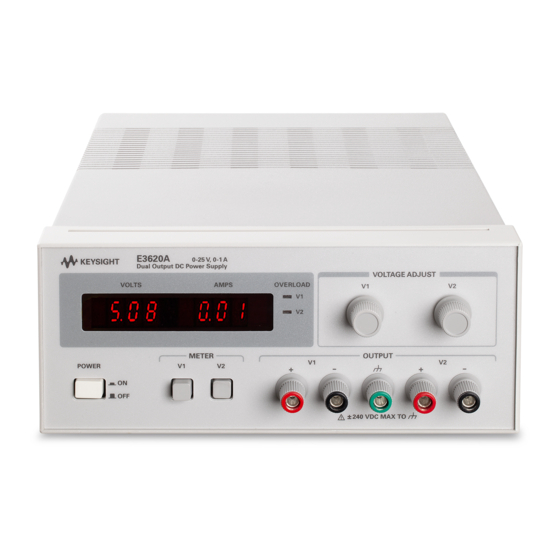
Requirements ICES/NMB-001 DESCRIPTION This ISM device complies with Canadian ICES-001. The Model E3620A Dual Output Power Supply is a compact, Cet appareil ISM est conforme à la norme NMB-001 du constant voltage/current limiting supply that delivers two iso- Canada. lated 0 to 25 V outputs rated at 1 A. It is an ideal power supply... -
Page 7: Line Fuse
If damage is found, a claim should The instrument is shipped ready for bench operation. Before be filed with the carrier. The Agilent Technologies Sales and applying power to the supply, please read the INPUT Service office should be notified as soon as possible. -
Page 8: Outline Diagram
) set the voltage INTRODUCTION level of the corresponding output. The voltage controls are 10 This section describes the operating controls and indicators, turn potentiometers. turn-on checkout procedures, and other operating consider- ations for the Model E3620A Dual Output Power Supply. -
Page 9: Turn-On Checkout Procedure
Each output control (V1 and V2) must be adjusted in order to obtain the total output voltage. Diodes connected The dual outputs of the E3620A can be used individually, in internally across each output protect the supply's output filter series, or in parallel. -
Page 10: Reverse Current Loading
OUTPUT CAPACITANCE the output current over the preset limit. Although the preset limit may be set higher than the average output current, high An internal capacitor across the output terminals of the supply peak currents (as occur in pulse loading) may exceed the helps to supply high-current pulses of short duration during preset current limit and cause crossover to occur and constant-voltage operation. - Page 11 중 출 력 전 원 공 급 기 A g i l e n t 모 델 E 3 6 2 0 A 용 및 서 비 스 지 침 서 뉴 얼 부 품 번 호 . E 3 6 2 0 - 9 0 0 0 1 0 0 7 년...
- Page 12 전 요 약 기 기 의 운 용 , 서 비 스 및 수 리 시 에 는 아 래 의 일 반 적 인 안 전 수 칙 을 반 드 시 지 켜 야 합 니 다 . 아 래 의 안 전 수 칙 이 나 이 지 침 서 에 포 함 되 어...
- Page 13 차 안 전 요 약 ............. . 2 - 2 일...
-
Page 14: 일 반 정 보
일 반 정 보 기 기 및 지 침 서 확 인 련 릅 련 국 최 종 포 함 " Y " 작 제 품 설 명 국 말 레 첫 작 4 = 4 = 작 머 섯 련... -
Page 15: 설 치
입 력 전 압 퓨 즈 A g i l e n t 부 품 번 호 입 력 퓨 즈 센 옆 래 s l o w b l o w 1 . 사 양 ± ± ± μ ±... -
Page 16: 외 형 도
외 형 도 랙 장 착 입 력 전 원 요 구 사 항 전 원 코 드 ( c a b l e ) 림 2 . 전 면 판 조 정 자 및 표 시 등 조 정 자 입... -
Page 17: 운 용
직 렬 운 용 운 용 과 부 하 보 호 회 로 병 렬 운 용 NOTE V 1 과 V 2 출 력 의 실 제 운 용 중 부 하 가 변 하 여 출 력 전 류 가 전 류 제... -
Page 18: 출 력 캐 피 시 턴 스
하 도 록 더 미 부 하 저 항 을 결 하 는 것 이 필 요 합 니 다 . 츌 력 캐 피 시 턴 스 공 급 기 의 출 력 단 자 에 결 되 어 있 는 내 부 캐 피 시 터 는 정 전 압 운... - Page 19 DC-STROMVERSORGUNG MIT ZWEI AUSGÄNGEN Agilent E3620A BEDIENUNGS- UND SERVICE-HANDBUCH Handbuch Teilenummer E3620-90001 Oktober 2007 7. Ausgabe...
- Page 20 Die nachstehenden allgemeinen Sicherheitsrichtlinien müssen bei der Bedienung, Wartung oder Reparatur des Gerätes unbedingt beachtet werden. Das Nichtbeachten der Richtlinien oder besonderer Warnungen an anderen Stellen dieses Handbuchs verstößt gegen Sicherheitsstandards, Herstellervorschriften und vorgesehene Betriebsweise des Geräts. Agilent Technologies übernimmt keine Verantwortung für Schäden, die durch Nichtbeachten dieser Richtlinien entstehen.
- Page 21 Inhaltsverzeichnis SICHERHEITSHINWEISE ............3-2 ALLGEMEINE INFORMATIONEN .
-
Page 22: Sicherheitshinweise
IEC 801-2(1991): Electrostatic Discharge Requirements IEC 801-3(1984): Radiated Electromagnetic Field BESCHREIBUNG Requirements Das Modell Agilent E3620A ist eine kompakte DC-Stromver- IEC 801-4(1988): Electrical Fast Transient/Burst sorgung mit zwei voneinander unabhängigen Ausgängen, die Requirements jeweils eine Spannung bis zu 25 V und einen Strom bis zu 1 A liefern können. -
Page 23: Netzsicherung
Spediteur. Benachrichtigen Sie außer- Das Gerät wird in einem einsatzbereiten Zustand ausgelie- dem umgehend das nächstgelegene Vertriebs- und Ser- fert. Lesen Sie bitte vor dem Anschluss des Gerätes an das vice-Zentrum von Agilent Technologies. Stromnetz den Abschnitt “NETZANSCHLUSS”. Mechanische Überprüfung Aufstellung und Kühlung Kontrollieren Sie, ob die Drehknöpfe und Anschlüsse in Ord-... -
Page 24: Maßskizze
Die beiden Einsteller V1 und V2 ( ) dienen zum Ein- Dieser Abschnitt beschreibt die Bedienungselemente und An- stellen der Ausgangsspannung. Es handelt sich zeigen der Stromversorgung Agilent E3620A sowie eine ein- 10-Gang-Potentiometer. fache Funktionsprüfung und die Bedienung des Gerätes. -
Page 25: Funktionsprüfung
Stromversorgung verbunden wer- den; das andere Ende der Abschirmung sollte frei bleiben. BEDIENUNG Die beiden Ausgänge der Stromversorgung Agilent E3620A Wenn aus irgendwelchen Gründen externe Verteilerklemmen können voneinander unabhängig benutzt oder in Serie oder verwendet werden müssen, verbinden Sie diese über ver- parallel geschaltet werden. -
Page 26: Parallelschaltung
Parallelschaltung Zur Vergrößerung des maximalen Ausgangsstroms können Stromver- Aktive die beiden Ausgänge (V1 und V2) parallelgeschaltet werden. sorgung Last Der Gesamt-Ausgangsstrom ist gleich der Summe der Aus- gangsströme der einzelnen Stromversorgungen. Die Aus- gangsspannung einer der Stromversorgungen sollte auf die gewünschte Spannung eingestellt werden und die der übri- gen auf einen geringfügig höheren Wert. - Page 27 ALIMENTATION A SORTIE DOUBLE Agilent MODELE E3620A GUIDE D’UTILISATION ET DE MAINTENANCE Octobre 2007 N° de référence du guide E3620-90001 Edition 7...
- Page 28 Le non-respect de ces précautions ou des autres avertissements mentionnés dans ce guide va à l’encontre des normes de sécu- rité relatives à la conception, à la fabrication ou à l’usage prévu de cet instrument. Agilent Technologies ne peut être tenu responsable des défaillances de l’instrument suite au non-respect de ces conditions par le client.
- Page 29 Table des Matières CONSIGNES DE SECURITE ............4-1 INFORMATIONS GENERALES .
-
Page 30: Informations Generales
IEC 801-2(1991): Exigences en matière d’Immunité aux DESCRIPTION décharges électrostatiques L’alimentation à sortie double Modèle E3620A est une alimenta- IEC 801-3(1984): Exigences en matière de susceptibilité aux tion compacte à tension constante et à limitation de courant qui rayonnements électromagnétiques délivre deux sorties isolées nominales de 0 à... -
Page 31: Fusible Secteur
L’instrument est livré prêt pour fonctionner sur banc. Avant la son du transporteur. L’agence commerciale et de service mise sous tension de l’alimentation, lisez le paragraphe après-vente Agilent Technologies doit en être avertie au plus CARACTERISTIQUES DE L’ALIMENTATION D’ENTREE. tôt. -
Page 32: Schéma D'encombrement
Les contrôles INTRODUCTION des tensions sont des potentiomètres 10 tours. Cette section décrit les contrôles et les voyants de fonction- nement, les procédures de contrôle de mise en service et d’autres caractéristiques d’utilisation pour l’alimentation à sor- tie double Modèle E3620A. -
Page 33: Procedure De Controle De Mise En Service
Les étapes suivantes décrivent l’utilisation des contrôles de la mentations V1 et V2 sont à rétablissement automatique ; face avant du Modèle E3620A illustrés sur la Figure 2 et ser- c’est-à-dire que, lorsque la surcharge est enlevée ou corri- vent à contrôler brièvement si l’alimentation est opération- gée, la tension de sortie est rétablie automatiquement à... -
Page 34: Caracteristiques De Charge
CAPACITE DE SORTIE L’alimentation réglée à la tension de sortie la plus faible agira comme une source de tension constante, tandis que l’alimenta- Un condensateur interne entre les bornes de sortie de l’ali- tion réglée à la sortie plus élevée agira comme une source de mentation contribue à... - Page 35 ALIMENTATORE A DOPPIA USCITA Agilent modello E3620A MANUALE DI USO E MANUTENZIONE Ottobre 2007 Codice Agilent: E3620-90001 VII edizione...
- Page 36 Agilent Technologies certifica che questo prodotto è conforme alle specifiche pubblicate, al momento della spedizione. Agilent Technologies certifica inoltre che le misure di calibrazione sono state eseguite in conformità agli standard del National Institute of Standards and Technology degli Stati Uniti d’America (ex National Bureau of Standards), nei limiti consentiti dalle attrezzature di calibrazione di detta organizzazione e da quelle di altri membri della International Standards Organization.
- Page 37 La mancata osservanza delle seguenti precauzioni o di avvertenze specifiche riportate in questo manuale costituisce una violazione delle norme di progettazione, produzione ed uso previsto dello strumento. Agilent Technologies non si assume alcuna responsabilità in caso di mancato rispetto da parte del cliente delle presenti norme.
- Page 38 Sommario INFORMAZIONI SULLA SICUREZZA ..........5-2 INFORMAZIONI GENERALI .
-
Page 39: Informazioni Generali
3 1/2" su un rack disponibili nelle relative sezioni del presente manuale. standard da 19" REQUISITI DI SICUREZZA ED EMC Il kit è necessario per il montaggio dell’alimentatore E3620A L’alimentatore è conforme alle seguenti norme di sicurezza e su rack. compatibilità elettromagnetica (EMC):... -
Page 40: Fusibile Di Linea
FUSIBILE DI LINEA Tensione di linea Fusibile Codice Agilent 100/115 V CA 2110-0702 Il fusibile di linea è situato in prossimità dell’attacco della 230 V CA 2110-0457 corrente alternata. Controllarne caratteristiche eventualmente sostituirlo con il fusibile corretto. I seguenti sono fusibili a fusione lenta. Tavola 1. -
Page 41: Schema Generale
I due controlli di tensione V1 e V2 ( ) impostano il informazioni sull’utilizzo dell’alimentatore a doppia uscita livello di tensione dell’uscita corrispondente. I dispositivi di Agilent modello E3620A. controllo sono due potenziometri a dieci giri. -
Page 42: Procedura Di Verifica All'accensione
I punti che seguono descrivono l’uso dei dispositivi di propria potenza di uscita se la tensione è al di sopra del controllo del modello E3620A illustrati nella Figura 2 e proprio valore nominale. La potenza può essere aumentata consentono di svolgere una breve verifica del funzionamento fino al 5% senza che l’alimentatore venga danneggiato, ma... -
Page 43: Carichi
CARICHI CAPACITA’ DI USCITA Un condensatore interno attraverso i terminali di uscita In questa sezione verranno fornite informazioni sui vari tipi di dell’alimentatore aiuta a fornire impulsi di corrente elevata di carichi collegati all’uscita dell’alimentatore. breve durata durante il funzionamento a tensione costante. Qualsiasi capacità... - Page 44 ュ ア ル 出 力 電 源 装 置 Agilent E3620A モ ル 作 お よ び サ ー ビ ス ・ マ ニ ュ ア ル 2007 E3620-90001 ニ ュ ア ル ・ パ ー ツ ・ ナ ン バ...
- Page 45 載 さ れ て い る 注 意 事 項 ま た は 特 別 な 警 告 に 従 わ な い 場 合 は 、 設 計 、 製 造 、 ま た は 装 置 の 用 途 に 関 す る 安 全 基 準 に 違 反 す る こ と に な Agilent Technologies り...
- Page 46 次 ............6-2 安...
-
Page 47: 概 要
装 置 と マ ニ ュ ア ル の 識 別 概 要 説 明 E3620A "MY" 4=1994, 5=1995) オ プ シ ョ ン 0EM, 0E3 AC115 V 10%, 47-63 Hz 0EM: AC 115 V ± 10%, 47-63 Hz 入 力... -
Page 48: イ ン ス ト ー ル
Agilent ラ イ ン ・ ヒ ュ ー ズ 100/115 Vac 2110-0702 230/115 Vac 2110-0457 仕 様 AC 115 V ± 10%, 47-63 Hz, 200 VA, 130 W 0E9: AC 100 V ± 10%, 47-63 Hz, 200 VA, 130 W 0.1%+5mV (20Hz 0E3:... -
Page 49: 外 形 図
ラ イ ン ・ ス イ ッ チ 電 圧 測 定 と 電 流 測 定 • VOLTS/AMPS 図 外 形 図 操 作 の 手 引 き メ モ は じ め に E3620A 電 圧 コ ン ト ロ ー ル... -
Page 50: 電 源 投 入 チ ェ ッ ク ア ウ ト ・ プ ロ シ ジ ャ
電 源 投 入 チ ェ ッ ク ア ウ ト ・ プ ロ シ ジ ャ 定 格 出 力 を 超 え た 稼 動 状 況 E3620A 負 荷 の 接 続 b. V1 ) V1 c. V1 1.0 A + 5%... -
Page 51: 逆 電 流 の ロ ー デ ィ ン グ
出 力 キ ャ パ シ タ ン ス 落 支 援 逆 電 流 の ロ ー デ ィ ン グ 向 働 際 平 均 率 結 逆 電 圧 保 護 抵 抗 極 影 響 耐 久 励... - Page 52 FUENTE DE ALIMENTACIÓN DE SALIDA DOBLE Agilent MODELO E3620A MANUAL DE FUNCIONAMIENTO Y SERVICIO Octubre de 2007 Manual con nº de parte E3620-90001 Edición 7...
- Page 53 Agilent Technologies no se responsabiliza de la falta de cumplimiento de estos requisitos por parte del cliente.
- Page 54 Tabla de contenido RECOMENDACIONES DE SEGURIDAD ..........7-1 INFORMACIÓN GENERAL.
-
Page 55: Recomendaciones De Seguridad
Electroestáticas DESCRIPCIÓN IEC 801-3(1984): Requisitos de Campos El modelo E3620A de fuente de alimentación de doble salida Electromagnéticos Radiados es una fuente compacta con limitación de tensión y corriente constante que suministra dos salidas aisladas de 0 a 25 V a 1 IEC 801-4(1988): Requisitos de Ráfagas/Alteraciones... -
Page 56: Especificaciones
Si se encuentra algún daño, deberá rellenarse párrafo siguiente para comprobar que la fuente está una reclamación dirigida al transportista. Deberá notificar a la operativa. También puede realizar una comprobación más Oficina de Ventas y Servicios de Agilent Technologies tan completa fuente mediante PRUEBA pronto como sea posible. -
Page 57: Datos De Instalación
Este instrumento utiliza aire para enfriarse. Debe dejarse el modelo E3620A de fuente de alimentación de salida doble. suficiente espacio para que el flujo de aire frío pueda alcanzar los laterales y la parte posterior del equipo mientras esté en PRECAUCION funcionamiento. -
Page 58: Controles De Tensión
En los pasos siguientes de explica cómo utilizar los controles Si se producen condiciones de sobrecarga, las fuentes V1 y del panel frontal del Modelo E3620A que aparecen en la V2 protegerán la carga limitando la corriente al valor mínimo Figura 2 y sirven como una comprobación breve para... -
Page 59: Utilización En Paralelo
Utilización en paralelo Las fuentes V1 y V2 pueden conectarse en paralelo para FUENTE DE DISPOSITIVO DE obtener una corriente total de salida mayor que aquella de la ALIMENTACION CARGA ACTIVO que se podría disponer con una sola fuente. La corriente total de salida es la suma de las corrientes de salida de las fuentes por separado. - Page 60 Agilent E3620A 双 输 出 电 源 作 和 维 护 手 册 2007 E3620-90001 册 产 品 号 : 月 第 版...
- Page 61 全 概 要...
- Page 62 录 ............... 8-2 安...
-
Page 63: 一 般 信 息
一 般 信 息 仪 器 和 手 册 标 识 说 明 4=1994 5=1995 E3620A 25 V 选 件 0EM, 0E3 115 Vac ± 10% 47-63 Hz 115 Vac ± 10% 47-63 Hz 230 Vac ± 10% 47-63 Hz 100 Vac ±... -
Page 64: 电 气 检 查
参 数 100/115 Vac 2110-0702 230 Vac 2110-0457 线 路 熔 断 器 参 数 115 Vac ± 10%, 47-63 Hz, 200 VA, 130 W 0.1% 5 mV 20 Hz 100 Vac ± 10%, 47-63 Hz, 200 VA, 130 W 230 Vac ±... -
Page 65: 轮 廓 图
电 压 和 电 流 测 量 VOLTS/ AMPS METER 图 轮 廓 图 电 压 控 制 器 操 作 说 明 加 电 检 验 步 骤 E3620A 简 介 E3620A Service Information Service Information LINE Service Information Line voltage option conversion 缘... -
Page 66: 操 作
屏 蔽 简 略 故 障 再 Service Information 疑 答 串 联 操 作 操 作 串 联 E3620A 串 联 联 50 V 240 V 才 二 管 滤 影 串 联 过 载 保 护 电 路... -
Page 67: 输 出 电 容
输 出 电 容 脉 添 脉 但 会 均 脉 反 向 电 压 保 护 二 管 二 管 串 联 晶 管 横 影 串 联 晶 管 抵 抗 住 二 管 们 联 二 管 间... - Page 68 Agilent E3620A 雙 輸 出 電 源 供 應 器 作 與 檢 修 手 冊 2007 : E3620-90001 冊 編 號 月 第 版...
- Page 69 全 摘 要...
- Page 70 錄 ............... 9-2 安...
-
Page 71: 一 般 資 訊
EN 50082-1(1992) / 一 般 資 訊 IEC 801-2(1991): Electrostatic Discharge Requirements IEC 801-3(1984): Radiated Electromagnetic Field Requirements 說 明 E3620A IEC 801-4(1988): Electrical Fast Transient/Burst Requirements 25 V 針 計 模 擬 板 業 想 單 和 器 與 手 冊 識 別... -
Page 72: 初 始 檢 查
線 路 保 險 絲 線 電 壓 保 險 絲 安 捷 倫 零 件 編 號 100/115 Vac 2110-0702 230 Vac 2110-0457 格 規 格 輸 入 穩 定 性 ( 輸 出 變 化 ) 115 Vac ±10% 47-63 Hz 200 VA 130 W 100 Vac ±10% 47-63 Hz 200 VA 130 W 0.1%... -
Page 73: 概 要 圖 表
操 作 指 示 METER 注 意 兩 個 按 鈕 不 可 同 時 鬆 開 ( 按 鈕 向 外 ) 或 按 下 。 簡 介 壓 控 制 鈕 控 鈕 和 平 E3620A 控 鈕 轉 位... -
Page 74: 開 機 檢 查 程 序
機 檢 查 程 序 每 盡 量 短 扭 捲 屏 蔽 低 雜 E3620A 收 屏 蔽 則 列 步 驟 面 板 控 圖 所 另 否 簡 查 收 Service Information 負 載 備 循 查... -
Page 75: 反 向 電 壓 保 護
輸 出 電 容 跨 容 幫 助 動 式 電 源 負 載 裝 置 供 應 器 期 間 短 期 高 脈 衝 容 促 脈 衝 容 量 但 所 高 脈 衝 平 均 大 運... - Page 76 This section presents the principles of operation for the value determined by the V1 VOLTAGE control of the front E3620A Dual Output Power Supply. Throughout this discus- panel. Any error in the actual output as compared to the sion, refer to both the block diagram of Figure A-1 and the desired output is amplified by an operational amplifier and schematic of Figure A-10 and Figure A-11.
- Page 77 The input ac line voltage is first applied to the preregulator which operates in conjunction with the preregulator control circuit to rectify the tap switched AC voltage. This preregu- lator minimizes the power dissipated in the series regulating elements by controlling the dc level across the input filter capacitors depending on the output voltage.
- Page 78 Table A-1. Test Equipment Required TYPE REQUIRED CHARACTERISTICS RECOMMENDED MODEL Sensitivity : 100 μV Oscilloscope Display transient response and ripple Agilent 54503A Bandwidth : 20 MHz/100 MHz and noise waveforms. RMS Voltmeter True rms, 20 MHz bandwidth Measure rms ripple and noise Sensitivity : 1 mV voltage.
- Page 79 and that the current limit circuits function, proceed as follows: Rated Output Voltage and Voltmeter Accuracy a. With no loads connected: turn on the supply and push the V1 METER switch in. Connect a DVM between the V1 + and - terminals and set V1 VOLTAGE control until front panel voltmeter indicates 17.00 volts.
- Page 80 Load Regulation (Load Effect) RMS Measurement Definition: The immediate change, • , in the static value of dc The rms measurement is not an ideal representation of the output voltage resulting from a change in load resistance from open noise, since fairly high output noise spikes of short duration circuit to the value that yields maximum rated output current (or vice could be present in the ripple and not appreciably increase versa).
- Page 81 c. Connect the DVM across R . Operate the DVM in ac volt- Adjust the oscilloscope to display transients as shown in Figure A-9. age mode. g. Check that the pulse width (t ) of the transients at 15 d. Turn on the supply. e.
- Page 82 TROUBLESHOOTING c. If none of the symptoms of Table A-2 apply, proceed to Table A-3. This table provides an initial troubleshooting Before attempting to troubleshoot the power supply, ensure procedure that also directs you to the more detailed pro- that the fault is with the supply and not with an associated cedures which follow it.
- Page 83 Table A-4. Output Voltage Bias and Reference Voltage Check STEP ACTION RESPONSE NEXT ACTION Check +12V bias. a. Normal (+12V ± 5%) a. Proceed to step (3). b. Voltage high b. Check U13(for V2 output) or U23(for V1 output) for short.
- Page 84 Table A-6. V2 Supply Troubleshooting SYMPTOM STEP - ACTION RESPONSE PROBABLE CAUSE High output voltage 1. Attempt to turn off Q1 by a. Output voltage remains high. a. Q1 shorted. (higher than rating) shorting emitter-to-col- b. Output voltage decreases. b. Remove short and proceed to step lector of Q6.
- Page 85 Table A-8. V2 Preregulator/Control Circuit Troubleshooting (Cont’d) Measure the voltage for pin 14 of U6. a. Low voltage(-12 V). a. U4 defective. b. High voltage(+12 V). b. Proceed to step 7. Measure the voltage for pin 14 of U7. a. High voltage(+12 V). a.
- Page 86 ADJUSTMENT AND CALIBRATION Current Limit Adjustment To adjust the current limit circuit in the V1 or V2 supply, pro- ceed as follows: a. Turn the current limit adjustment pot (R63 for V1 supply or R34 for V2 supply) to fully counter clockwise. b.
- Page 89 (tel) (65) 6375 8100 (fax) (65) 6755 0042 Or visit Agilent worlwide Web at: www.agilent.com/find/assist Product specifications and descriptions in this document are subject to change without notice. © Agilent Technologies, Inc. 2002-2007 Printed in Malaysia Seventh Edition, October 2007 E3620-90001 Agilent Technologies...