Agilent Technologies E3633A Service Manual
Hide thumbs
Also See for E3633A:
- Service manual (136 pages) ,
- User manual (176 pages) ,
- Operating manual (175 pages)
Table of Contents
Advertisement
Quick Links
Service Guide
P a r t N u m b e r : E 3 6 3 4 - 9 0 0 1 0
O c t o b e r 2 0 0 7 .
F o r W a r r a n t y i n f o r m a t i o n , r e f e r t o t h e b a c k o f t h e m a n u a l .
© C o p y r i g h t A g i l e n t T e c h n o l o g i e s , I n c . 1 9 9 8 – 2 0 0 7
A l l R i g h t s R e s e r v e d .
A g i l e n t E 3 6 3 3 A a n d E 3 6 3 4 A
D C P o w e r S u p p l i e s
Agilent Technologies
Advertisement
Table of Contents

Related Manuals for Agilent Technologies E3633A


Summary of Contents for Agilent Technologies E3633A
-
Page 1: Agilent Technologies
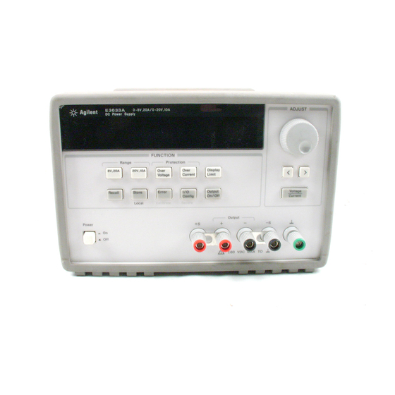
A l l R i g h t s R e s e r v e d . A g i l e n t E 3 6 3 3 A a n d E 3 6 3 4 A D C P o w e r S u p p l i e s Agilent Technologies... - Page 2 T h e A g i l e n t E 3 6 3 3 A a n d A g i l e n t E 3 6 3 4 A a r e h i g h p e r f o r m a n c e 2 0 0 w a t t s i n g l e - o u t p u t d u a l r a n g e p r o g r a m m a b l e D C p o w e r s u p p l i e s w i t h b o t h G P I B a n d R S - 2 3 2 i n t e r f a c e s .
-
Page 3: The Front Panel At A Glance
The Front Panel at a Glance 1 8V/20A range selection key (E3633A) 7 Store operating state/Local key 25V/7A range selection key (E3634A) 8 Error/Calibrate key 2 20V/10A range selection key (E3633A) 9 I/O Configuration/Secure key 50V/4A range selection key (E3634A) - Page 4 ’ ’ k e y w h e n t h e p o w e r s u p p l y i s i n t h e c a l i b r a t i o n m o d e . *For Agilent E3633A Model **For Agilent E3634A Model...
- Page 5 On/Off N o t e All front panel keys and controls can be disabled with remote interface commands. The Agilent E3633A and Agilent E3634A must be in "Local" mode for the front panel keys and controls to function.
-
Page 6: Display Annunciators
Power supply is addressed to listen or talk over a remote interface. Power supply is in remote interface mode. Shows the 8V/20A range is selected. (Agilent E3633A model) Shows the 20V/10A range is selected. (Agilent E3633A model) Shows the 25V/7A range is selected. (Agilent E3634A model) Shows the 50V/4A range is selected. - Page 7 The Rear Panel at a Glance 1 Power-line voltage setting 5 GPIB (IEEE-488) interface connector 2 Power-line fuse-holder assembly 6 RS-232 interface connector 3 AC inlet 7 Rear output terminals 4 Power-line module Use the front-panel key to: Config • Select the GPIB or RS-232 interface (see chapter 3 in User’s Guide). •...
- Page 8 1-800-829-4444 in the United States, or contact your nearest Agilent Technologies Sales Office. If your Agilent E3633A or Agilent E3634A fails within n e year of purchase, Agilent will repair or replace it free of charge. Call 1-800-258-5165 ("Express Exchange") in the United States, or contact your nearest Agilent Technologies...
-
Page 10: Table Of Contents
Contents C h a p t e r 1 S p e c i f i c a t i o n s P e r f o r m a n c e S p e c i f i c a t i o n s - - - - - - - - - - - - - - - - - - - - - - - - - - - - - 1 1 S u p p l e m e n t a l C h a r a c t e r i s t i c s - - - - - - - - - - - - - - - - - - - - - - - - - - - 1 3 C h a p t e r 2 Q u i c k S t a r t T o P r e p a r e t h e P o w e r S u p p l y f o r U s e - - - - - - - - - - - - - - - - - - - - - 2 3... - Page 11 Contents C h a p t e r 3 C a l i b r a t i o n P r o c e d u r e s ( C o n t i n u e d ) C o n s t a n t V o l t a g e ( C V ) V e r i f i c a t i o n s - - - - - - - - - - - - - - - - - - - - - - - 5 1 C o n s t a n t V o l t a g e T e s t S e t u p - - - - - - - - - - - - - - - - - - - - - - - - - - 5 1 V o l t a g e P r o g r a m m i n g a n d R e a d b a c k A c c u r a c y - - - - - - - - - - - 5 1...
- Page 12 Contents C h a p t e r 5 S e r v i c e O p e r a t i n g C h e c k l i s t - - - - - - - - - - - - - - - - - - - - - - - - - - - - - - - - - - - 9 7 I s t h e P o w e r S u p p l y I n o p e r a t i v e ? - - - - - - - - - - - - - - - - - - - - - - 9 7 D o e s t h e P o w e r S u p p l y F a i l S e l f - T e s t ? - - - - - - - - - - - - - - - - - - 9 7 T y p e s o f S e r v i c e A v a i l a b l e - - - - - - - - - - - - - - - - - - - - - - - - - - - - - - 9 8...
- Page 13 Contents...
- Page 14 Specifications...
-
Page 15: Specifications
Specifications T h e p e r f o r m a n c e s p e c i f i c a t i o n s a r e l i s t e d i n t h e f o l l o w i n g p a g e s . S p e c i f i c a t i o n s a r e w a r r a n t e d i n t h e t e m p e r a t u r e r a n g e o f 0 t o 4 0 °... -
Page 16: Chapter 1 Specifications
Chapter 1 Specifications Performance Specifications Performance Specifications Table 1-1. Performance Specifications Parameter Agilent E3633A Agilent E3634A Output Ratings Low Range 0 to +8 V/0 to 20 A 0 to +25 V/0 to 7 A (@ 0 °C - 40 °C) - Page 17 Chapter 1 Specifications Performance Specifications Transient Response Time μ L e s s t h a n 5 0 s e c f o r o u t p u t t o r e c o v e r t o w i t h i n 1 5 m V f o l l o w i n g a c h a n g e i n o u t p u t c u r r e n t f r o m f u l l l o a d t o h a l f l o a d o r v i c e v e r s a Command Processing Time A v e r a g e t i m e f o r o u t p u t v o l t a g e t o b e g i n t o c h a n g e a f t e r r e c e i p t o f d i g i t a l d a t a...
-
Page 18: S U P P L E M E N T A L C H A R A C T E R I S T I C
Chapter 1 Specifications Supplemental Characteristics Supplemental Characteristics Table 1-2. Supplemental Characteristics Parameter Agilent E3633A Agilent E3634A Output Programming Range Low Range 0 to +8.24 V/ 0 to +25.75 V/ (maximum programmable values) 0 to 20.6 A 0 to 7.21 A High Range 0 to +20.6 V/... -
Page 19: Operating Temperature
Chapter 1 Specifications Supplemental Characteristics Output Voltage Overshoot D u r i n g t u r n - o n o r t u r n - o f f o f a c p o w e r , o u t p u t p l u s o v e r s h o o t w i l l n o t e x c e e d 1 V i f t h e o u t p u t c o n t r o l i s s e t t o l e s s t h a n 1 V . -
Page 20: Storage Temperature
N e t 9 . 5 k g ( 2 1 l b ) S h i p p i n g 1 2 k g ( 2 6 l b ) Figure 8-1. Dimensions of Agilent E3633A and E3634A Power Supplies... - Page 21 Chapter 1 Specifications Supplemental Characteristics...
- Page 22 Quick Start...
-
Page 23: Quick Start
A n n u n c i a t o r s ’ ’ o n p a g e 5 f o r m o r e i n f o r m a t i o n . *For Agilent E3633A Model **For Agilent E3634A Model... -
Page 24: Chapter 2 Quick Start
‘ ‘ M e t e r m o d e ’ ’ m e a n s t h a t t h e d i s p l a y s h o w s t h e a c t u a l o u t p u t v o l t a g e a n d c u r r e n t . *For Agilent E3633A Model **For Agilent E3634A Model... - Page 25 Chapter 2 Quick Start To Prepare the Power Supply for Use Install the correct line fuse. Remove Remove the power cord. Remove the the power-line voltage selector from the fuse-holder assembly with a flat-blade power-line module. screwdriver from the rear panel. 100 or 115 Vac, 6.3 AT fuse 230 Vac, 3.15 AT fuse Rotate the power-line voltage selector...
-
Page 26: T O C H E C K T H E R A T E D V O L T A G E S O F T H E P O W E R S U P P L
*For Agilent E3633A Model **For Agilent E3634A Model... -
Page 27: T O C H E C K T H E R A T E D C U R R E N T S O F T H E P O W E R S U P P L
( a c t u a l l y , t h e v o l t m e t e r w i l l s h o w t h e v o l t a g e d r o p c a u s e d b y t h e t e s t l e a d ) . *For Agilent E3633A Model **For Agilent E3634A Model... - Page 28 . *For Agilent E3633A Model **For Agilent E3634A Model...
-
Page 29: T O U S E T H E P O W E R S U P P L Y I N C O N S T A N T V O L T A G E M O D
Y o u c a n u s e t h e r e s o l u t i o n s e l e c t i o n k e y s t o m o v e t h e f l a s h i n g d i g i t t o t h e r i g h t o r l e f t w h e n s e t t i n g c u r r e n t . *For Agilent E3633A Model **For Agilent E3634A Model... - Page 30 . *For Agilent E3633A Model **For Agilent E3634A Model...
-
Page 31: T O U S E T H E P O W E R S U P P L Y I N C O N S T A N T C U R R E N T M O D
. *For Agilent E3633A Model **For Agilent E3634A Model... - Page 32 . *For Agilent E3633A Model **For Agilent E3634A Model...
-
Page 33: T O S T O R E A N D R E C A L L T H E I N S T R U M E N T S T A T
Chapter 2 Quick Start To Store and Recall the Instrument State To Store and Recall the Instrument State Y o u c a n s t o r e u p t o t h r e e d i f f e r e n t o p e r a t i n g s t a t e s i n n o n - v o l a t i l e m e m o r y . - Page 34 Chapter 2 Quick Start To Store and Recall the Instrument State Store 4 S a v e t h e o p e r a t i n g s t a t e . T h e o p e r a t i n g s t a t e i s n o w s t o r e d . T o r e c a l l t h e s t o r e d s t a t e , g o t o t h e f o l l o w i n g s t e p s .
-
Page 35: T O P R O G R A M O V E R V O L T A G E P R O T E C T I O
Y o u w i l l s e e t h e a b o v e m e s s a g e a f t e r p r e s s i n g k e y . Voltage *For Agilent E3633A Model **For Agilent E3634A Model... -
Page 36: C H E C K I N G O V P O P E R A T I O
Chapter 2 Quick Start To Program Overvoltage Protection Over Voltage 5 E x i t t h e O V P m e n u . CHANGED T h e “ C H A N G E D ” m e s s a g e i s h i g h l i g h t e d f o r a s e c o n d t o s h o w t h a t t h e n e w O V P t r i p l e v e l i s n o w i n e f f e c t . - Page 37 Chapter 2 Quick Start To Program Overvoltage Protection Over Voltage 3 C l e a r t h e o v e r v o l t a g e c o n d i t i o n a n d e x i t t h i s m e n u . Over N o w , w h e n y o u p r e s s k e y a g a i n , t h e “...
-
Page 38: T O P R O G R A M O V E R C U R R E N T P R O T E C T I O
Y o u w i l l s e e t h e a b o v e m e s s a g e a f t e r p r e s s i n g t h e k e y . Current *For Agilent E3633A Model **For Agilent E3634A Model... -
Page 39: C H E C K I N G O C P O P E R A T I O
Chapter 2 Quick Start To Program Overcurrent Protection Over Current 5 E x i t t h e O C P m e n u . CHANGED T h e “ C H A N G E D ” m e s s a g e i s d i s p l a y e d f o r a s e c o n d t o s h o w t h a t t h e n e w O C P t r i p l e v e l i s n o w i n e f f e c t . - Page 40 Chapter 2 Quick Start To Program Overcurrent Protection Over Current 3 C l e a r t h e o v e r c u r r e n t c o n d i t i o n a n d e x i t t h i s m e n u . Over N o w , w h e n y o u p r e s s k e y a g a i n , t h e “...
-
Page 41: T O R A C K M O U N T T H E P O W E R S U P P L
Chapter 2 Quick Start To Rack Mount the Power Supply To Rack Mount the Power Supply T h e p o w e r s u p p l y c a n b e m o u n t e d i n a s t a n d a r d 1 9 - i n c h r a c k c a b i n e t u s i n g o n e o f t h r e e o p t i o n a l k i t s a v a i l a b l e . - Page 42 Chapter 2 Quick Start To Rack Mount the Power Supply To rack mount two instruments of the same depth side-by-side, order lock-link kit 5061-9694 and flange kit 5063-9214. To install two instruments in a sliding support shelf, order support shelf 5063-9256, and slide kit 1494-0015.
- Page 43 Chapter 2 Quick Start To Rack Mount the Power Supply...
- Page 44 Calibration Procedures...
-
Page 45: Calibration Procedures
Calibration Procedures T h i s c h a p t e r c o n t a i n s p r o c e d u r e s f o r v e r i f i c a t i o n o f t h e p o w e r s u p p l y ’ s p e r f o r m a n c e a n d c a l i b r a t i o n ( a d j u s t m e n t ) . -
Page 46: Chapter 3 Calibration Procedures
Chapter 3 Calibration Procedures Agilent Technologies Calibration Services N o t e If you calibrate the power supply over the remote interface, you must send the *RST command to the power supply or turn the power supply off and on again after performing a calibration to ensure proper power supply operation. -
Page 47: T E S T C O N S I D E R A T I O N
Chapter 3 Calibration Procedures Test Considerations Y o u c a n a l s o e n t e r c a l i b r a t i o n c o n s t a n t s f r o m t h e r e m o t e i n t e r f a c e . R e m o t e o p e r a t i o n i s s i m i l a r t o t h e l o c a l f r o n t - p a n e l p r o c e d u r e . -
Page 48: R E C O M M E N D E D T E S T E Q U I P M E N
Ω Current monitoring (0.01 , 0.1%) ISOTEK Co. Constant current test setup Resistor (Shunt) Model: A-H It is recommended to use a current monitoring resistor after calibration to find the accurate resistance. *For Agilent E3633A Model **For Agilent E3634A Model... -
Page 49: P E R F O R M A N C E V E R I F I C A T I O N T E S T
Chapter 3 Calibration Procedures Performance Verification Tests Performance Verification Tests T h e p e r f o r m a n c e v e r i f i c a t i o n t e s t s u s e t h e p o w e r s u p p l y ’ s s p e c i f i c a t i o n s l i s t e d i n c h a p t e r 1 , ‘... -
Page 50: M E A S U R E M E N T T E C H N I Q U E
Chapter 3 Calibration Procedures Measurement Techniques Measurement Techniques Setup for Most Tests M o s t t e s t s a r e p e r f o r m e d a t t h e f r o n t t e r m i n a l s a s s h o w n i n t h e f o l l o w i n g f i g u r e . -
Page 51: G E N E R A L M E A S U R E M E N T T E C H N I Q U E
Chapter 3 Calibration Procedures Measurement Techniques General Measurement Techniques T o a c h i e v e b e s t r e s u l t s w h e n m e a s u r i n g l o a d r e g u l a t i o n , p e a k t o p e a k v o l t a g e , a n d t r a n s i e n t r e s p o n s e t i m e o f t h e p o w e r s u p p l y , m e a s u r i n g d e v i c e s m u s t b e c o n n e c t e d t h r o u g h t h e h o l e i n t h e n e c k o f t h e b i n d i n g p o s t a t ( A ) w h i l e t h e l o a d r e s i s t o r i s p l u g g e d i n t o t h e f r o n t o f t h e o u t p u t t e r m i n a l s a t ( B ) . -
Page 52: Constant Voltage Test Setup
6 R e c o r d t h e v a l u e d i s p l a y e d o n t h e c o n t r o l l e r . T h i s v a l u e s h o u l d b e w i t h i n t h e l i m i t o f ( D V M ± 5 m V ) . *For Agilent E3633A Model **For Agilent E3634A Model... - Page 53 ( 4 m V ) * o r ( 7 m V ) * * . *For Agilent E3633A Model **For Agilent E3634A Model...
- Page 54 ( 4 m V ) * o r ( 7 m V ) * * . *For Agilent E3633A Model **For Agilent E3634A Model...
- Page 55 0 . 3 5 m V * o r 0 . 5 m V * * . *For Agilent E3633A Model...
-
Page 56: Load Transient Response Time
( t 2 - t 1 ) o f t h e t r a n s i e n t s a t 1 5 m V f r o m t h e b a s e l i n e i s n o m o r e μ t h a n 5 0 s e c f o r t h e o u t p u t . Figure 3-3. Transient Response Time *For Agilent E3633A Model **For Agilent E3634A Model... -
Page 57: Programming
5 R e a d b a c k t h e o u t p u t c u r r e n t o v e r t h e r e m o t e i n t e r f a c e b y s e n d i n g t h e c o m m a n d : MEAS:CURR? *For Agilent E3633A Model **For Agilent E3634A Model... - Page 58 ( 2 . 2 5 m A ) * o r ( 0 . 9 5 m A ) * * . *For Agilent E3633A Model **For Agilent E3634A Model...
-
Page 59: C U R R E N T - M O N I T O R I N G R E S I S T O
. U s e o n l y a r e s i s t i v e l o a d f o r t h i s t e s t . *For Agilent E3633A Model **For Agilent E3634A Model... -
Page 60: Common Mode Current Noise
) . N o t e t h a t t h e c u r r e n t i s l e s s t h a n 1 . 5 *For Agilent E3633A Model **For Agilent E3634A Model... -
Page 61: C V P E R F O R M A N C E T E S T R E C O R
Chapter 3 Calibration Procedures Performance Test Record for Agilent E3633A and E3634A Performance Test Record for Agilent E3633A and E3634A CV Performance Test Record Specifications Test Description Models Actual Result Upper Limit Lower Limit CV Programming Accuracy @ 0 both +0.0100 V... -
Page 62: C A L I B R A T I O N S E C U R I T Y C O D
, a n d t h e n e n t e r i n g a n e w c o d e . S e e t h e p r o c e d u r e o n p a g e 6 3 . *For Agilent E3633A Model **For Agilent E3634A Model... -
Page 63: T O U N S E C U R E T H E P O W E R S U P P L Y F O R C A L I B R A T I O
. *For Agilent E3633A Model... -
Page 64: T O U N S E C U R E T H E P O W E R S U P P L Y W I T H O U T T H E S E C U R I T Y C O D
Chapter 3 Calibration Procedures Calibration Security Code Config Secure 4 U n s e c u r e t h e p o w e r s u p p l y . UNSECURED Config T h e p o w e r s u p p l y i s u n s e c u r e d w h e n y o u p r e s s ( S e c u r e ) k e y . -
Page 65: C A L I B R A T I O N C O U N
Chapter 3 Calibration Procedures Calibration Count Calibration Count T h e c a l i b r a t i o n c o u n t f e a t u r e p r o v i d e s a n i n d e p e n d e n t ‘ ‘ s e r i a l i z a t i o n ’ ’ o f y o u r c a l i b r a t i o n s . -
Page 66: G E N E R A L C A L I B R A T I O N / A D J U S T M E N T P R O C E D U R
Chapter 3 Calibration Procedures General Calibration/Adjustment Procedure General Calibration/Adjustment Procedure T h e c a l i b r a t i o n p r o c e d u r e s f r o m t h e f r o n t p a n e l a r e d e s c r i b e d i n t h i s s e c t i o n . d i s c o n n e c t F o r v o l t a g e c a l i b r a t i o n , a l l l o a d s f r o m t h e p o w e r s u p p l y a n d... -
Page 67: F R O N T P A N E L V O L T A G E A N D C U R R E N T C A L I B R A T I O
Chapter 3 Calibration Procedures General Calibration/Adjustment Procedure Front Panel Voltage and Current Calibration 1 U n s e c u r e t h e p o w e r s u p p l y . T o c a l i b r a t e t h e v o l t a g e a n d c u r r e n t , y o u m u s t u n s e c u r e t h e p o w e r s u p p l y a c c o r d i n g t o t h e p r o c e d u r e g i v e n o n p a g e 6 2 . - Page 68 Chapter 3 Calibration Procedures General Calibration/Adjustment Procedure 6 R e a d t h e D V M a n d c h a n g e t h e l o w v o l t a g e v a l u e o n t h e d i s p l a y t o m a t c h t h e m e a s u r e d v o l t a g e .
- Page 69 Chapter 3 Calibration Procedures General Calibration/Adjustment Procedure 1 0 R e a d t h e D V M a n d c h a n g e t h e h i g h v o l t a g e v a l u e o n t h e d i s p l a y t o m a t c h t h e m e a s u r e d v o l t a g e .
- Page 70 Chapter 3 Calibration Procedures General Calibration/Adjustment Procedure I f t h e c a l i b r a t i o n f a i l s , a ‘ ‘ O V P C A L F A I L ’ ’ m e s s a g e a p p e a r s f o r o n e s e c o n d a n d t h e d i s p l a y s h o w s t h e ‘...
- Page 71 Chapter 3 Calibration Procedures General Calibration/Adjustment Procedure Error Calibrate 1 7 P r e s s i n g t h e ‘ ‘ C a l i b r a t e ’ ’ k e y s a v e s t h e c h a n g e a n d s e l e c t s t h e h i g h c u r r e n t c a l i b r a t i o n p o i n t .
-
Page 72: A B O R T I N G A C A L I B R A T I O N I N P R O G R E S
Chapter 3 Calibration Procedures Aborting a Calibration in Progress Error Calibrate 2 0 P r e s s i n g t h e ‘ ‘ C a l i b r a t e ’ ’ k e y s a v e s t h e n e w O C P c a l i b r a t i o n c o n s t a n t s a n d r e t u r n t o t h e c a l i b r a t i o n m o d e . -
Page 73: Calibration Record For Agilent E3633A/E3634A
Chapter 3 Calibration Procedures Calibration Record for Agilent E3633A/E3634A Calibration Record for Agilent E3633A/E3634A Measurement Supply Being Step Calibration Description Mode (DVM) Adjusted Unsecure the power supply (see page 62). Turn on ‘‘CAL MODE’’ (hold down ‘‘Calibrate’’ and ‘‘Power’’ keys as you turn on the power supply until you hear a long beeps). -
Page 74: C A L I B R A T I O N R E C O R D F O R A G I L E N T E 3 6 3 3 A
Chapter 3 Calibration Procedures Error Messages Error Messages T h e f o l l o w i n g t a b l e s a r e a b b r e v i a t e d l i s t s o f e r r o r m e s s a g e s f o r t h e E 3 6 3 3 A a n d E 3 6 3 4 A . - Page 75 Chapter 3 Calibration Procedures Error Messages C a l i b r a t i o n E r r o r M e s s a g e s Error Error Messages Cal security disabled by jumper Cal secured Invalid secure code Secure code too long Cal aborted...
-
Page 76: A N E X A M P L E P R O G R A M O F E X C E L 9 7 F O R C A L I B R A T I O
'This program was written on a PC with Excel Macros (Visual Basic for Applications) 'for Windows 95 or Windows NT 4.0. It will make software adjustments to the E3633A 'Power Supply on the GPIB bus using a Agilent 34401A Digital Multimeter and a current 'shunt. - Page 77 Exit Sub End If OVPandOCPCalibration True UserAnswer = MsgBox("Connect the Current shunt to the DMM input to measure a current. Connect the output to the shunt.", vbYesNo + vbQuestion, "E3633A Calibration") If UserAnswer = vbNo Then ClosePort Exit Sub End If ActiveCell.Value = "Begin Current Calibration"...
- Page 78 Chapter 3 Calibration Procedures An Example program of Excel 97 for Calibration ActiveCell.Value = "End Middle Current Calibration" StartCalibration CurrentMax, False, shunt 'Set output to maximum current cal ActiveCell.Value = "End Maximum Current Calibration" OVPandOCPCalibration False Message = SendSCPI(power, "Syst:Err?") If InStr(Message, "0") Then ActiveCell.Value = "Current Calibration Complete"...
- Page 79 Chapter 3 Calibration Procedures An Example program of Excel 97 for Calibration Private Function InitializeDevice() SendSCPI power, "*Cls" SendSCPI DMM, "*Rst" 'Set power-on condition for DMM SendSCPI power, "*Rst" 'Set power-on condition for power supply End Function Private Function CheckError(Error As Long, Message As String) As Boolean If Error <...
- Page 80 Chapter 3 Calibration Procedures An Example program of Excel 97 for Calibration Error = viWrite(device, ByVal commandString, Len(commandString), actual) If InStr(commandString, "?") Then Error = viRead(device, ByVal ReadBuffer, 512, actual) ReturnString = ReadBuffer crlfpos = InStr(ReturnString, Chr$(0)) If crlfpos Then ReturnString = Left(ReturnString, crlfpos - 2) End If SendSCPI = ReturnString...
- Page 81 Chapter 3 Calibration Procedures An Example program of Excel 97 for Calibration Private Function DacErrorCorrection() As Boolean Dim Message As String SendSCPI power, "Output On" 'Turn on the power supply output SendSCPI power, "Cal:Dac:Error" For I = 1 To 27 delay 1 ActiveCell.Value = "Waitting for "...
- Page 82 Chapter 3 Calibration Procedures An Example program of Excel 97 for Calibration If bVolt Then 'Send the measured voltage value to the power supply SendSCPI power, "Cal:Volt:Data " & Str(DMMdata) Else 'Send the measured current value to the power supply SendSCPI power, "Cal:Curr:Data "...
- Page 83 Chapter 3 Calibration Procedures An Example program of Excel 97 for Calibration Declaration for Windows 95/NT 4.0 Declare Function viOpenDefaultRM Lib "visa32.dll" (instrumentHandle As Long) As Long Declare Function viOpen Lib "visa32.dll" (ByVal instrumentHandle As Long, _ ByVal viDesc As String, ByVal mode As Long, ByVal timeout As Long, _ vi As Long) As Long Declare Function viClose Lib "visa32.dll"...
- Page 84 Theory of Operation...
-
Page 85: Theory Of Operation
Theory of Operation T h i s c h a p t e r p r o v i d e s b l o c k d i a g r a m l e v e l d e s c r i p t i o n s o f t h e p o w e r s u p p l y . T h e d e s c r i p t i o n s p r o v i d e a b a s i c u n d e r s t a n d i n g o f c i r c u i t o p e r a t i o n a n d a r e i n t e n d e d a s a n a i d i n t r o u b l e s h o o t i n g . -
Page 86: Chapter 4 Theory Of Operation
Chapter 4 Theory of Operation Block Diagram Overview Block Diagram Overview T h i s d i s c u s s i o n p e r t a i n s t o t h e b l o c k d i a g r a m o n t h e n e x t p a g e . T h e p o w e r s u p p l y ’... - Page 87 Chapter 4 Theory of Operation Block Diagram Overview B l o c k D i a g r a m...
-
Page 88: A C I N P U T A N D B I A S S U P P L I E
Chapter 4 Theory of Operation AC Input and Bias Supplies AC Input and Bias Supplies R e f e r r i n g t o t h e s c h e m a t i c s h o w n o n p a g e s 1 2 9 a n d 1 3 0 , t h e a c m a i n s a r e c o n n e c t e d b y a f u s e d p o w e r m o d u l e . -
Page 89: F L O A T I N G L O G I
Chapter 4 Theory of Operation Floating Logic Floating Logic R e f e r r i n g t o t h e s c h e m a t i c s h o w n o n p a g e 1 3 2 , t h e f l o a t i n g c o m m o n l o g i c c o n t r o l s o p e r a t i o n o f t h e e n t i r e i n s t r u m e n t . - Page 90 Chapter 4 Theory of Operation Floating Logic T h e s e r i a l r e g i s t e r i s u s e d t o s e n d a n d r e c e i v e s e r i a l d a t a b y t e s f r o m t h e m a i n c o n t r o l l e r t o t h e D A C s y s t e m , o r t o c o m m u n i c a t e w i t h t h e f r o n t p a n e l c o n t r o l l e r .
-
Page 91: D - T O - A C O N V E R T E
Chapter 4 Theory of Operation D-to-A Converter D-to-A Converter R e f e r r i n g t o t h e s c h e m a t i c s h o w n o n p a g e 1 3 1 , a l l r e f e r e n c e v o l t a g e s o f p o w e r c i r c u i t s a r e d e r i v e d f r o m t h e i n t e r n a l v o l t a g e r e f e r e n c e o f s y s t e m D A C U 2 2 . -
Page 92: A - T O - D C O N V E R T E
Chapter 4 Theory of Operation A-to-D Converter A-to-D Converter R e f e r r i n g t o t h e s c h e m a t i c s h o w n o n p a g e 1 3 1 , t h e a n a l o g - t o - d i g i t a l c o n v e r t e r ( A D C ) i s u s e d t o c h a n g e d c v o l t a g e s i n t o d i g i t a l i n f o r m a t i o n . -
Page 93: P O W E R M E S H A N D C O N T R O
Chapter 4 Theory of Operation Power Mesh and Control Power Mesh and Control R e f e r t o t h e s c h e m a t i c s s h o w n o n p a g e 1 2 9 . F o r t h e p o w e r m e s h a n d c o n t r o l c i r c u i t , t h e p r e r e g u l a t o r w h i c h i s c o n t r o l l e d b y t h e p h a s e c o n t r o l c i r c u i t s i s a d d e d a h e a d o f t h e s e r i e s p a s s t r a n s i s t o r t o m i n i m i z e t h e p o w e r d i s s i p a t e d a t t h e s e r i e s p a s s t r a n s i s t o r b y c o n t r o l l i n g t h e... - Page 94 Chapter 4 Theory of Operation Power Mesh and Control T w o e r r o r a m p l i f i e r s a r e i n c l u d e d i n a C V / C C s u p p l y , o n e f o r c o n t r o l l i n g o u t p u t v o l t a g e , t h e o t h e r f o r c o n t r o l l i n g o u t p u t c u r r e n t .
-
Page 95: E A R T H - R E F E R E N C E D L O G I
Chapter 4 Theory of Operation Earth-Referenced Logic Earth-Referenced Logic R e f e r r i n g t o t h e s c h e m a t i c s h o w n o n p a g e 1 3 3 , t h e e a r t h r e f e r e n c e d l o g i c c i r c u i t s s c h e m a t i c p r o v i d e s a l l r e a r p a n e l i n p u t / o u t p u t c a p a b i l i t y . - Page 96 Service...
- Page 97 Service T h i s c h a p t e r d i s c u s s e s t h e p r o c e d u r e s i n v o l v e d f o r r e t u r n i n g a f a i l e d p o w e r s u p p l y t o A g i l e n t f o r s e r v i c e o r r e p a i r .
-
Page 98: Chapter 5 Service
Chapter 5 Service Operating Checklist Operating Checklist B e f o r e r e t u r n i n g y o u r p o w e r s u p p l y t o A g i l e n t f o r s e r v i c e o r r e p a i r c h e c k t h e f o l l o w i n g i t e m s : Is the Power Supply Inoperative? V e r i f y t h a t t h e a c p o w e r c o r d i s c o n n e c t e d t o t h e p o w e r s u p p l y . -
Page 99: T Y P E S O F S E R V I C E A V A I L A B L
Chapter 5 Service Types of Service Available Types of Service Available I f y o u r p o w e r s u p p l y f a i l s w i t h i n o n e y e a r o f o r i g i n a l p u r c h a s e , A g i l e n t T e c h n o l i g e s I n c . -
Page 100: R E P A C K I N G F O R S H I P M E N
Chapter 5 Service Repacking for Shipment Repacking for Shipment F o r t h e E x p r e s s E x c h a n g e S e r v i c e d e s c r i b e d o n t h e p r e v i o u s p a g e , r e t u r n y o u r f a i l e d A g i l e n t E 3 6 3 3 A o r E 3 6 3 4 A t o t h e d e s i g n a t e d A g i l e n t S e r v i c e C e n t e r u s i n g t h e s h i p p i n g c a r t o n o f t h e e x c h a n g e u n i t . -
Page 101: E L E C T R O S T A T I C D I S C H A R G E ( E S D ) P R E C A U T I O N
Chapter 5 Service Electrostatic Discharge (ESD) Precautions Electrostatic Discharge (ESD) Precautions A l m o s t a l l e l e c t r i c a l c o m p o n e n t s c a n b e d a m a g e d b y e l e c t r o s t a t i c d i s c h a r g e ( E S D ) d u r i n g h a n d l i n g . -
Page 102: T O D I S C O N N E C T T H E O U T P U T U S I N G A N E X T E R N A L R E L A
Chapter 5 Service To Disconnect the Output Using an External Relay To Disconnect the Output Using an External Relay W h e n t h e o u t p u t o f t h e p o w e r s u p p l y i s t u r n e d o f f , i t i s i m p l e m e n t e d b y s e t t i n g t h e o u t p u t t o 0 v o l t s a n d 0 . -
Page 103: T R O U B L E S H O O T I N G H I N T
Chapter 5 Service Troubleshooting Hints Troubleshooting Hints T h i s s e c t i o n p r o v i d e s a b r i e f c h e c k l i s t o f c o m m o n f a i l u r e s . B e f o r e t r o u b l e s h o o t i n g o r r e p a i r i n g t h e p o w e r s u p p l y , m a k e s u r e t h a t t h e f a i l u r e i s i n t h e i n s t r u m e n t r a t h e r t h a n a n y e x t e r n a l c o n n e c t i o n s . -
Page 104: B I A S S U P P L I E S P R O B L E M
Chapter 5 Service Troubleshooting Hints Bias Supplies Problems C h e c k t h a t t h e i n p u t t o t h e v o l t a g e r e g u l a t o r s o f t h e b i a s s u p p l i e s i s a t l e a s t 1 V g r e a t e r t h a n t h e i r o u t p u t . -
Page 105: F R O N T P A N E
Chapter 5 Service Self-Test Procedures Self-Test Procedures Power-On Self-Test E a c h t i m e t h e p o w e r s u p p l y i s p o w e r e d o n , a s e t o f s e l f - t e s t s a r e p e r f o r m e d . T h e s e t e s t s c h e c k t h a t t h e m i n i m u m s e t o f l o g i c a n d m e a s u r e m e n t h a r d w a r e a r e f u n c t i o n i n g p r o p e r l y . - Page 106 Chapter 5 Service Self-Test Procedures 6 0 6 R u n d o w n g a i n o u t o f r a n g e T h i s t e s t c h e c k s t h e n o m i n a l g a i n b e t w e e n t h e i n t e g r a t i n g A D C a n d t h e U 1 9 o n - c h i p A D C .
- Page 107 Chapter 5 Service Self-Test Procedures...
- Page 108 Schematics...
- Page 109 Schematics T h i s c h a p t e r c o n t a i n s c o m p o n e n t l o c a t o r d r a w i n g s , s c h e m a t i c s f o r t h e p o w e r s u p p l y .
- Page 112 © W a r r a n t y S e r v i c e E x c l u s i v e R e m e d i e s S a f e t y I n f o r m a t i o n C o p y r i g h t 1 9 9 8 - 2 0 0 7 A g i l e n t T e c h n o l o g i e s...