
Related Manuals for Agilent Technologies E3614A


Summary of Contents for Agilent Technologies E3614A
- Page 1 Agilent E361xA 60W BENCH SERIES DC POWER SUPPLIES OPERATING AND SERVICE MANUAL FOR MODELS: Agilent E3614A Agilent E3615A Agilent E3616A Agilent E3617A Manual Part No. 5959-5310 April 2000 Edition 8...
-
Page 2: Safety Summary
SAFETY SUMMARY... -
Page 3: Table Of Contents
SAFETY SUMMARY ............. . 1-2 GENERAL INFORMATION . -
Page 4: General Information
One additional manual ACCESSORY The accessory listed below may be ordered from your local Agilent Technologies Sales Office either with the power sup- ply or separately. (Refer to the list at the rear of the manual for address.) Agilent Part No. Description 5063-9240 Rack Kit for mounting one or two 3 1/2"... -
Page 5: Specifications
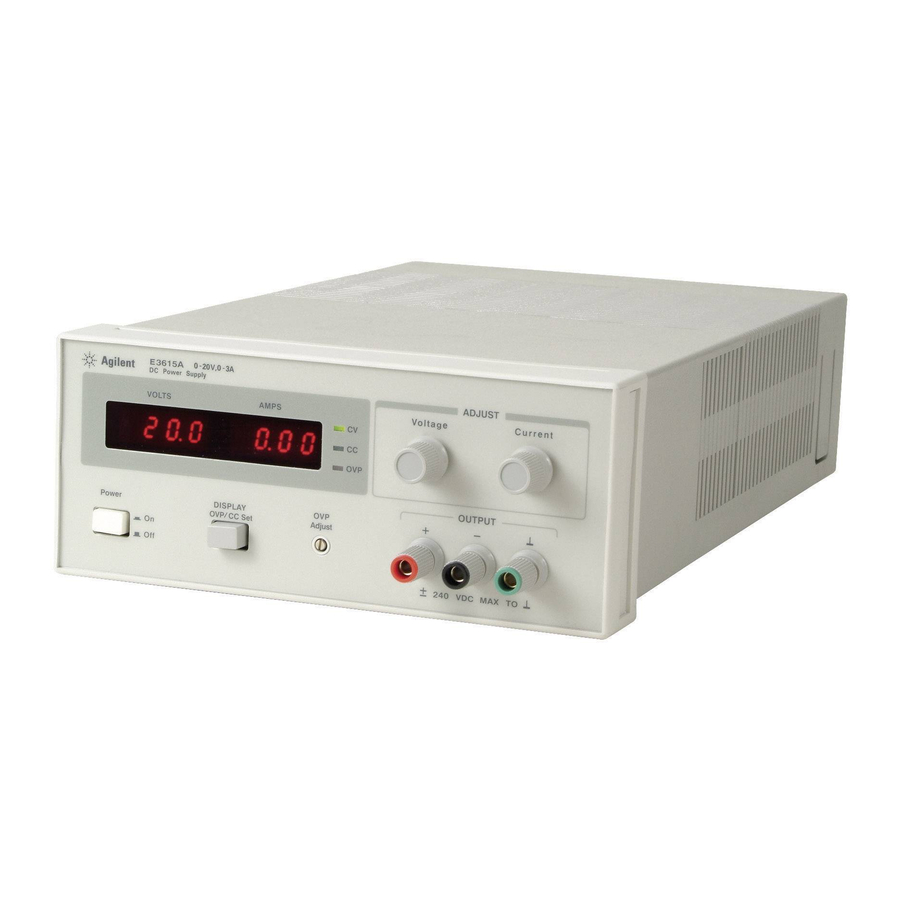
Voltage and current can be programmed via front panel control or remote analog control over the following ranges; E3614A: 0 - 8 V, 0 - 6 A E3615A: 0 - 20 V, 0 - 3 A E3616A: 0 - 35 V, 0 - 1.7 A... -
Page 6: Installation
Save all packing materials until the inspection is completed. If damage is found, a claim should be filed with the carrier. The Agilent Technologies Sales and Service office should be notified. Mechanical Check... -
Page 7: Power Cord
While pressing OVP/CC SET switch, verify that the OVP shutdown is set above 8.0, 20.0, 35.0, or 60.0 Vdc for E3614A, E3615A, E3616A, or E3617A respectively. If not, turn up OVP Adjust with a small flat-blade screwdriver. g. Turn VOLTAGE control fully counter clockwise to ensure that... -
Page 8: Operating Modes
that the current limit value can be set from zero to maximum rated value. OPERATING MODES The setting of the rear panel switch determines the operating modes of the power supply. The local operating mode is set so the power supply senses the output voltage directly at the output terminals (local sensing) for operation using the front panel con- trols (local programming). -
Page 9: Remote Operating Modes
REMOTE OPERATING MODES Remote operating modes discussed below are remote voltage sensing and remote voltage programming. You can set up the unit for remote operating modes by changing the settings of the rear panel switch and connecting the leads from the rear panel termi- nals to the load or the external voltage. -
Page 10: Multiple-Supply Operation
A 1 Vdc change in the remote programming voltage produces a change in output voltage (volt- age gain) as follows: E3614A: 0.8 Vdc, E3615A: 2 Vdc, E3616A: 3.5 Vdc, E3617A: 6 Vdc MASTER... -
Page 11: Normal Series Operation
Setting Voltage and Current. Turn the slave unit's CURRENT control fully clockwise. Adjust the master unit's controls to set the desired output voltage and current. The master supply operates in a completely normal fashion and may be set up for either con- stant voltage or constant current operation as required. -
Page 12: Auto-Series Operation
AUTO-SERIES OPERATION Auto-series operation permits equal or proportional voltage sharing, and allows control of output voltage from one master unit. The voltage of the slaves is determined by the setting of the front panel VOLTAGE control on the master and voltage divider resistor. -
Page 13: Auto-Tracking Operaton
Remote Sensing. To remote sense with auto-series operation, set SENSE switch of the master unit and set SENSE switch of the slave unit to remote. Remote Analog Voltage Programming. To remote analog pro- gram with auto-series operation, connect program (external) volt- ages to the "CV"... -
Page 14: Load Considerations
LOAD CONSIDERATIONS This section provides information on operating your supply with various types of loads connected to its output. PULSE LOADING The power supply will automatically cross over from constant- voltage to constant current operation in response to an increase (over the preset limit) in the output current. -
Page 15: Service Information
SERVICE INFORMATION Figure A-1. Block Diagram PRINCIPLES OF OPERATION (Block Diagram Overview) - Page 16 series pass transistors. Whenever the output voltage is below the sloping V1 line, the control circuit inhibits four SCRs and the input capacitors charge to a voltage determined by N1. Figure A-2 indicates the windings that are connected as a result of the other voltage decisions.
-
Page 17: Performance Tests
a. Perform turn-on checkout procedure given in page 1-7. b. Perform the CV and CC Load Regulation perfor- mance tests given in the following paragraphs respectively. PERFORMANCE TESTS The following paragraphs provide test procedures for verify- ing the power supply's compliance with the specifications of Table 1. - Page 18 Operate the electronic load in constant current mode and set its current to the full rated value of the power supply (6 A for E3614A, 3 A for E3615A, 1.7 A for E3616A and 1 A for E3617A). b. Turn the supply's power on and turn CURRENT con- trol fully clockwise.
- Page 19 Figure A-5. Load Transient Response Time Waveform PARD(Ripple and Noise) Definition: PARD is the Periodic and Random Deviation of the dc output voltage from its average value, over a specified bandwidth and with all other parameters maintained constant. Constant voltage PARD is measured in the root-mean- square(rms) or peak-to-peak(pp) values over a 20 Hz to 20 MHz bandwidth.
- Page 20 a. Connect the test equipment as shown in Figure A-7. b. Turn the supply's power on and turn CURRENT con- trol fully clockwise. c. Turn up output voltage to the full rated value. Check that the supply's CV indicator remains lighted. Reduce VOLTAGE control if not lighted.
- Page 21 Rs. e. Check that the rms noise current is less than 5 mA rms for E3614A, 2 mA rms for E3615A and 500 A rms for E3616A and E3617A respectively. Figure A-8. CC PARD RMS Measurement Test Setup...
-
Page 22: Troubleshooting
Disconnect Rs from test setup on Figure A-9 and connect DVM across output terminal of the supply. b. Turn on the supply. c. To calibrate voltmeter for E3614A, adjust R16 on the display board until front panel VOLTS display reads exactly DVM value. To calibrate voltmeter for... - Page 23 After the trouble has been isolated to one of the feedback loops, troubleshooting can proceed as described in Tables A- 4, A-5, or A-6. Series Regulating Feedback Loop. When troubleshooting the series regulating loop, it is useful to open the loop since measurements made anywhere within a closed loop may appear abnormal.
- Page 24 SYMPTOM Poor Load Regulation a. Refer to "Measurements Techniques" paragraph. (Constant Voltage) b. Check +10 V reference voltage. c. Ensure that the supply is not going into current limit. Poor Load Regulation a. Check +10 V reference voltage. (Constant Current) b.
- Page 25 Table A-6. Preregulator/Control Circuit Troubleshooting STEP MEASURE Set output voltage to 4.5 V +- 0.5 V for E3614A. Set output voltage to 10 V +- 1 V for E3615A. Set output voltage to 15 V +- 1 V for E3616A.
- Page 26 REPLACEABLE PARTS...
- Page 27 Table A-10. Replaceable Parts List...
- Page 28 Table A-10. Replaceable Parts List (Cont'd)
- Page 29 Table A-10. Replaceable Parts List (Cont'd)
- Page 30 Table A-10. Replaceable Parts List (Cont'd)
- Page 31 Table A-10. Replaceable Parts List (Cont'd)
- Page 32 Table A-10. Replaceable Parts List (Cont'd)
- Page 33 Table A-11. Component Value A-19...
- Page 38 Manual Supplement What is a manual supplement?
-
Page 39: Constant Voltage Mode
Voltage and Current Programming of the E3614A/15A/16A/ 17A with a Voltage and Current Source Remote analog voltage programming permits control of the regulated output voltage or current by means of a remotely varied voltage or current. The stability of the programming voltages directly affects the stability of the output. - Page 40 Where is the power supply output voltage. is the programming voltage. A is the gain factor and the values of each model are as below. Model E3614A E3515A E3616A E3617A Alternative Voltage Programming Using Resistors Programming Voltage Common to the Plus Output Figure 3 The M/S2 switch must be in the down position.
- Page 41 Programming Voltage Common to the Minus Output Figure 4 The output will always be the same or less than the programming voltage. The M/S2 switch must be in the down position. For best results, place a 0.1 F capacitor in parallel with R2. = (R1 R2) / R2 x V = R2 / R1+R2) x V Where...
-
Page 42: Constant Current Mode
Constant Current Mode The E3614A/15A/16A/17A may be programmed for constant current with an analog voltage or current. Constant current with analog voltage programming can only be achieved with a voltage source that is common with the positive output terminal. Constant Current with Voltage Programming Figure 5 Set the CC switch down the rear panel, and all others up. - Page 43 Where is the power supply output current in amps. is the programming current in amps. A is the gain. Model E3614A E3515A E3616A E3617A Programming currents can be increased by adding a resistor across the CC+ and CC-. A 10 volts drop across R1 represents full scale current of the power supply. When a 1 kohm resistor is added across R1, the programming currents are as follows with the programming current in mA.
- Page 44 Voltage and Current Programming of the E3614A/15A/16A/17A with Resistors Remote programming with resistors permits control of the regulated output or current by means of a remotely varied resistor. The sum of the resistance of external programming resistors (R1 + R2) should be more than 40 kohm. To have more precise output voltage, use a variable resistor more than 40 kohm.
- Page 45 A is the gain factor and the values of each model are as below. is between 10.11 V and 11.40 V. R = (92800 x R1)/(92800 + R1) R1 + R2>> 40 kohm Model E3614A E3515A E3616A E3617A 1-10-7 0.17...
-
Page 47: Declaration Of Conformity
Supplemental Information: May 4, 2002 Date For further information, please contact your local Agilent Technologies sales office, agent or distributor. Authorized EU-representative: Agilent Technologies Deutschland GmbH, Herrenberger Stra e 130, D71034 Böblingen, Germany DECLARATION OF CONFORMITY According to ISO/IEC Guide 22 and CEN/CENELEC EN 45014 Agilent Technologies, Inc.