Advertisement
Quick Links
Download this manual
See also:
User Manual
Powering your
O-Line
™
(For general system preparation, see the O-Line
system preparation - preliminary guidance)
The Martin Experience
All material © 2008. Martin Audio Ltd. Subject to change without notice.
Advertisement

Summary of Contents for Martin Audio O-Line
- Page 1 Powering your O-Line ™ (For general system preparation, see the O-Line system preparation - preliminary guidance) The Martin Experience All material © 2008. Martin Audio Ltd. Subject to change without notice.
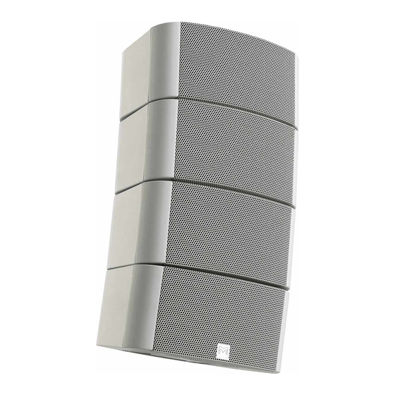
- Page 2 (For general system preparation, see the O-Line preliminary Installation Guide) General Your O-Line is delivered in blocks of 4 modules ready wired in parallel. These four‐module blocks may be separated into smaller blocks or individual modules, linked and paralleled to other blocks or modules using short link wires ‐ or series connected to other blocks or modules using the series Connector pcb supplied with ...
- Page 3 Amplifier choices and limiter settings The following chart shows Martin Audio power amplifier choices (indicated by dots) and Martin Audio DX1.5 or DX2 limiter settings (in red) to obtain optimal performance from the wide range of O-Line array sizes and patch configurations possible. Single channels, two channel and four channel configurations are shown. Multi‐channel configurations are useful where zone control may be required. To avoid amplifier clipping (which dumps excessive power into the HF arrays in the form of odd‐order ...
- Page 4 3 ...
- Page 5 O-Line array patches Single O-Line modules are 16 ohm elements. Four modules are supplied in each carton. These four modules are connected in parallel to form a standard 4 ohm block but may be reconfigured, paralleled or series connected to provide a wide variety of series/parallel configurations chosen from the preceding chart. Please note that if you don’t understand series and parallel electrical configurations, you are strongly advised to enlist the advice of a profession sound system technician or experienced installer. Single channel configurations 1 module array (16 ohms) 2 module array (8 ohms) 4 module array (4 ohms) 4 ...
- Page 6 6 module array (2.67 ohms) 6 module array (10.67 ohms) 5 ...
- Page 7 8 module array (8 ohms) 12 module array (5.3 ohms) 6 ...
- Page 8 16 module array (4 ohms) 7 ...
- Page 9 24 module array (2.67 ohms) 8 ...
- Page 10 Two channel configurations 6 module array (5.34 ohms per channel) 8 module array (4 ohms per channel) 9 ...
- Page 11 12 module array (2.67 ohms per channel) 10 ...
- Page 12 16 module array (8 ohms per channel) 11 ...
- Page 13 24 module array (5.3 ohms per channel) 12 ...
- Page 14 Four channel configurations 16 module array (4 ohms per channel) 13 ...
- Page 15 24 module array (2.67 ohms per channel) 14 ...


