Table of Contents
Advertisement
USER'S
MANUAL
CM-400
Thank you very much for purchasing the CM-500/400/300.
•
To ensure correct and safe usage with a full understanding of
this product's performance, please be sure to read through this
manual completely and store it in a safe location.
•
Unauthorized copying or transferral, in whole or in part, of
this manual is prohibited.
•
The contents of this operation manual and the specifications of
this product are subject to change without notice.
•
The operation manual and the product have been prepared and
tested as much as possible. If you find any misprint or error,
please inform us.
CM-500
CM-300
Advertisement
Table of Contents

Related Manuals for Roland CM-500


Summary of Contents for Roland CM-500
- Page 1 CM-500 MANUAL CM-400 CM-300 Thank you very much for purchasing the CM-500/400/300. • To ensure correct and safe usage with a full understanding of this product's performance, please be sure to read through this manual completely and store it in a safe location.
- Page 2 AVIS Cet appareil numérique de la classe A respecte toutes les exigences du Règlement sur le matériel brouilleur du Canada. ROLAND DG CORPORATION 1-6-4 Shinmiyakoda, Hamamatsu-shi, Shizuoka-ken, JAPAN 431-2103 MODEL NAME : See the MODEL given on the rating plate.
-
Page 3: Table Of Contents
11-2 Error Messages ........................... 42 12 Instruction Support Chart ........................43 13 Character Sets ............................44 Specifications ............................. 45 Windows ® is a registered trademark or trademark of Microsoft ® Corporation in the United States and/or other countries. Copyright © 1998 ROLAND DG CORPORATION... -
Page 4: To Ensure Safe Use
Doing so may result in fire or electrical problem shock. Immediately switch off the power, unplug the power cord from the electrical outlet, and contact your authorized Roland dealer or service center. - Page 5 Do not use with a damaged power Do not attempt to unplug the power cord with wet hands. cord or plug, or with a loose electri- Doing so may cal outlet. result in electrical Use with any other shock. power supply may lead to fire or electrocution.
- Page 6 Use care to avoid pinching the Use the joining screws to secure the fingers when placing the unit on the unit to the stand. stand. Failure to do so may result in Doing so may falling of the unit, result in injury. leading to injury.
-
Page 7: About The Labels Affixed To The Unit
About the Labels Affixed to the Unit These labels are affixed to the body of this product. The following figure describes the location and content of these messages. Do not place hands near the platen while in operation. N'approchez pas vos mains du plateau de travail quand le chariot est en mouvement. - Page 8 - MEMO -...
-
Page 9: Checking Supplied Items
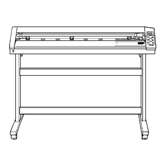
User’s Manual ® for windows Part Names and Functions * The figure shows the CM-500 installed with the PNS-500 special stand. 2-1 Front View Movable Pinch Roller (middle) Front Cover This is used when cutting materials with a width of 762 mm Opening the cover during (30") or more. -
Page 10: Rear View
PAUSE LED SHEET CUT Key This lights up when the CM-500/400/ This is use to sever an already-cut 300 is paused. piece of material from the rolled material. -
Page 11: Setup
Places with excessive electrical noise. Places with excessive humidity or dust. Places with poor ventilation, because the CM-500/400/300 generates considerable heat during operation. Places with excessive vibration. Connect the cable to either the parallel or the serial port. Be sure that the power to both the computer and the main unit is switched off when connecting the cable. -
Page 12: Turning On The Power
Connection Power outlet Power cord Power connector Parallel connector Serial connector (RS-232C) (Centronics) Parallel interface cable (Centyonics) *Parallel interface cable or Serial interface cable Serial interface cable (RS-232C) * Cables are available separately. One which you are sure matches the model of computer being used should be selected. 3-2 Turning on the Power Use the switch at the front-left surface of the unit to turn on the power. -
Page 13: Selecting The Interface
3-3 Selecting the Interface Make sure the settings for the computer (driver) match the settings for the CM-500/400/300 interface. The selected interface type and communication parameters are stored in memory even after the power is switched off. To change the interface type or the communication parameters, configurations must be re-entered. -
Page 14: Basic Operation
Basic Operation 4-1 Installing a Blade Do not touch the tip of the blade with your fingers. Doing so may result in injury, and the cutting performance of the blade will be impaired. NOTICE Be sure to support the tool mounting screw from below when installing the blade holder. Cutting quality may become poor if installed without supporting the screw in this way. -
Page 15: Loading The Material
Failure to do so may result in falling of the roll, leading to injury. Width (horizontal dimension) and maximum cutting width Acceptable material widths Maximum cutting area CM-500 Min.90 mm (3-1/2") Max.1372 mm (54") 1195 mm (47") CM-400 Min.90 mm (3-1/2") Max.1178 mm (46") - Page 16 54" (approx.1372 mm) The right-hand movable pinch roller can be moved within this range. When loading material with a width other than one indicated above, move the right-hand movable pinch roller. CM-500 Material with Material with Material with Material with...
-
Page 17: Loading Roll Material
For information on how to install the sheet hanger, shaft, brake, and stoppers, please refer to the assembly manual for the PNS-500/ 400/300 (the stand for the CM-500/400/300). Mount the shaft at the location on the sheet hanger shown in the figure to match the outer diameter of the rolled material. - Page 18 Position so that the left-hand edge of the material lies over any one of the grit rollers. Move the material from side to side and position so that the right-hand edge of the material lies over the rightmost grit roller. With the material set in place, make sure the grit rollers are positioned correctly.
- Page 19 Close the front cover Close the front cover. Use the keys to select [Roll], then press the key. SELECT SHEET ROLL EDGE PIECE * If cutting is to be performed from the front edge of the material, select "EDGE." PRESS SETUP KEY Press the key.
-
Page 20: To Perform Lengthy Cutting
To Perform Lengthy Cutting NOTICE When performing material feed or cutting, be sure to release the brake. Attempting to perform material feed or cutting with the brake engaged may make normal feed impossible and cause the material to slip. Have on hand a piece of material that's at least 50 mm (2") wider than the cutting width. The chance of the material slipping loose from the pinch rollers can be reduced by braking the shaft and loading the pulled-out material while it's in a tensioned state. -
Page 21: Loading Flat Material (Standard-Size Material, Cut Material, Etc.)
Use the control panel to make the following setting. SELECT SHEET 1 CUT 50cm/s AREA LENGTH ROLL EDGE PIECE 0.250mm 30gf MOVE < 1.0m> Press Press to select the value. Press select [ROLL]. Press to change the value. AREA AXIS Press AREA LENGTH... -
Page 22: About The Cutting Area
The workable area spans the length between the two rollers, minus a margin of about 1 mm (about 0.04") on both sides. If the material length is greater than 1,600 mm (62-15/16") when a flat material (paper) has been loaded, the CM-500/400/300 deter- mines it to be a rolled material and sets the material length to 24,998 mm (984-1/8"). -
Page 23: Cutting Test (How To Adjust Pen Force And Blade Extension)
4-5 Cutting Test (How to Adjust Pen Force and Blade Extension) Before carrying out actual cutting, you may wish to perform a "cutting test" to check whether the unit produces the cutout satisfactorily. This is done by examining the results of the cutting test, and adjusting the blade force and the amount of blade extension. The cutting test should be repeated until the appropriate cutting conditions for the material in use are discovered. -
Page 24: Adjusting The Blade Extension
If the results of steps 1 and 2 show that the cutting quality is not acceptable, refer to "Adjusting the Blade Force" to adjust the blade force. If adjusting the blade force doesn't improve the cutting quality, refer to "Adjusting the Blade Extension" to adjust the blade extension. After adjusting the blade extension, carry out a cutting test and adjust the blade force. - Page 25 Incorrect cutting conditions may cause symptoms such as those described below. Blade force Blade offset • The sheet is easily torn. Corners flare outward, • The cutter requires frequency replacement. with "horns." • Cutting extends through the base paper, and normal advancing of the sheet becomes impossible.
-
Page 26: Downloading Cutting Data
For the interface connection, choose the type of interface you're using to connect the host computer with this product. Select either the parallel (Centronics) or serial (RS-232C) interface. Choose the one that the host computer and the CM-500/400/300 are connected by. -
Page 27: Applying The Completed Cutout
• If you discover after it is stuck in place that air bubbles were trapped under the work, use a needle to puncture them. Then you can smooth out the material out so that it sticks securely. With the CM-500/400/300, the portion where you've performed cutting is automatically cut off from the material. Press the key to cut off the portion from the material. -
Page 28: When Cutting Is Completed
4-8 When Cutting is Completed When not in use for extended periods, unplug the power cord from the electrical outlet. Failure to do so may result in danger of shock, electrocution, or fire due to deterioration of the electrical insulation. NOTICE Do not leave the tool mounting screws tightened. -
Page 29: Maintenance
Maintenance 5-1 Cleaning NOTICE Always turn off the CM-500/400/300 before cleaning it. Never lubricate the mechanisms. Do not clean with solvents (such as benzine or thinners). Cleaning the body Use a cloth moistened with water then wrung well, and wipe gently to clean. Wipe the operation panel and display gently with a clean, soft cloth. -
Page 30: How To Replace The Separating Knife
Doing so may result in injury. If the separating knife, replace it with the replacement blade included with the CM-500/400/300. Follow the steps below to replace the blade. Switch off the power to the CM-500/400/300. -
Page 31: Using The Display Menus
Using the Display Menus This section describes the basic steps for using the display menus. Use this information together with "7 Display Menus Flowchart" on the following page to make menu settings. Use the keys to move the blinking cursor (" ") and choose a setting. Then use the keys to change the value (or the selection) and enable the setting by pressing the key. -
Page 32: Display Menus Flowchart
Power on + Power on + Power on MENU Openning message DEMO CUT CM-500 ENGLISH JAPANESE GERMAN FRENCH Roland DG Corp. ENGLISH/JAPANESE/ After loading a sheet, to select. GERMAN/FRENCH/ close the front cover. Press ENTER to enable the setting. SPANISH/ITALIAN... - Page 33 AREA AXIS BASEPOINT->ENTER ALIGNPOINT->ENTER CROPMARK SETTING CROP-MARK REPLOT SUBMENU COMPLETED! CROPMARK SETTING FAILED,SET AGAIN SUBMENU Pressing moves the blade up or down. CROPMARK UPDOWN ENTER UP/DOWN ->ENTER UPDOWN Pressing , or moves the cutter in OVER-CUT CALIB MOVE ->CURSOR the +Y, -Y, -X, or +X directions, respectively. OVER CUT OVER CUT OFF <ON>...
-
Page 34: Display Menu Lists
Display Menu Lists This chart lists the menus of the CM-500/400/300 grouped by usage. Menus indicated by an Circle (" ") are explained further in the section at the end of the chart. Please refer to these additional explanations when using such menus. - Page 35 Selecting the connection interface INTERFACE This selects the interface for connecting a computer to the CM-500/400/300. Set AUTO this to “PARALLEL” for a parallel connection or to “SERIAL” for a serial connection.
- Page 36 Other setting ENGLISH, JAPA- ENGLISH The CM-500/400/300 is capable of displaying all its menus in either of six languages, English, French, German, Spanish, Italian and Japanese. NESE, GERMAN, FRENCH, SPAN- ISH, ITALIAN...
- Page 37 3 CROPMARK This is used when cutting around pre-printed graphics on a material, such as when making stickers or seals. With the CM-500/400/300, a material is always loaded parallel to the unit. This means that unless the graphics to be cut have been printed parallel to the material, the cutting lines become shifted from the graphics, and it becomes impossible to accurately cut around the graphics (see Figure A below).
- Page 38 • Crop marks cannot be set when the "ROTATE" display menu is set to "90 deg." Load the material (with pre-printed graphics) and install the water based fiber tipped pen included with the CM-500/400/300. The alignment tool is installed in the same way as the blade holder.
-
Page 39: About The Blades And Materials
About the Blades and Materials This section indicates the proper cutting conditions for various types of materials, as well as blade lifespans. Cutting conditions and blade life vary according to the hardness of the material and the usage environment. Making the settings for the conditions described below does not automatically guarantee attractive cutting results in all situations. -
Page 40: Plotting On Paper Media
6. Setting for pen change instructions If CAD software for plotting use has been used to output data (in RD-GL I format), pen-change instructions are sent to the CM-500/ 400/300. If the pen is to be changed during plotting, use "1. Tool number" to set the tool numbers to be used to match the pen numbers set with the software. -
Page 41: What To Do If
11-1 What to do if... CM-500/400/300 troubleshooting Is the power cord connected correctly? Connect the power cord included with the CM-500/400/300 to the unit, and plug the other end securely into an electrical outlet (see “3-1 Setting Up and Connec- tion”). - Page 42 Load a material and press any key to cancel the error message. Shows motor error status. Motor Error This is displayed when the CM-500/400/300 is heavily loaded, such as during a Power ON Again media jam, when heavy stock is cut across a long distance without initial material feed, or when the material is abruptly pulled from the roll during cutting.
- Page 43 Make sure that the left and right edges of the material do not touch the inner position? surfaces, front cover of the CM-500/400/300 during cutting. Such contact may not only damage the material, but could also make normal material advancing impossible and cause the material to slip.
-
Page 44: Error Messages
Baud Rate, Parity, Stop Bits, or Data Parity Error Bits. The protocol settings for the CM-500/400/300 must be made correctly in order to match the settings your computer is set to use.) Appears if the I/O buffer has overflowed.(There is a problem with the connecting cable, or... -
Page 45: Instruction Support Chart
A "CAMM-GL III Programmer's Manual" is available for separate purchase for those wishing to create their own programs for this machine. For further information, please contact your authorized Roland dealer or service center. The list uses marks, each of which means:... -
Page 46: Character Sets
Character Sets Automatic backspace... -
Page 47: Specifications
0.1 mm or less (excluding stretching/contraction of the material) Range for assured repetition accuracy (*) For materials with a width exceeding 610 mm (24"): Length 4,000 mm (157-7/16") (CM-500/400 only) For materials with a width of 610 mm (24") or less : Length 8,000 mm (315-15/16") - Page 48 The following conditions must be satisfied: - Material type: 3M Scotchcal Mastercut Film, ARLON Series 2100 - Special stand (a roll material must be set at the rear and on the inner sheet hanger) - Side margins: 25 mm (1") or more for both the left and right margins - Front margin: 25 mm (1") or more (After loading the material, using the display menu to select “EDGE”...
- Page 49 Interface specifications Parallel Standard In compliance with the specifications of Centronics Input signals STROBE (1 BIT), DATA (8 BITS) Output signals BUSY (1 BIT), ACK (1 BIT) Level of input/output signals TTL level Transmission method Asynchronous S e r i a l Standard RS-232C specifications Transmission method...
- Page 50 The enclosed Roland product is a single user version.