Baroness LM2400 Owner's Operating Manual
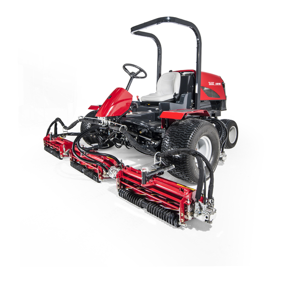
5-unit fairway mower
Hide thumbs
Also See for LM2400:
- Owner's operating manual (87 pages) ,
- Owner's operating manual (92 pages)
Table of Contents
Advertisement
Quick Links
Download this manual
See also:
Owner's Operation Manual
Advertisement
Chapters
Table of Contents

Related Manuals for Baroness LM2400


Summary of Contents for Baroness LM2400
- Page 1 5-Unit Fairway Mower Owner's operating manual "Required reading" Read this manual and the owner's manual for the engine before using the machine. Serial No.10001- Original Instructions Ver.1.0...
- Page 2 LM2400 Greeting Thank you for purchasing the Baroness machine. This manual explains proper handling, adjustment, and inspection of your machine. Prior to use, carefully read this manual to thoroughly understand the contents for safe and correct operation. We hope you will use the machine safely, and take advantage of its best performance.
- Page 3 The information described in this manual is subject to change for improvement without prior notice. When replacing parts, be sure to use genuine Baroness parts or parts designated by Kyoeisha. Note that the Baroness product warranty may not apply to defects caused by the use of parts from other companies.
- Page 4 LM2400 Introduction Purpose This machine is intended for cutting turf grass at golf courses. Do not use this machine in any way other than its intended purpose, and do not modify the machine. Operating this machine for other purposes and modifying it may be very dangerous and may cause damage to the machine.
-
Page 5: Table Of Contents
LM2400 Contents Safety............... Page 1-1 Safe Operating Practices........Page 1-2 Disposal............Page 2-1 Waste Disposal..........Page 2-2 Product Overview........... Page 3-1 Specifications..........Page 3-2 Names of Each Section........Page 3-3 Safety Signs and Instruction Signs....Page 3-4 Handling Instructions........Page 4-1 Inspection Before Use........Page 4-2 Tightening torques........ - Page 6 LM2400 Contents...
-
Page 7: Safety
LM2400 Safety Safe Operating Practices....... Page 1-2 Training...........Page 1-2 Preparation..........Page 1-2 Operation..........Page 1-3 Maintenance and storage....... Page 1-4 Page 1-1... -
Page 8: Safe Operating Practices
LM2400 Safety Failure to adequately follow these safety Lack of awareness of the effect of precautions may cause an accident resulting in ground conditions, especially slopes injury or death. Incorrect hitching and load distribution Never allow untrained personnel to service... - Page 9 LM2400 Safety Replace all fuel tanks and container caps Do not change the engine governor settings securely. or overspeed the engine. Operating the engine at excessive speed may increase the Check that operator’s presence controls, hazard of personal injury. safety switches and shields are attached and functioning properly.
- Page 10 LM2400 Safety Take care when loading or unloading the Never allow untrained personnel to service machine into a trailer or a truck. Load or machine. unload the machine in a flat and safe place. Allow the engine/muffler to cool before Before loading or unloading, set the parking checking/maintenance.
- Page 11 LM2400 Safety Charge batteries in an open well ventilated area, away from spark and flames. Unplug charger before connecting or disconnecting from battery. Wear protective clothing and use insulated tools. Keep all parts in good working condition and all hardware tightened. Replace all worn or damaged decals.
- Page 12 LM2400 Safety Page 1-6 Safe Operating Practices...
-
Page 13: Disposal
LM2400 Disposal Waste Disposal........Page 2-2 About the Waste disposal....... Page 2-2 Page 2-1... -
Page 14: Waste Disposal
LM2400 Disposal Waste Disposal About the Waste disposal Make sure that waste generated when servicing or repairing the machine is disposed of in accordance with local regulations. (e.g. waste oil, antifreeze batteries, rubber products, and wires etc.) Page 2-2 Waste Disposal... -
Page 15: Product Overview
LM2400 Product Overview Specifications......... Page 3-2 Specifications..........Page 3-2 Sound pressure level......Page 3-2 Sound power level........Page 3-2 Vibration level......... Page 3-3 Names of Each Section......Page 3-3 Serial Number Plate........Page 3-3 Specification Decal......... Page 3-4 Noise Emission Decal......Page 3-4 Year of Manufacture Decal..... -
Page 16: Specifications
LM2400 Product Overview Specifications Specifications Type LM2400 Total length 303 cm During operation 318 cm Dimensions Total width During transport 226 cm Total height (steering wheel) 135 cm Weight 1,300 kg Minimum turning radius 290 cm Type Kubota D1105-T (Diesel Turbo) -
Page 17: Names Of Each Section
LM2400 Product Overview Vibration level Brake pedal Seat Hand-arm vibration Hood This machine was confirmed to transmit a Muffler maximum vibration level of 2.90 m/s to hands Mower unit #3 and arms by measuring identical machines in Mower unit #5... -
Page 18: Specification Decal
If they are damaged, become dirty, or peel off, replace them with new ones. Part numbers for decals that need to be replaced are listed in the parts catalog. Order them from a Baroness dealer or Kyoeisha. wvzv36-001 Year of Manufacture Decal_001... -
Page 19: Safety Signs And Instruction Signs
LM2400 Product Overview Positions of Safety Decals and Instruction Decals 6iul4h-026 Positions of Safety Decals and Instruction Decals_004 6iul4h-027 Positions of Safety Decals and Instruction Decals_005 6iul4h-029 Positions of Safety Decals and Instruction Decals_001 6iul4h-030 Positions of Safety Decals and Instruction Decals_006... -
Page 20: Explanation About Safety Decals And Instruction Decals
LM2400 Product Overview Explanation about Safety Decals and Instruction Decals LM2400-0918Z0 Decal for operation 2 Warning Read the Owner's Operating Manual. Warning Apply the parking brake, stop the engine, remove the ignition key, and then leave the machine. Danger Danger Flying objects - All persons other than the operator must keep a safe distance from the machine. - Page 21 LM2400 Product Overview K4209000980 Hydraulic oil icon Read the Owner's Operating Manual. K 4 2 0 9 0 0 0 9 8 0 qigqnx-020 K4209001000 Diesel fuel icon Use No. 2 diesel fuel. (Low sulfur or ultra-low sulfur diesel fuel only)
- Page 22 LM2400 Product Overview K4205001540 Decal for caution to hot parts Warning High temperature - Do not touch. Otherwise, you will get K 4 2 0 5 0 0 1 5 4 0 burned. qigqnx-022 K4205001710 Decal, caution for ROPS Replace a damaged ROPS.
-
Page 23: Handling Instructions
LM2400 Handling Instructions Inspection Before Use......Page 4-2 Mower Unit Up/Down Lever....Page 4-26 Stop Valve..........Page 4-26 Reel Cutter (Cutting Cylinder) and Mower Lock Lever (Latch)....Page 4-27 Bed Knife (Bottom Blade)....... Page 4-2 Reel rotation switch......Page 4-27 Radiator Cover........Page 4-2 Slight Lift Switch........ -
Page 24: Inspection Before Use
LM2400 Handling Instructions Inspection Before Use Cleaning of Radiator Cover Be sure to perform an inspection before you start Important using the machine so that you will be able to take An unclean radiator cover may cause advantage of its optimum performance for a long overheating or damage to the engine. -
Page 25: Radiator
LM2400 Handling Instructions Carefully clean the front and back of the Radiator radiator with water or compressed air. Inspection of Radiator Coolant For details on handling the engine, please refer Inspection of Coolant to the separate Engine Operating Manual. For details on handling the engine, please refer Make sure that there is no damage to the to the separate Engine Operating Manual. - Page 26 LM2400 Handling Instructions If the coolant level in the reserve tank is Coolant Supply lower than the "LOW" mark, open the reserve tank cap and fill the tank with clean For details on handling the engine, please refer water up to the "FULL" mark.
-
Page 27: Oil Cooler
LM2400 Handling Instructions If the oil cooler has been contaminated with Warning dust, be sure to clean it. Do not touch the radiator or coolant during After operating the machine in a dusty environment, it is important to remove dust as engine operation or right after the engine has been turned off. - Page 28 LM2400 Handling Instructions Hydraulic Oil Supply Change of Hydraulic Oil Important Warning Do not mix different types of oil. When you change the hydraulic oil, be sure to drain it into a bowl and discard it in accordance with local laws and regulations.
-
Page 29: Air Cleaner
LM2400 Handling Instructions Open the tank cap, and then pour new oil Make sure that the air cleaner element is from the fill port until the oil level reaches not contaminated. the middle of the oil gauge on the hydraulic tank. -
Page 30: Battery
LM2400 Handling Instructions Replace the air cleaner cap, and then fix Battery it securely with the clips. Inspection of Battery For details on handling the battery, please refer to the separate Battery Instruction Manual. Danger Danger Keep fire away while inspecting or charging the battery. -
Page 31: Tire
LM2400 Handling Instructions Brake Supply of Battery Fluid For details on handling the battery, please refer Inspection of Brake to the separate Battery Instruction Manual. While traveling, depress the brake pedal firmly Danger Danger to make sure that the brake is applied effectively. -
Page 32: Belt
LM2400 Handling Instructions Position the machine so that the engine will Belt be level, then insert the oil gauge all the way to check the oil level. Inspection of Belt Caution The engine must be stopped when the belt is inspected. - Page 33 LM2400 Handling Instructions Change the engine oil more frequently if the Important engine oil is contaminated and, especially, if Be sure to use engine oil that is classified as you use the machine in dusty areas or operate the engine at high loads or in high...
-
Page 34: Fuel
LM2400 Handling Instructions Refuel up to the middle (marked in red) of the Fuel fuel gauge. The fuel tank capacity is approximately 38.0 Inspection of Fuel Quantity (38.0 L). With the machine on a level surface, observe the fuel gauge in the operation panel to check the fuel level. -
Page 35: Tightening Torques
LM2400 Handling Instructions Tightening torques Standard tightening torques Bolts and Nuts Important A number of bolts are used in each part of this machine. Be sure to re-tighten the bolts and nuts, because they may be loosened at the earlier stage of the use. -
Page 36: Tightening Torques
LM2400 Handling Instructions Heat-treated bolt Strength classification 8.8 Strength classification 10.9 Nominal diameter 10.9 tib3yb-002 tib3yb-003 kgf-cm lb-in kgf-cm lb-in 5 - 7 50.99 - 71.38 44.26 - 61.96 7 - 10 71.38 - 101.97 61.96 - 88.51 8 - 11 81.58 - 112.17... -
Page 37: Principal Tightening Torques
LM2400 Handling Instructions Principal tightening torques Tightening Torque by Model LM2400 Tighten the following bolts and nuts at the torque specified in the table. For thread locking adhesive, apply a middle strength thread locker (ThreeBond 1322 anaerobic adhesives). Tightening torque... -
Page 38: Adjustment Before Operating
LM2400 Handling Instructions Adjustment of Seat Adjustment Before Operating Use the seat adjustment lever to adjust the seat Adjustment of Steering Wheel back and forth. Adjust the position according to the operator's Warning body size. Since it is dangerous, do not adjust the The adjustment lever is located beneath the steering wheel while traveling. -
Page 39: Adjustment Of Cutting Height
LM2400 Handling Instructions Adjustment of Cutting Height Reel rotation/stop switching lever Rotate Roller (Roller Type) Stop Adjust the cutting height to fit your cutting work. With the adjustment nut, adjust the engagement You can adjust the front roller in four stages. -
Page 40: Procedure To Start / Stop Engine
LM2400 Handling Instructions To decrease cutting height: Procedure to Start / Stop Engine Loosen cutting height adjustment nut B, tighten cutting height adjustment nut A, Start / Stop of Engine then raise the rear roller. Procedure to Start Engine Use the cutting height gauge to... - Page 41 LM2400 Handling Instructions Fuel filter Important ON (Open) The thermo-start lamp turns off at the OFF (Close) specified time. However, the lamp turning off is not related to the glow plug generating Sit on the seat. heat. Depress the brake pedal and move the If the ignition key is left in the "GLOW"...
-
Page 42: Operation Of Each Section
LM2400 Handling Instructions Make sure that the charge lamp and oil The parking brake is applied. ・ pressure lamp turn off. The mower unit up/down lever is moved to ・ If they do not turn off, stop the engine and the neutral position. -
Page 43: Operation Decals
LM2400 Handling Instructions Operation Decals Stop valve 6n6oux-039 Instruction Decals_003 Decal, tilt steering 6n6oux-037 6n6oux-040 Operation Decals_001 Instruction Decals_004 Decal, mower unit up/down lever Decal, parking brake Decal, key switch Decal, reel rotation switch Decal, engine rotation Decal, slight lift switch... - Page 44 LM2400 Handling Instructions Decal, mower unit up/down lever It illustrates Up/Down of the mower unit. 1. Down 2. Up 6n6oux-041 STOP Decal, key switch It illustrates the position of the key switch. 1. OFF 2. ON 3. GLOW 4. START...
- Page 45 LM2400 Handling Instructions Decal, slight lift switch It illustrates ON/OFF of the slight lift function. 1. ON 2. OFF 6n6oux-043 Decal, light switch It illustrates ON/OFF of the light. 1. ON 2. OFF 6n6oux-044 Decal, stop valve It illustrates Stop/Open of the stop valve.
- Page 46 LM2400 Handling Instructions K4209001200 Decal, brake It illustrates the locking position for the parking brake. 6n6oux-006 Page 4-24 Operation of Each Section...
-
Page 47: Light Switch
LM2400 Handling Instructions Light Switch Throttle Lever The throttle lever is located in the operation Warning panel and enables you to adjust the engine rpm. The lights provide auxiliary lighting. Move the throttle lever toward "High" (the rabbit Do not travel or operate the machine at night icon) to increase the engine rpm, and toward "Low"... -
Page 48: Mower Unit Up/Down Lever
LM2400 Handling Instructions Note: Mower Unit Up/Down Lever Even if the reel rotation switch is set to the "Rotate" position, the reel cutter (cutting Caution cylinder) stops rotating when the mower unit up/ down lever is moved to the neutral position or Before raising or lowering the mower units, the mower units are raised. -
Page 49: Mower Lock Lever (Latch)
LM2400 Handling Instructions Mower Lock Lever (Latch) Reel rotation switch Caution Caution When the mower lock levers (latches) are The reel rotation switch must be set just engaged, do not operate the mower unit up/ before you start cutting work. In cases other down lever. -
Page 50: Slight Lift Switch
LM2400 Handling Instructions Slight Lift Switch Reel reverse switch ON (Rotate) Note: OFF (Stop) Depending on the specifications, this function may not be available. Reel Rotation/Stop Switching Lever Caution Caution When the mower lock levers (latches) are Before operating the reel rotation/stop... -
Page 51: Brake Pedal
LM2400 Handling Instructions The traveling pedal is located in the right foot The parking brake lock lever is located in the area. right foot area. When the forward side depressed, the machine When parking, depress the brake pedal and travels forward. When the backward side move the parking brake lock lever forward. -
Page 52: Underseat Cover
LM2400 Handling Instructions Lift up the hood. Remove two bolts located on the rear of the seat. i5jb7e-010 ljffir-001 Hood_002 When closing the hood, do the operation Underseat Cover_001 slowly. Bolt Insert the washer, then the pin. Bring the seat to the backmost position. -
Page 53: Instruments
LM2400 Handling Instructions Hour meter Instruments The hour meter is located at the back of the Instruments on the Operation Panel operation panel, and indicates the total operation time of the engine. Every six minutes of engine operation will increase the number at the first digit (black number on a white background) by one. -
Page 54: Fuel Gauge
LM2400 Handling Instructions Remove the load from the engine, idle the Pilot Lamps machine for five minutes, stop the engine, and then inspect the machine and perform any Charge Lamp necessary maintenance. The charge lamp is the left pilot lamp located in If the water temperature exceeds 105 degrees the operation panel. -
Page 55: Travel Of Machine
LM2400 Handling Instructions Thermo-start Lamp Overheat Warning Buzzer The thermo-start lamp is the middle pilot lamp If the water temperature inside the engine located in the operation panel. exceeds 105 degrees Celsius, a buzzer will When the ignition key is set to the "GLOW"... -
Page 56: Cutting Work
LM2400 Handling Instructions Slowly depress the traveling pedal. Unload valve The machine will start to travel. Remove the wheel stoppers. Towing the Machine Depress the brake pedal to release the parking brake. If the machine does not travel due to engine trouble, etc., you can move it in the following... -
Page 57: Transporting
LM2400 Handling Instructions Right before starting cutting work, set the anti-falling stop valve to the "Open" position. Release the mower lock levers (latches) for mower units #4 and #5. Set the slight lift switch to the "ON" position. Note: Depending on the specifications, this function may not be available. - Page 58 LM2400 Handling Instructions Page 4-36 Transporting...
-
Page 59: Maintenance
LM2400 Maintenance Maintenance Precautions...... Page 5-2 Maintenance Schedule......Page 5-2 Specified Values........Page 5-3 Main Consumable Parts......Page 5-4 Jacking up the machine......Page 5-4 About the Jacking up the machine..Page 5-4 Jack-up Points........Page 5-4 Greasing..........Page 5-5 About Greasing........Page 5-5... -
Page 60: Maintenance Precautions
Use tools appropriate for each maintenance operation. Caution For the safe and best performance of your machine, use Baroness genuine parts for replacement and accessories. Please note that our product warranty may be void if you use non-genuine parts for replacement or accessories. -
Page 61: Specified Values
LM2400 Maintenance Maintenance item Tightening the parts ○ Interlock system ○ Emergency switch Electrical wiring ○ Knife Steering chain Cutting height ○ Greasing, oiling ○ Tire ○ Rubber crawler V-belt Brake ○ Wire ○ △ Cover ○ Oil leakage ○... -
Page 62: Jacking Up The Machine
LM2400 Maintenance Main Consumable Parts Jack-up Points Part name Code Fan belt PF16241-9701-0 Oil element PF15241-3209-4 Air cleaner element PFT0270-1632-0 Fuel filter element PF1G313-4356-0 Hydraulic cartridge filter K3412000090 Suction filter K3413000020 Hydraulic oil (20 L can) K2913100200 Brake wire, left... -
Page 63: Greasing
LM2400 Maintenance Front right frame Other locations where the specified grease or lubricant is used are indicated in "Greasing Points". Add grease using the specified grease or lubricant. Greasing Points Grease nipples are installed in the following locations. Add grease every 50 hours of operation. - Page 64 LM2400 Maintenance Pedal shaft fulcrum Mower units #2 and #3 There are two locations. 8bq62b-176 8bq62b-173 Greasing Points_005 Mower unit fulcrum Greasing Points_002 Lift arm fulcrum There is one greasing point on each mower There is one greasing point on the lift arm unit.
- Page 65 LM2400 Maintenance Reel housing Rear left wheel There is one greasing point on the reel housing of each mower unit. 8bq62b-182 Greasing Points_011 8bq62b-179 Rear right wheel Greasing Points_008 Rear roller There is one greasing point each on the left and right of each mower unit.
-
Page 66: Back Lapping Of Reel Cutter (Cutting Cylinder)
During back lapping, do not use the reel rotation switch. Have the following items ready: Strips of newspaper, Abrasive [Back lapping powder 8bq62b-185 mixed with oil; or gel compound (Baroness genuine abrasive)], Brush. Greasing Points_014 Maintenance (Mower) Back Lapping of Reel Cutter (Cutting... - Page 67 LM2400 Maintenance Insert two or three strips of newspaper into Mower unit up/down lever the space between the reel cutter (cutting Neutral cylinder) and the bed knife (bottom blade) at an angle of 90 degrees. Then, rotate the reel Down...
-
Page 68: Maintenance (Main Body)
Set the reel reverse switch to the "OFF" Caution position. Refer to the Tightening Torque table. Note that the Baroness product warranty may not apply to defects caused by incorrect or overtorque tightening. Important Tighten the bolts in the tightening order (crosswise). -
Page 69: Adjustment Of Belt Tension
Remove the tire from the wheel mounting base. Caution 10 mm(0.39 in) Refer to the Tightening Torque Table. sdie3r-002 Note that the Baroness product warranty may Fan Belt_001 not apply to defects caused by incorrect or overtorque tightening, etc. Fan belt Blade... -
Page 70: Adjustment Of Brake
LM2400 Maintenance Depressing the brake pedal firmly, move the Lock nut parking brake lock lever forward with a foot. Adjustment bolt Make adjustments with the adjustment bolt Brake wire inside of the tire so that the latch of the Brake lever parking brake lock lever is positioned at arrow A (fourth notch from the bottom). -
Page 71: Long-Term Storage
LM2400 Maintenance Rotate the traction adjusting cam slowly Glow lamp timer until all wheels stop. Glow lamp Find the position where all wheels stop Fuel pump and lock the traction adjusting cam with Charge lamp, oil pressure lamp (engine oil the lock nut. - Page 72 LM2400 Maintenance Page 5-14 Long-Term Storage...
- Page 75 Head Office 1-26, Miyuki-cho, Toyokawa, Tel : (0533) 84 - 1390 Fax : (0533) 89 - 3623 Aichi-Pref. 442-8530 Japan. LM2400--UM--GBZ/14C-00-S.K C...