
Related Manuals for CAME FA40230


Summary of Contents for CAME FA40230
- Page 1 OPERATOR 11 9DW 02EN G a t e l i n e G a t e l i n e FOR SWING GATES Installation manual FA40230-FA40230CB English...
-
Page 2: Table Of Contents
Index General safety instructions Legend Description Packing list Intended use Operational limits Technical data Dimensions Main component parts System feasibility Preliminary checks Tools and equipment Types and thickness of cables Standard installation Application examples Installation Laying the corrugated tubing and fastening the brackets Installing the gearmotor and transmission arms Mounting the mechanical endstops (if no mechanical strike plates are included) Adjusting the limit switches... -
Page 3: General Safety Instructions
• This product is only intended to be used for the purpose it was designed. Any at any moment without warning. Always cut off the main electric power supply other use is therefore improper and dangerous. La CAME Cancelli Automatici before performing any cleaning or maintenance. -
Page 4: Legend
Intended use This operator is engineered and built by Came Cancelli Automatici S.p.A. in compliance with current safety regulations, to automate residential and apar- ment building siwng-gates. Any installation or use other than that indicated in this manual is forbidden. -
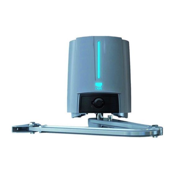
Page 5: Dimensions
Dimensions Gearmotor Fastening bracket Main component parts Cover FA40230 gearmotor FA40230CB gearmotor ZF4 electronic board Post-fastening bracket Transmission arm Drive arm Gate-fastening bracket Release hatch 10. Mechanical endstops. 11. UNI5931 M8x80 gearmotor fastening bolts 12. UNI7474 M8 nuts 13. limit-switch adjusting grub screws 14. -
Page 6: System Feasibility
System feasibility Installation must be carried by skilled, qualified technicians in accordance with current regulations. Preliminary checks Before beginning to install, do the following: Set up proper omnipolar cut-off device, with more than 3mm of distance between contacts, with sectioned power source; •... -
Page 7: Standard Installation
Standard installation FA40230CB Gate Operator FA40230 gearmotor Flashing light Antenna Key switch Photocells Small post for photocells End strike Junction pit-box Application examples... -
Page 8: Installation
Installation The following illustrations are just examples, in that the space for securing the operator and accessories depends on the installation zone. It is up to the installer to choose the most suited solution. Laying the corrugated tubing and fastening the brackets Set up the necessary corrugated tubing (Ø... - Page 9 Mark the fastening points for fastening the bracket to the post and for the fastening bracket to the gate. The centre distances of the bracket holes are shown in the paragraph about dimensions. Drill the fastening hole points, insert the plugs or use suitable inserts to hold the brackets. Note: the illustrations are indicative.
-
Page 10: Installing The Gearmotor And Transmission Arms
Installing the gearmotor and transmission arms Set up the required electrical cables threading them through the cable glands and blocking them to the gate post fastening U bracket. Insert the gearmotor into the bracket and fasten it with nuts and bolts ( Fit plug into the gearmotor shaft hole. -
Page 11: Mounting The Mechanical Endstops (If No Mechanical Strike Plates Are Included)
Mounting the mechanical endstops (if no mechanical strike plates are included) For the opening mechanical endstops . With the gearmotor released, completely open the leaf, manually. Mark the case near the centre of the arm. Centre of the arm Manually close the leaf. Insert the mechanical stop as shown. The mark on the case must match the groove on the stop. Mechanical endstop Fasten the stop using the bolt... - Page 12 For the closing mechanical endstops . With the gearmotor released, completely open the leaf, manually. Mark the case near the centre of the arm. Centre of the arm Manually open leaf. Insert the mechanical stop as shown. The mark on the case must match the groove on the stop. Mechanical endstop Fasten the stop using the bolt...
-
Page 13: Adjusting The Limit Switches
Adjusting the limit switches Adjusting the closing and opening endstop points of left-side gearmotors (internal view). With the gearmotor released and the gate leaf closed, adjust the closing limit-switch grub screw by turning it either clockwise or anti clockwise. Fasten the grub screw using the nut (see drawing). - Page 14 Adjusting the opening and closing endstop points of the right-side gearmotor (internal view). With the gearmotor released and the gate leaf closed, adjust the closing limit-switch grub screw by turning it either clockwise or anti clockwise. Fasten the grub screw using the nut (see drawing). In the same way, adjust the opening limit-switch by turning the grub screw of the other stop (see drawing).
-
Page 15: Manual Release Override And Blocking Of The Gearmotor
After making the electrical connections and necessary programming, fi t the cover onto the gearmotor and fasten it . Close the hatch Ž, block the gearmotor using the key and fi t the protective cap . Note: when fi tting the cover, be careful with the cable connecting the FA001 card to the electronic card. Manual release override and blocking of the gearmotor RELEASE - Remove the protective cap from the lock Œ... -
Page 16: Command And Control Electronics
Command and control electronics Description The control panel should be powered by 230 V AC, at 50/60 Hz frequency. the command devices and accessories are powered by 24 V. The accessories must not exceed 50 W overall. All connections are protected by quick fuses, see table. The functions on the entry and exit contacts, the time settings and user management, are all set and viewable on the display which is managed by the software. -
Page 17: Led Signal Light
- Red flashing LEDs 1, 2, - Red flashing LEDs 1 3 and 4, signal that the and 2, signal encoder normally closed (N.C.) malfunction, call for contacts are open (e.g. assistance. photocells, stop button). - The CAME logo stays lit always. -
Page 18: Electrical Connections
Electrical connections Power supplies Transformer Orange Purple Black Blue White Terminals for powering the 24V AC accessories Power supply at 230 Overall allowed power: 50 W 24V 12V 0 U V W X Y E L1T L2T CT V AC, Frequency 50 / 60 Hz 12 V - 15 W max. -
Page 19: Command Devices
Command devices Stop button (N.C. contact.). Gate stop button that excludes the automatic closing cycle, to resume movement press the command button or use another command device. N.B.: if contact is unused, select 0 (Deactivated) from the F 1 function. Opening device (N.O. -
Page 20: Gearmotor With Encoder
Gearmotor with encoder Default setting for electrical connections: FA40230CB FA40230 operator installed on the left and gearmotor installed on the right (internal view) with operator closing delay. FA40230CB FA40230 U V W X Y E + ENC1 - + ENC2 -... - Page 21 Photocells Photocells Photocells Confi gure contact CX or CY (N.C.), input for DELTA-S safety devices such as photocells, compliant with EN 12978 standards. See CX input functions (Function F2) or CY (Function 3) in: - C1 reopening when closing, while the gate is closing, opening the contact will invert movement until it is completely opened;...
-
Page 22: Photocells
Electrical connection for operating the photocell's safety test DIR / DELTA S DELTA 10 11 ES TS 1 2 3 3P 4 5 7 CX CY 10 11 ES TS 1 2 3 3P 4 5 7 CX CY With each opening and closing command, the card checks the effi ciency of the safety devices (i.e. photocells). Any anomalies in the working of the photocells is fl... -
Page 23: Programming
Programming Memorising data To register, edit or remove users or command the operator via radio transmitter, plug in the AF43S card. If using either the transponder of card reader, fit the R700 board or, alternatively, the R800 keypad selector board. Fit the memory roll to save and load registered users onto another board. -
Page 24: Menu Map
Setting the number of motors F 50 Saving date in the memory roll F 51 Reading memory roll data F 59 Enabling CAME logo feature Registering new users with associated command Cancelling one user Completely cancel users Motor test Calibrating travel... -
Page 25: Motor Test And Calibrarion Menu
Motor test and calibrarion menu Important! We suggest starting the programming by first doing the following: 1 Motor test; 2 Calibration of travel. Confirm with the ENTER button after choosing the value for each feature. A 2 (Motor test): test activation to check for proper rotation direction of the gearmotor (see the paragraph about motor test). -
Page 26: Features Menu
Features menu F 1 (Total Stop 1-2) - N.C. input: gate stop with consequent exclusion of possible automatic closing cycle; to restore movement act on the command device. Insert safety device on [1-C2]; if unused, select function "0. = 0 = Deactivated (default); 1 = activated >... - Page 27 F 7 (Command 2-7): setting the 2-7 contact to either the step (open-close) or sequential (open-stop-close-stop) modes. 0 = step-step (default); 1 = sequential. ENTER ENTER > > >...> F 8 (Command 2-3P): setting contact on 2-3P to pedestrian opening (total opening of the second leaf) or partial (partial opening of the second leaf depending on percentage setting between 10 and 80 of the travel, feature F 36).
- Page 28 F 18 (Light W-E): output on contact W-E for the light with the following feature: - movement warning flashing light, flashes while gate is opening and closing. - outdoor freely placeable light, to enhace lighting in the parking area, set as courtesy light which stays lit for a set time of 180 seconds or as a cycle light that stays on from the moment the leaf starts opening until it is completely closed (including automatic closing time) .
- Page 29 F 24 (Closing delay time): after a closing command or after automatic closing, the M2 gearmotor lead delays its start compared to gearmotor M1; the time is adjustable. the delay time can be deactivated or adjusted from 1" to 25". = 0 = Deactivated (default);...
- Page 30 F 38 (Closing slow down point): adjusts the motor's beginning slow down point before the closing endstop. the beginning deceleration point is calculated as a percentage of the leaf's complete travel (see par. illustration of slow down and end strike areas and points ) 10 = 10% of the travel;...
-
Page 31: Info Menu
F 59 (Enabling the CAME logo ): enables switching on or off of the CAME logo of after the gate is completely closed, it stays on for a time that can be adjusted to between10” and 180”. = 0 = Deactivated;... -
Page 32: Adding User With Associated Command
N.B.: during registering / cancelling new users operations, the fl ashing numbers viewed, are available and usable for any user needing to be registered ( maximum 25 users). Adding user with associated command Important! Before entering users, remove the memory roll card if present. User Associated com- mand... -
Page 33: Motor Test
Motor test Select A 2. Press ENTER to confirm. < > ENTER 1) Select 1 to activate the test. Press ENTER to confirm... < < < < > > > > ENTER - - - ... 3) ..."---" will appear on the screen, waiting for a command... -
Page 34: Calibrating Travel
Calibrating travel N.B.: before calibrating the travel, check that the manoeuvring area is free of any obstacles and check for the presence of any mechanical opening and closing strike-plates. Important! While calibrating, all safety devices will be deactivated until calibration is complete, except for the TOTAL STOP. Select A 3. -
Page 35: Error Messages
Error messages Er1: calibration of motor M1 interrupted; check proper connection and operation of motor M1. Er2: calibration of motor M2 interrupted; check proper connection and operation of motor M2. Er3: encoder out-of-order; call for assistance. Er4: services test error: check proper connections and functioning state of the safety devices. Er5: insuffi cient working time;... -
Page 36: Maintenance
COn its premises, Cancelli Automatici S.p.A. implements a certified Environmental Management System in compliance with the UNI EN ISO 14001 standard to ensure environmental protection. Please help us to safeguard the environment. At CAME we believe this to be one of the fundamentals of our market operations and development strate- gies. Just follow these short disposal instructions: DISPOSING OF THE PACKAGING The components of the packaging (i.e. -
Page 37: Ce Declaration
CE Declaration... - Page 38 (+34) 91 52 85 009 127273, Moscow Moscow (+34) 91 46 85 442 (+7) 495 739 00 69 (+7) 495 739 00 69 (ext. 226) CAME United Kingdom Ltd. CAME United Kingdom Ltd. GREAT BRITAIN PORTUGAL CAME Portugal CAME Portugal...